Hitachi ATW-RTU-07 Manual do usuário
- Categoria
- Aquecedores de ambiente
- Tipo
- Manual do usuário

–
–
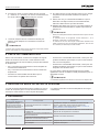
INSTALLATION
AND OPERATION
MANUAL
WIRELESS INTELLIGENT ROOM
THERMOSTAT
MODELS
ATW-RTU-07
INSTALLATION AND OPERATION MANUAL
MANUAL DE INSTALACIÓN Y FUNCIONAMIENTO
INSTALLATIONS- UND BETRIEBSHANDBUCH
MANUEL DʼINSTALLATION ET DE FONCTIONNEMENT
MANUALE DʼINSTALLAZIONE E DʼUSO
MANUAL DE INSTALAÇÃO E FUNCIONAMENTO
INSTALLATIONS- OG BETJENINGSVEJLEDNING
INSTALLATIE- EN BEDIENINGSHANDLEIDING
INSTALLATION- OCH DRIFTHANDBOK
ΕΓΧΕΙΡΙ∆ΙΟ ΕΓΚΑΤΑΣΤΑΣΗΣ ΚΑΙ ΛΕΙΤΟΥΡΓΙΑΣ
РЪКОВОДСТВОТО ЗА ИНСТАЛИРАНЕ И ЕКСПЛОАТАЦИЯ
EN
ES
DE
FR
IT
PT
DA
NL
SV
EL
BG
CS
ET
HU
LV
LT
PL
RO
RU
SK
UK
NÁVODEM K INSTALACI A OBSLUZE
PAIGALDUS- JA KASUTUSJUHEND
TELEPÍTÉSI ÉS ÜZEMELTETÉS ÚTMUTATÓJÁNAK
UZSTĀDĪŠANAS UN EKSPLUATĀCIJAS ROKASGRĀMATA
MONTAVIMO IR NAUDOJIMO VADOVĄ
INSTRUKCJA INSTALACJI I OBSŁUGI
MANUALUL DE INSTALARE ȘI UTILIZARE
РУКОВОДСТВО ПО УСТАНОВКЕ И ЭКСПЛУАТАЦИИ
NÁVOD NA PREVÁDZKU A INŠTALÁCIU
ПОСІБНИКА З МОНТАЖУ ТА ЕКСПЛУАТАЦІЇ
PMML0502 rev.1 - 01/2021

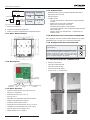
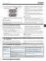
1 INSTALLATION INSTRUCTIONS
1.1 SAFETY SUMMARY
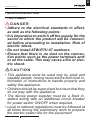
!DANGER
•Adhere to the electrical standards in effect,
aswellasthefollowingpoints:
•Itisimperativetoswitchoffthesupplyforthe
sectortowhichtheproductwillbeconnect-
edbeforeproceedingtoinstallation.Riskof
electricshock.
•DonotinstallATW-RTU-07outdoors.
•Ensurethatthereisnodustontheconnec-
tionpointssuchasthepowerterminalsand/
oronthecable.Thismaycauseareorelec-
tricshock.
!CAUTION
•Thisappliancemustbeusedonlybyadultand
capablepeople,havingreceivedthetechnicalin-
formationorinstructionstohandleproperlyand
safelythisappliance.
•Childrenshouldbesupervisedtoensurethatthey
donotplaywiththeappliance.
•The device power supplier must be a xed in-
stalled wiring with an additional circuit breaker
forpowerswitchON/OFFwhenrequired.
•Localornationalregulationsmustbefollowedat
alltimesduringthepreliminaryworktoprepare
theelectricpowerlinefortheequipment.
Installation instructions
PMML0502 rev.1 - 01/2021
1
EN

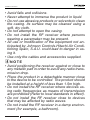
•Avoidfallsandcollisions.
•Neverattempttoimmersetheproductinliquid.
•Donotuseabrasiveproductsorsolventstoclean
thecasing.Itssurfacemaybecleanedusinga
soft,drycloth.
•Donotattempttoopenthecasing.
•Do not install the RF receiver where persons
wearingapacemakermaybepresent.
•Alluseormodicationoftheequipmentnotan-
ticipatedbyJohnsonControls-HitachiAirCondi-
tioningSpain,S.A.U.couldleadtodangerinus-
ingit.
•Useonlythecablesandaccessoriessupplied.
?NOTE
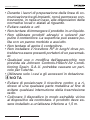
•Avoidpositioningthereceiveragainstorcloseto
anymetallicpartinordertoavoidanyradiotrans-
missiondrop.
•Placetheproductinadetachablemannerclose
tothedevicetobecontrolled.Theproductshould
beinstalledataheightoflessthan1.5mhigh.
•DonotinstalltheRFreceiverwheredevicesus-
ingradiofrequenciesasmeansoftransmission
areprohibited(Refertolocalstandardsineffect).
•Donot installthe RF receiverclose todevices
thatmaybeaffectedbyradiowaves.
•DonotinstalltheRFreceiverinadampenviron-
ment(forexample,abathroom).
Installation instructions
PMML0502 rev.1 - 01/2021
2

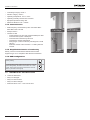
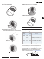
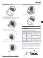
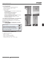
1.2 FACTORY SUPPLIED ACCESSORIES
Description Quantity
ATW-RTU-07 (Receiver + Thermostat) 1
Screw and plug 4
Installation and operation manual 1
Product che 1
1.3 INSTALLATION INFORMATION
As these products communicate using RF technology special
care must be taken during installation. The location of the RF
components as well as the building structure may inuence
performance of the RF system. To assure system reliability,
please review and apply the information given below.
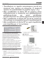
Within a typical residential building the two products should
communicate reliably within a 30m range.
It is important to take into consideration that walls and ceilings
will reduce the RF signal. The strength of the RF signal
reaching the RF Receiver depends on the number of walls and
ceilings separating it from the Room Thermostat, as well as the
building construction. Walls and ceilings reinforced with steel
or plasterboard walls lined with metal foil reduce the RF signal
signicantly more.
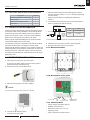
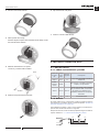
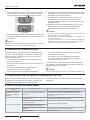
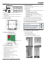
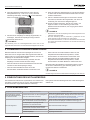
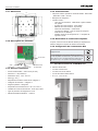
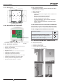
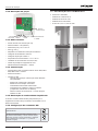
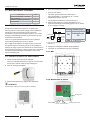
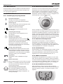
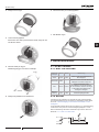
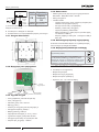
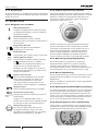
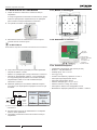
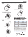
1.4 RF RECEIVER INSTALLATION
1 Disconnect the main power from the system.
To ensure your safety, always make sure main power is
switched off before accessing wiring.
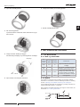
2 Remove the cover from the RF receiver.
3 Mount the wiring plate to the wall or wallbox.
?NOTE
Theplugsandmountingscrewsrequiredaresupplied.
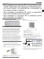
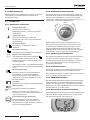
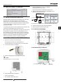
4 Connect the RF Receiver wiring.
• Connect the H-LINK cable.
• Place the cable through the orice identied by marker 3.
• Connect the power cable (L = Live ; N =Neutral) (Tightening
torque 0.50 Nm)
• Place the power cable in the cable guide identied by
marker 1.
5 The cables must be positioned in the box’s cable guides in
order to guarantee the pull-off strength.
1~ 230V 50Hz
LN
ATW-RTU-07
12
N
L
H-LINK
H-LINK
YUT
AKI
Te
rminal
Board
CB YUTAKI
Terminal
board
Item Notes
CB Circuit Breaker 5A
Cable 2 x 0.75 (1)
(1) Power cable type cannot be lighter than the specied in 60245 IEC 57.
6 Attach the cover of the RF receiver to the wiring plate.
7 Reconnect the mains power to the system.
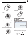
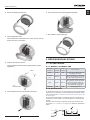
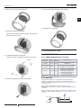
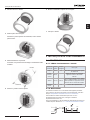
1.4.1 Dimensional data
98
98
80,79
91,77
88,57
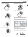
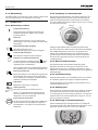
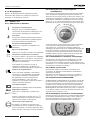
1.4.2 Description of the parts
Operation and
status LED
Power cord Not
used H-LINK
connection cable
Bind button
1.4.3 Technical data
• Supply voltage: 230V/50Hz (30mA)
• Wattage: 7W (maximum)
• Dimensions (mm): 123 x 115 x 37
• Weight (g): 214g
• Class 2 reinforced insulation device
Installation instructions
PMML0502 rev.1 - 01/2021
3
EN

• Overvoltage category: Class 2
• Pollution category: Class 2
• Operating Temperature: 0°C to + 60°C
• Operating Humidity: between 30% and 80%
• Equipment protection rating: IP21
• Maximum altitude for use: < 2000m
1.4.4 Communication
• Radio frequency and maximum power used: 868.0 MHz -
868.6 MHz / ERP <25 mW
• Receptor class 2
• YUTAKI H-LINK:
-Communication line: Non-polar, twisted shielded pair cable
-Communication system: Half-duplex
-Communication method: Asynchronous
-Transmission Speed: 9,600 bauds
-Wiring length: 1,000 m maximum (total length of H-LINK
I/O bus)
-Maximum number of RF receivers: 1 H-LINK system RF
receiver
1.4.5 Simplied declaration of conformity
Hereby, Johnson Controls-Hitachi declares that the radio
equipment type 2 is in compliance with directive 2014/53/EU.
1.4.6 DSW conguration
Factory setting
In case of applying high voltage to the terminal 1-2 of TB
(Transmitting wires), the fuse on the PCB is cut. In such
a case, rstly correct the wiring to TB and then turn ON
switch 1 (as shown in the gure)
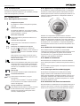
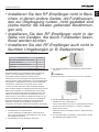
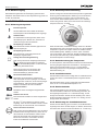
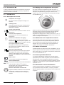
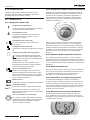
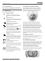
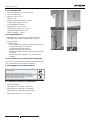
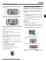
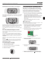
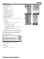
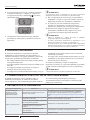
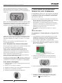
1.5 THERMOSTAT INSTALLATION
1 Locate the thermostat.
• Away from draughts
• Away from heat sources
• Away from direct sunlight
• Positioned about 1.2m – 1.5m from the oor
1.5 m
Do not place
in the sunlight Do not place
above a heat source
Avoid
air currents
Installation instructions
PMML0502 rev.1 - 01/2021
4

2 First remove the dial.
3 Unclip the mounting plate.
Press the top of the thermostat downwards, pull it loose and
tilt forwards.
4 Mount directly to the wall.
The plugs and mounting screws required are supplied.
Plugs
Screws
5 Remove the protective tab between the batteries.
6 Attach the thermostat to the mounting plate.
7 Replace the dial.
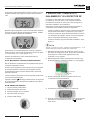
2 OPERATION INSTRUCTIONS
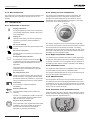
2.1 RF RECEIVER
2.1.1 Operation and status LED
RF
receiver
status
ON
Time
OFF
Time Description
Waiting 0.5 s 4 s There is no thermostat linked to the
RF receiver
Normal
operation Innite -There is at least 1 thermostat linked to
the receiver and there are no alarms.
Alarm 150
ms 150 ms
Communication fault between
RF receiver and YUTAKI unit, RF
communication lost with any of the
wireless thermostats or Faulty RF
receiver.
Binding 1 s 1 s Binding process
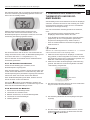
2.1.2 Reset
ATW-RTU-07 RF receiver and thermostat are already linked by default.
To verify if Reset has to be performed, check section “3Bindingthe
WirelessthermostatandRFReceiver”
To reset the stored data in order to create a new binding in ATW-RTU-07
press BIND button during 15 seconds.
After reset is being performed Status led shall blink according to
“Waiting” status dened in ”2.1.1OperationandstatusLED”.
0.5s 0.5s 0.5s
4s4s
Operation instructions
PMML0502 rev.1 - 01/2021
5
EN

2.1.3 RF transmission
The refresh time of the RF transmission (between wireless room
thermostat and main controller) is ranging from 30 sec to 2
minutes.
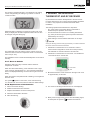
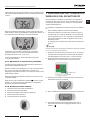
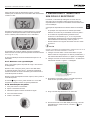
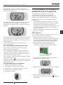
2.2 THERMOSTAT
2.2.1 Explanation of the icons
Setting temperature
The gure appearing on the screen corresponds
to the setting temperature, instead of the current
room temperature.
Heating on
Heating is demanding, and thus the heat pump
should be in operation, either intermittent or
continuous.
RF receiver binding
The thermostat is on binding process with the RF
receiver.
RF receiver connection
The thermostat is successfully connected to the
RF receiver.
Setting modication indication
In case that RF receiver connection symbol
is surrounded by this symbol means that setting
temperature has been updated from central
application.
This symbol is not displayed in case setting
temperature has been modied by turning the
thermostat wheel.
RF communication error
These icons ash to indicate that the signal from
the RF Receiver is not properly received. Check
that the RF Receiver is powered on, and consult
with your installer if this does not x the problem.
Low battery
It is necessary to replace the batteries
immediately.
F77
Defective thermostat
The thermostat is defective and needs to be
replaced.
The text F77 is displayed in addition to this icon
when communication with the YUTAKI unit has
failed for more than 180 seconds.
No power to the thermostat
If the thermostat screen appears blank after initial
installation, then check whether the protective
lm has been removed from the batteries.
Otherwise, try replacing the batteries.
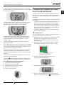
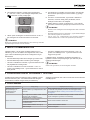
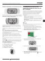
2.2.2 Setting of room temperature
The current room temperature is shown in the display. The
setting temperature can be changed by turning the dial to
the right to increase temperature, and to the left to reduce
temperature. The setting temperature changes in 0.5ºC steps,
one for each ‘click’ as the dial is turned.
I
n
c
r
e
a
s
e
C
L
I
C
K
D
e
c
r
e
a
s
e
The display changes to current room temperature again after
ve seconds have passed. Then the thermostat tries to maintain
the set temperature as accurately as possible. The setting
temperature can be checked by turning the dial one ‘click’ to the
left or right. It will ash up for a few seconds, before returning to
the display of room temperature again.
2.2.3 Night temperature reduction
It is recommended to set the thermostat to a lower temperature
at night and during absence periods, as it helps to save energy.
In general a reduction of 3°C is suggested, but this depends on
the heating system and the amount of insulation of the building.
2.2.4 Installation menu
The single zone thermostat has an installation menu that is used
to set the maximum and minimum temperature limits.
The maximum temperature that can be set on the thermostat is
35ºC and the minimum temperature is 5ºC.
2.2.5 ON/OFF Switch
The temperature dial is used to turn the system ON and OFF.
Turn the dial to the left until the displayed temperature is lower
or equal than 10 ºC in order to turn the system off. Turn the dial
to the right until the displayed temperature is more than 10 ºC in
order to turn the system ON again.
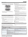
2.2.6 Activation of the installation menu
Rotate the setting ring fully to the left until the minimum value is
shown. When the value starts ashing, touch and hold on left or
right touch zones for approximately 10 s.
10s. 10s.
Operation instructions
PMML0502 rev.1 - 01/2021
6

The maximum temperature limit is now displayed. The setting
can be changed using the setting ring. There is no need to
conrm the value.
While this setting is ashing, touch the left or right touch zone
briey to display the minimum temperature limit. This can also
be changed using the setting ring.
The thermostat cannot be used to turn the system on and off
unless the limit for minimum temperature is set to a value lower
than 11ºC (ex: 5ºC).
The installation menu is closed automatically after 10 seconds of
inactivity.
2.2.7 Reset to default
Rotate the setting ring fully to the left until the minimum
temperature is shown.
When the value starts ashing, touch and hold on left or right
touch zones for approximately 10 s. The maximum temperature
limit is now displayed ashing, touch the left or right touch zone
briey.
When the minimum temperature limit is ashing, touch again the
left touch zone.
The symbol appears on the screen, touch and hold during
10 s the left touch zone and the device resets the default settings.
2.2.8 Replacement of the batteries
1 Pull to remove the dial ring.
2 Detach the thermostat from the base.
3 Replace the batteries as shown at the picture.
4 Attach the thermostat to the base.
5 Place the dial ring.
3 BINDING THE WIRELESS
THERMOSTAT AND RF RECEIVER
By default the thermostat is already linked to the RF receiver.
For these reason there is no need to perform binding procedure
in case it is only required one wireless thermostat at the
installation.
The binding operation described below is required if:
• Any of the system components (Room Thermostat or
RF Receiver) are replaced. Go to step 1.
• The RF Receiver has incorrect or no binding data stored
(e.g. when pre-bound system pack components have been
mismatched). Go to step 1.
• When adding a second wireless thermostat. Go to step 2.
?NOTE
Duringthebindingprocedurekeepapproximately1mdistancebetween
theRoomThermostatandtheRFReceiver.
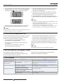
1 Hold button on RF Receiver for 15 seconds in order to
remove all the congurations. At the end of the procedure,
LED will ash 0.5 seconds ON and 4 seconds OFF.
2 Hold button on RF Receiver for 5 seconds. Led will ash for
1 seconds ON and 1 second OFF.
Press here
LED
3 Bind the thermostat. Touch and hold on the right touch zone
for approximately 10 seconds.
10s
4 The screen for binding the RF Receiver is now displayed.
5 Briey touch the right touch zone to send the binding signal,
at which point the symbol will ash several times.
Binding the Wireless thermostat and RF Receiver
PMML0502 rev.1 - 01/2021
7
EN

6 If binding has been successful the number indicates the
signal strength (1 = min to 5 = max). If binding fails,
appears on screen. Please try again.
Successful binding
Failed binding
7 The LED on the RF receiver is constantly ON to indicate that
the RF receiver is correctly linked with a thermostat.
?NOTE
Bindingcanbecancelledfromthebindingscreenbytouchingandholding
ontherighttouchzoneforapproximately10seconds.
8 If binding is unsuccessful, LED will ash. In this case,
change the location of the room thermostat and repeat the
procedure.
9 In case that there are 2 room thermostats and thermostat
1 is already linked, LED will be stay ON even if binding is
unsuccessful for thermostat 2.
10 Perform this step in case started from step 1. Repeat
the procedure from step 2 to 8 to bind the second room
thermostat.
?NOTE
• NotethattheRFreceiverclosesthebindingwindowafter2minutes
ofinactivity.
• TherstbindingissavedasThermostat1,andthesecondbinding(if
necessary)issavedasThermostat2.
• TheselectionofthezoneinwhichRoomthermostatwillbeusedis
doneatthe Roomthermostatmenu intheYUTAKILCDController
(PC-ARFH1E).
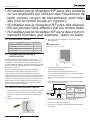
4 COMMUNICATION LOSS
In case of alarm the LED on the RF Receiver ashes 150 ms
ON and 150 ms OFF. The following list shows which types of
communication fails makes the RF receiver to enter into alarm
state.
• If there is a communications fault between the RF Receiver
and the Room Thermostat.
• If there is a fault in communications between the YUTAKI
and RF Receiver.
• If there is one Room Unit installed and communications is
lost with that zone.
• If there is more than one Room Unit installed, as in multi-
zone systems for example, and communications is lost with
one zone.
• If there is more than one Room Unit installed, as in multi-
zone systems for example, and communications is lost with
both zones.
In case of alarm, check wireless thermostats and check also
YUTAKI LCD Controller (PC-ARFH1E) to determine reason of
alarm.
?NOTE
LEDalsoshowsalarmincaseoffaultyRFreceiver.
5 FAIL-SAFE MODE SETUP
The fail-safe mode denes the system status if the RF
communication is lost (e.g. when the Room thermostat stops
communicating due to discharged batteries).
The system will continue to operate at the last communicated
setpoint.
6 TROUBLESHOOTING
Symptom (Fault Message) Possible Cause Remedy
The receiver box does not
react to setpoint changes on
the room thermostat.
The room thermostat and receiver box are
not bound.
Reset the receiver box by pressing and holding the push button
for 15 seconds. Then follow the binding / rebinding procedure as
described in section “3BindingtheWirelessthermostatandRF
Receiver”.
The LED shows alarm
There is no communication between
YUTAKI Unit and RF receiver.
Check H-LINK connection wire between YUTAKI Unit and RF
receiver and replace it if necessary.
The receiver box receives no RF messages
from the room thermostat. Re-locate the room thermostat.
RF signal is blocked due to wrong location
of the room thermostat.
Room thermostat batteries are exhausted. Replace batteries in the room thermostat.
Faulty receiver. Change the receiver.
Communication Loss
PMML0502 rev.1 - 01/2021
8

1 INSTRUCCIONES DE INSTALACIÓN
1.1 RESUMEN DE SEGURIDAD
!PELIGRO
•Respete la normativa eléctrica en vigor, así
comolassiguientesindicaciones:
•Antes de iniciar los trabajos de instalación
apague la alimentación eléctrica del sector
enelquevaaconectareldispositivo.Existe
riesgodedescargaeléctrica.
•NoinstaleelATW-RTU-07enelexterior.
•Asegúresedequenohayapolvoenlospun-
tosdeconexión,terminalesdealimentación
y/oenelcable.Podríaprovocarunadescar-
gaeléctricaofuego.
!PRECAUCIÓN
•Este dispositivo debe ser utilizado únicamente
porunadultooporunapersonaresponsableque
hayarecibidoformaciónoinstrucciones
•técnicasdecómomanipularlodeformaadecua-
daysegura.
•Vigilequelosniñosnojueguenconeldispositi-
vo.
•La fuente de alimentación del dispositivo debe
constardeuncableadojoinstaladoconundis-
yuntoradicionalparaelinterruptordealimentac-
ióndeMarcha/Parocuandoseanecesario.
Instrucciones de instalación
PMML0502 rev.1 - 01/2021
9
ES

•Durantelostrabajospreviosdepreparaciónde
lalíneadealimentacióneléctricaparaelequipo,
no está permitido contravenir, en ningún caso,
lasdisposicionesdelasnormativaslocalesoes-
tatalesalrespecto.
•Evitecaídasygolpes.
•Nosumerjaelproductoenlíquido.
•Noutiliceproductosabrasivosodisolventespara
limpiar la carcasa. Puede limpiar su supercie
conunpañosuaveyseco.
•Nointenteabrirlacarcasa.
•NoinstaleelreceptorRFenlugaresenlosque
puedahaberpersonasconmarcapasos.
•Cualquierusoomodicacióndelequiponopre-
vistaporJohnsonControls-HitachiAirCondition-
ingSpain,S.A.U.puedesuponerunpeligropara
elusuario.
•Utilicesololoscablesyaccesoriossuministra-
dos.
?NOTA
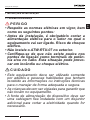
•No instale el receptor cerca de alguna pieza
metálica para evitar la caída de la transmisión
deradio.
•Coloqueeldispositivodeformaextraíblecerca
deldispositivoquesedebecontrolar.Eldisposi-
tivosedebeinstalaraunaalturamáximade1,5
m.
Instrucciones de instalación
PMML0502 rev.1 - 01/2021
10

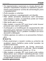
•NoinstaleelreceptorRFenlugaresdondeestén
prohibidoslosdispositivosqueutilizanfrecuen-
ciasderadiocomomediodetransmisión(con-
sultelanormativalocalvigente).
•NoinstaleelreceptorRFcercadedispositivos
quesepuedanverafectadosporlasondasde
radio.
•NoinstaleelreceptorRFenambienteshúmedos
(porejemplo,enunbaño).
1.2 ACCESORIOS SUMINISTRADOS DE
FÁBRICA
Descripción Cantidad
ATW-RTU-07 (receptor + termostato) 1
Tornillo y taco 4
Manual de instalación y funcionamiento 1
Ficha del producto 1
1.3 INFORMACIÓN PARA LA INSTALACIÓN
Como estos productos se comunican utilizando tecnología
RF debe prestar especial atención durante la instalación.
La ubicación de sus componentes, así como la estructura
del edicio, puede inuir en el rendimiento del sistema RF.
Para garantizar la abilidad del sistema, revise y aplique la
información que se ofrece a continuación.
Dentro de un edicio residencial típico, los dos productos deben
comunicarse de forma segura en una distancia de 30 m.
Es importante tener en cuenta que las paredes y los techos
reducirán la señal de RF. La intensidad de las señales que
llegan al receptor RF depende de la construcción del edicio
y de la cantidad de paredes y techos que lo separen del
termostato de ambiente. Las paredes y los techos reforzados
con acero o las paredes de pladur con perles metálicos
reducen considerablemente la señal RF.
1.4 INSTALACIÓN DEL RECEPTOR RF
1 Desconecte la alimentación principal del sistema.
Por su seguridad asegúrese, antes de acceder al cableado,
que la alimentación principal está siempre apagada.
2 Retire la cubierta del receptor RF.
3 Monte la placa de cableado en la pared o en la caja de
empotrar.
?NOTA
Lostacosytornillosestánincluidos.
4 Conecte los cables del receptor RF.
• Conecte el cable H-LINK.
• Pase el cable por el oricio identicado con un "3".
• Conecte el cable de alimentación (L = Fase; N = Neutro)
(par de apriete 0,50 Nm).
• Coloque el cable de alimentación en la guía identicada con
un "1".
5 Los cables se deben colocar en las guías de la caja para
garantizar su correcta sujeción.
Instrucciones de instalación
PMML0502 rev.1 - 01/2021
11
ES

1~ 230V 50Hz
LN
ATW-RTU-07
12
N
L
H-LINK
H-LINK
YUT
AKI
Te
rminal
Board
CB Cuadro de
terminales
YUTAKI
Elemento
Notas
CB
Disyuntor
5A
Cable 2 x 0,75
(1)
(1) El tipo de cable de alimentación no puede ser más ligero de lo que se
especica en 60245 IEC 57.
6 Coloque la cubierta del receptor RF.
7 Vuelva a conectar la alimentación principal del sistema.
1.4.1 Datos dimensionales
98
98
80,79
91,77
88,57
1.4.2 Descripción
LED de funcionamiento
y estado
Cable de
alimentación
No se
utiliza Cable de conexión
H-LINK
Botón de
ENLACE
1.4.3 Datos técnicos
• Tensión de alimentación: 230 V/50 Hz (30 mA)
• Potencia: 7 W (máximo)
• Dimensiones (mm): 123 x 115 x 37
• Peso (g): 214 g
• Dispositivo con aislamiento reforzado de clase 2
• Categoría de sobretensión: Clase 2
• Grado de contaminación: Clase 2
• Temperatura de funcionamiento: de 0 °C a +60 °C
• Humedad en funcionamiento: entre 30% y 80%
• Clase de protección del equipo: IP21
• Altitud máxima de uso: <2000 m
1.4.4 Comunicación
• Radiofrecuencia y potencia máxima utilizada: 868,0 MHz -
868,6 MHz / PRA <25 mW
• Receptor clase 2
• YUTAKI H-LINK:
-Línea de comunicación: cable de par trenzado blindado,
no polar.
-Sistema de comunicación: semidúplex
-Método de comunicación: asíncrono
-Velocidad de transmisión: 9.600 baudios
-Longitud del cableado: 1000 m máximo (longitud total del
bus H-LINK E/S)
-Número máximo de receptores RF: 1 receptor RF del
sistema H-LINK
1.4.5 Declaración de conformidad simplicada
Por la presente, Johnson Controls-Hitachi declara que el equipo
radioeléctrico tipo 2 cumple con la normativa 2014/53/UE.
1.4.6 Conguración del conmutador DIP
Ajuste de fábrica
En caso de aplicar alta tensión a los terminales 1-2 del
cuadro de terminales (cables de trasmisión), se corta el
fusible en la PCB. En ese caso, conecte en primer lugar
el cable al cuadro de terminales y a continuación coloque
el pin 1 en posición ON (como se muestra).
1.5 INSTALACIÓN DEL TERMOSTATO
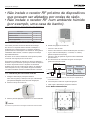
1 Coloque el termostato.
• Lejos de corrientes de aire
• Lejos de fuentes de calor
• Lejos de la luz solar directa
• A unos 1,2 m – 1,5 m del suelo
1,5 m
No lo exponga a la
luz del sol directa No lo coloque sobre
una fuente de calor
Evite las
corrientes de aire
Instrucciones de instalación
PMML0502 rev.1 - 01/2021
12

2 Primero retire el dial selector.
3 Abra la placa de montaje.
Presione la parte superior del termostato hacia abajo, tire de
él e inclínelo hacia delante.
4 Móntelo directamente en la pared.
Los tacos y tornillos están incluidos.
Tacos
Tornillos
5 Retire la cinta protectora de las pilas.
6 Fije el termostato a la placa.
7 Vuelva a colocar el dial selector.
2 INSTRUCCIONES DE USO
2.1 RECEPTOR RF
2.1.1 LED de funcionamiento y estado
Estado del
receptor
RF
Tiempo
encen-
dido
Tiempo
apagado Descripción
Espera 0,5 s 4 s No hay ningún termostato vinculado al
receptor RF.
Funcio-
namiento
normal
Innito -Hay al menos 1 termostato vinculado al
receptor y no hay alarmas.
Alarma 150 ms 150 ms
Fallo de comunicación entre el receptor
RF y la unidad YUTAKI, comunicación
RF perdida con cualquiera de los
termostatos inalámbrico o receptor RF
defectuoso.
Enlace 1 s 1 s Proceso de enlace
2.1.2 Reinicio
El receptor ATW-RTU-07 y el termostato ya están vinculados por defecto.
Para vericar si es necesario reiniciar, consulte el apartado “3Enlacedel
termostatoinalámbricoyelreceptorRF”.
Para restablecer los datos y crear un nuevo enlace en el ATW-RTU-07,
pulse el botón de ENLACE durante 15 segundos.
Después de reiniciar, el LED de estado parpadeará según el estado de
"Espera" denido en “2.1.1LEDdefuncionamientoyestado”.
0.5s 0.5s 0.5s
4s4s
Instrucciones de uso
PMML0502 rev.1 - 01/2021
13
ES

2.1.3 Transmisión RF
El tiempo de actualización de transmisión RF (entre el
termostato de ambiente inalámbrico y el controlador principal)
varía entre 30 segundos y 2 minutos.
2.2 TERMOSTATO
2.2.1 Descripción de los iconos
Temperatura de ajuste
En pantalla se muestra la temperatura ajustada,
no la real.
Calefacción encendida
Se demanda calefacción, por lo tanto la bomba
de calor debe estar en funcionamiento, ya sea de
forma intermitente o continua.
Enlace del receptor RF
El termostato está en proceso de enlace con el
receptor RF.
Conexión del receptor RF
El termostato está correctamente conectado al
receptor RF.
Indicación de modicación de ajustes
En caso de que el símbolo de conexión del
receptor RF esté rodeado por este símbolo, la
temperatura de ajuste se ha actualizado desde la
aplicación central.
Este símbolo no se muestra en caso de que la
temperatura se haya modicado mediante el dial
selector del termostato.
Error de comunicación RF
Estos iconos parpadean para indicar que la señal
del receptor RF no se ha recibido correctamente.
Compruebe que el receptor RF está encendido y
consulte con su instalador si esto no soluciona el
problema.
Batería baja
Es necesario cambiar las pilas inmediatamente.
F77
Termostato defectuoso
El termostato es defectuoso y hay que
reemplazarlo.
Junto al icono se muestra F77 cuando ha fallado
la comunicación con la unidad YUTAKI durante
más de 180 segundos.
No hay corriente en el termostato
Si la pantalla del termostato se muestra en blanco
tras la instalación inicial, compruebe si se ha
retirado la cinta protectora de las pilas. De lo
contrario, cambie las pilas.
2.2.2 Ajuste de la temperatura de la habitación
En la pantalla se muestra la temperatura real. La temperatura
de ajuste se puede modicar girando el dial selector hacia la
derecha para aumentar o hacia la izquierda para disminuir. Por
cada "clic" al girar el dial selector, la temperatura cambia en
intervalos de 0,5 °C.
A
u
m
e
n
t
a
C
L
I
C
D
i
s
m
i
n
u
y
e
Pasados cinco segundos la pantalla vuelve a mostrar la
temperatura real de la habitación. Después el termostato intenta
mantener la temperatura congurada con la mayor precisión
posible. La temperatura de ajuste se puede comprobar girando
el dial selector un "clic" a derecha o a izquierda. Parpadeará
unos segundos antes de volver a mostrar la temperatura de la
habitación.
2.2.3 Reducción de la temperatura nocturna
Para contribuir al ahorro energético es recomendable
congurar el termostato a temperaturas bajas durante la noche
y en ausencias prolongadas. En general, se recomienda
una reducción de 3 °C, pero esto depende del sistema de
calefacción y del aislamiento del edicio.
2.2.4 Menú de instalación
Este termostato de zona dispone de un menú de instalación
que se utiliza para ajustar los límites de temperatura máxima y
mínima.
En el termostato se puede ajustar una temperatura máxima de
35 °C y mínima de 5 °C.
2.2.5 Interruptor de Encendido/Apagado
El dial selector de temperatura se utiliza para encender y
apagar el sistema. Gire el dial selector hacia la izquierda
hasta que la temperatura mostrada sea inferior o igual a 10 °C
para apagar el sistema. Gire el dial selector hacia la derecha
hasta que la temperatura mostrada sea superior a 10 °C para
encender el sistema de nuevo.
2.2.6 Activación del menú de instalación
Gire el dial selector completamente a la izquierda hasta que se
muestre el valor mínimo. Cuando el valor parpadee, presione
durante unos 10 segundos la zona táctil izquierda o derecha.
10 s 10 s
Instrucciones de uso
PMML0502 rev.1 - 01/2021
14

Se muestra el límite de temperatura máxima. También se puede
modicar utilizando el dial selector. No hace falta conrmar el
valor.
Mientras el ajuste parpadea, toque la zona izquierda o derecha
para que se muestre el límite de temperatura mínima. También
se puede modicar utilizando el dial selector.
El termostato no se puede utilizar para encender y apagar el
sistema a menos que el límite de temperatura mínima se ajuste
a un valor inferior a 11 °C (por ejemplo, 5 °C).
El menú de instalación se cierra automáticamente tras
10 segundos de inactividad.
2.2.7 Restablecer valores predeterminados
Gire el dial selector completamente a la izquierda hasta que se
muestre la temperatura mínima.
Cuando el valor parpadee, presione durante unos 10 segundos
la zona táctil izquierda o derecha. Ahora parpadea el límite
de temperatura máxima. Presione brevemente la zona táctil
izquierda o derecha.
Cuando el límite de temperatura mínimo parpadee, presione de
nuevo la zona táctil izquierda.
Aparece el símbolo . Mantenga pulsada durante 10 segundos
la zona táctil izquierda y el dispositivo restablecerá los valores
predeterminados.
2.2.8 Cambio de baterías
1 Tire para extraer el dial selector.
2 Retire el termostato de la base.
3 Sustituya las pilas como se muestra.
4 Fije el termostato en la base.
5 Coloque el dial selector.
3 ENLACE DEL TERMOSTATO
INALÁMBRICO Y EL RECEPTOR RF
Por defecto, el termostato está correctamente conectado
al receptor RF. Por este motivo, no es necesario realizar el
procedimiento de enlace en caso de que solo se requiera un
termostato inalámbrico en la instalación.
Siempre que suceda alguna de las situaciones expuestas a
continuación, será necesario enlazar los dispositivos:
• Cuando se sustituya cualquiera de los componentes del siste-
ma (termostato de ambiente o receptor RF). Vaya al paso 1.
• Cuando el receptor RF tenga almacenados datos incorrectos
o no enlazados (por ejemplo, cuando se hayan emparejado
mal los componentes del sistema). Vaya al paso 1.
• Cuando se añada un segundo termostato inalámbrico. Vaya
al paso 2.
?NOTA
Durante el proceso de enlace, mantenga aproximadamente 1 m de
distanciaentreeltermostatodeambienteyelreceptorRF.
1 Mantenga pulsado el botón del receptor RF durante 15 seg.
para borrar la conguración actual. Durante el funcionamiento
de emergencia, el LED amarillo parpadeará 0,5 seg.
encendido y 4 seg. apagado.
2 Mantenga pulsado el botón del receptor RF durante 5 seg.
El LED parpadeará 1 segundo encendido y 1 seg. apagado.
Pulse aquí
LED
3 Enlace el termostato. Mantenga pulsada durante unos
10 segundos la zona táctil derecha.
10 s
4 Se muestra la pantalla para enlazar el receptor RF.
5 Toque la zona táctil derecha brevemente para enviar la señal
de enlace: en ese momento el símbolo parpadeará
varias veces.
Enlace del termostato inalámbrico y el receptor RF
PMML0502 rev.1 - 01/2021
15
ES

6 Si se ha enlazado con éxito, el número indica la fuerza de la
señal (1=mínimo, 5=máximo). Por el contrario, si el enlace
no se ha producido, se muestra . Vuelva a intentarlo.
Enlace exitoso
Enlace fallido
7 El LED del receptor RF está constantemente encendido para
indicar que el receptor RF está correctamente vinculado con
el termostato.
?NOTA
Elenlacesepuedecancelardesdelapantalladeenlacemanteniendo
pulsadaduranteunos10segundoslazonatáctilderecha.
8 Si el enlace no se ha realizado de forma satisfactoria, el LED
parpadeará. En tal caso, cambie la ubicación del termostato
de ambiente y repita el procedimiento.
9 En caso de que haya dos termostatos de ambiente y el
Termostato 1 ya esté vinculado, el LED se mantendrá
encendido incluso si el enlace con el Termostato 2 no se ha
realizado con éxito.
10 Realice este paso si ha empezado desde el paso 1. Para
enlazar el segundo termostato de ambiente, repita el
procedimiento desde el paso 2 hasta el paso 8.
?NOTA
• TengaencuentaqueelreceptorRFcierralaventanadeenlaceuna
veztranscurridos2minutossinactividad.
• ElprimerenlaceseguardacomoTermostato1,yelsegundo,silo
hay,comoTermostato2.
• La selección de la zona en la que se utilizará el termostato de
ambienteserealiza enelmenú deltermostatode ambiente,enel
controladorLCD(PC-ARFH1E)delaunidadYUTAKI.
4 PÉRDIDA DE COMUNICACIÓN
En caso de alarma, el LED del receptor RF parpadea 150 ms
encendido y 150 ms apagado. La siguiente lista muestra qué
tipos de errores de comunicación hacen que el receptor RF
entre en estado de alarma.
• Si hay un fallo de comunicación entre el receptor RF y el
termostato de ambiente.
• Si hay un fallo de comunicación entre la unidad YUTAKI y el
receptor RF.
• Si hay una unidad instalada en la habitación y la
comunicación con esa zona se pierde.
• Si hay más de una unidad instalada en la habitación,
como en los sistemas con varias zonas, y se pierde la
comunicación con una zona.
• Si hay más de una unidad instalada en la habitación,
como en los sistemas con varias zonas, y se pierde la
comunicación con las dos zonas.
En caso de alarma, compruebe los termostatos inalámbricos
y el controlador LCD (PC-ARFH1E) de la unidad YUTAKI para
determinar el motivo de la alarma.
?NOTA
ElLEDtambiénmuestraunaalarmaencasodereceptorRFdefectuoso.
5 CONFIGURACIÓN DEL MODO A PRUEBA DE FALLOS
El modo a prueba de fallos dene el estado del sistema en caso
de pérdida de comunicación RF (por ejemplo, si el termostato
de ambiente deja de comunicarse por pilas agotadas).
El sistema seguirá funcionando en el último punto de ajuste
comunicado.
6 RESOLUCIÓN DE PROBLEMAS
Síntoma (mensaje de
error) Posible causa Solución
El receptor no reacciona a
los cambios de punto de
ajuste del termostato de
ambiente.
El termostato de ambiente y el receptor no
están unidos.
Reinicie el receptor manteniendo pulsado el botón durante
15 segundos. A continuación, siga el procedimiento de enlace
descrito en el apartado “3Enlacedeltermostatoinalámbricoyel
receptorRF”.
El LED muestra una alarma.
No hay comunicación entre la unidad YUTAKI
y el receptor RF.
Compruebe el cable de conexión H-LINK entre la unidad YUTAKI y
el receptor RF y sustitúyalo si es necesario.
El receptor no recibe mensajes RF del
termostato de ambiente. Reubique el termostato de ambiente.
La señal RF está bloqueada por una mala
ubicación del termostato de ambiente.
Las pilas del termostato de ambiente están
agotadas. Sustituya las pilas del termostato de ambiente.
Receptor defectuoso. Sustituya el receptor.
Pérdida de comunicación
PMML0502 rev.1 - 01/2021
16

1 INSTALLATIONSANWEISUNGEN
1.1 SICHERHEITSÜBERSICHT
!GEFAHR
•HaltenSiesichandievorgegebenenStrombes-
timmungensowieandiefolgendePunkte:
•VorderInstallationdesProduktsmussunbed-
ingtdieStromversorgungfürdenentsprech-
enden Sektor abgeschaltet werden. Gefahr
einesStromschlags.
•InstallierenSieATW-RTU-07nichtimFreien.
•ÜberprüfenSie,dasskeinStaubandenAn-
schlüssenwiederStromanschlussoderden
Kabeln ist. Dadurch könnten Stromschläge
oderBrandverursachtwerden.
!VORSICHT
•DiesesGerätdarfnurvonErwachsenenundbe-
fähigtenPersonenbetriebenwerden,diezuvor
technische Informationen oder Instruktionen zu
dessensachgemäßenundsicherenHandhabung
erhaltenhaben.
•Achten Sie darauf, dass Kinder nicht mit dem
Gerätspielen.
•Die Gerätestromversorgung muss eine fest in-
stallierte Verkabelung mit einem zusätzlichen
Trennschalter für den Stromschalter EIN/AUS
sein,wenndieserforderlichist.
Installationsanweisungen
PMML0502 rev.1 - 01/2021
17
DE

•BeidenArbeitenzurVorbereitungderStromver-
sorgungsleitungderAnlagedarfinkeinemFall
gegen die diesbezüglichen regionalen und na-
tionalenRichtlinienverstoßenwerden.
•StürzeundKollisionenvermeiden.
•DasProduktnieinFlüssigkeitentauchen.
•KeineaggressivenProdukteoderLösungsmittel
zurReinigungdesGehäusesbenutzen.DieOber-
äche sollte mit einem trockenen und weichen
Tuchgereinigtwerden.
•Nichtversuchen,dasGehäusezuöffnen.
•Installieren Sie den RF-Empfänger nicht in der
NähevonPersonenmitHerzschrittmachern.
•JeglicherGebrauchoderjeglicheVeränderungen
desGeräts,dienichtvonJohnsonControls-Hi-
tachiAirConditioningSpain,S.A.U.vorhergese-
hen sind, können beim Gebrauch eine Gefahr
darstellen.
•VerwendenSienurdieKabelunddasZubehör,
dasmitgeliefertwurde.
?HINWEIS
•StellenSiedenEmpfängernichtinderNähevon
metallischen Teilen auf, um Störungen in der
Funkübertragungzuvermeiden.
•StellenSiedasProduktsoauf,dassessichher-
ausnehmen lässt und sich in der Nähe des zu
steuerndenGerätsbendet.DasProduktsolltein
einerHöheniedrigerals1,5minstalliertwerden.
Installationsanweisungen
PMML0502 rev.1 - 01/2021
18

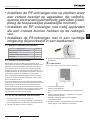
•InstallierenSiedenRF-EmpfängernichtinBere-
ichen,indenenandereGeräte,dieFunkfrequen-
zenzurÜbertragungnutzen,nichtgestattetsind
(siehehierfürdielokalengeltendenBestimmun-
genein).
•Installieren Sie den RF-Empfänger nicht in der
NähevonGeräten,diedurchFunkwellenbeein-
usstwerdenkönnen.
•InstallierenSiedenRF-Empfängerauchnichtin
feuchtenUmgebungen(z.B.Badezimmer).
1.2 MITGELIEFERTES ZUBEHÖR
Beschreibung Menge
ATW-RTU-07 (Empfänger + Thermostat) 1
Schraube und Dübel 4
Installations- und Betriebshandbuch 1
Datenblatt 1
1.3 INSTALLATIONS-INFORMATION
Da diese Produkte zur Kommunikation die RF-Technologie
nutzen, muss die Installation mit besonderer Sorgfalt
durchgeführt werden. Sowohl der Standort der RF-
Komponenten als auch die Bauart des Gebäudes können die
Leistung des RF-Systems beeinussen. Um die Zuverlässigkeit
des Systems zu gewährleisten, lesen Sie die nachstehenden
Informationen sorgsam durch und halten Sie sich daran.
In einem normalen Wohnhaus sollten die beiden Geräte in
einem 30-Meter-Radius zuverlässig miteinander kommunizieren.
Bei der Kommunikation ist zu berücksichtigen, dass Wände
und Decken das die Stärke des RF-Signals schwächen. Die
Stärke, mit der das RF-Signal den RF-Empfänger erreicht,
hängt sowohl von der Anzahl der Wände und Decken ab, die
ihn vom Raumthermostat trennen, als auch von der Bauform
des Gebäudes. Wände und Decken, die durch Stahl oder
Gipskarton verstärkt und mit Metallfolie überzogen sind,
verursachen eine deutlich stärkere Abschwächung des Signals.
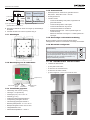
1.4 RF-EMPFÄNGERINSTALLATION
1 Den Netzstrom vom System trennen.
Um Ihre Sicherheit zu gewährleisten, stellen Sie immer
sicher, dass der Netzstrom abgeschaltet ist, bevor Sie auf
die Verkabelung zugreifen.
2 Die Abdeckung vom RF-Empfänger entfernen.
3 Die Verdrahtungsplatte an die Wand oder an die Wandbox
montieren.
?HINWEIS
DieerforderlichenDübelundMontageschraubenwerdenmitgeliefert.
4 Das RF-Empfängerkabel anschließen.
• Schließen Sie das H-LINK-Kabel an.
• Führen Sie das Kabel durch die mit 3 gekennzeichnete Öffnung.
• Schließen Sie das Stromkabel an (L = Phase; N =Nullleiter)
(Drehmoment 0,50 Nm)
• Platzieren Sie das Stromkabel in die mit 1 gekennzeichnete
Kabelführung.
5 Um die Kabel richtig zu befestigen, müssen diese in die Box
der Kabelführungen platziert werden.
Installationsanweisungen
PMML0502 rev.1 - 01/2021
19
DE
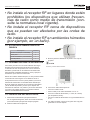
A página está carregando...
A página está carregando...
A página está carregando...
A página está carregando...
A página está carregando...
A página está carregando...
A página está carregando...
A página está carregando...
A página está carregando...
A página está carregando...
A página está carregando...
A página está carregando...
A página está carregando...
A página está carregando...
A página está carregando...
A página está carregando...
A página está carregando...
A página está carregando...
A página está carregando...
A página está carregando...
A página está carregando...
A página está carregando...
A página está carregando...
A página está carregando...
A página está carregando...
A página está carregando...
A página está carregando...
A página está carregando...
A página está carregando...
A página está carregando...
A página está carregando...
A página está carregando...
A página está carregando...
A página está carregando...
A página está carregando...
A página está carregando...
A página está carregando...
A página está carregando...
A página está carregando...
A página está carregando...
A página está carregando...
A página está carregando...
A página está carregando...
A página está carregando...
A página está carregando...
A página está carregando...
A página está carregando...
A página está carregando...
A página está carregando...
A página está carregando...
A página está carregando...
A página está carregando...
A página está carregando...
A página está carregando...
A página está carregando...
A página está carregando...
A página está carregando...
A página está carregando...
A página está carregando...
A página está carregando...
A página está carregando...
A página está carregando...
A página está carregando...
A página está carregando...
A página está carregando...
A página está carregando...
A página está carregando...
A página está carregando...
A página está carregando...
A página está carregando...
A página está carregando...
-
 1
1
-
 2
2
-
 3
3
-
 4
4
-
 5
5
-
 6
6
-
 7
7
-
 8
8
-
 9
9
-
 10
10
-
 11
11
-
 12
12
-
 13
13
-
 14
14
-
 15
15
-
 16
16
-
 17
17
-
 18
18
-
 19
19
-
 20
20
-
 21
21
-
 22
22
-
 23
23
-
 24
24
-
 25
25
-
 26
26
-
 27
27
-
 28
28
-
 29
29
-
 30
30
-
 31
31
-
 32
32
-
 33
33
-
 34
34
-
 35
35
-
 36
36
-
 37
37
-
 38
38
-
 39
39
-
 40
40
-
 41
41
-
 42
42
-
 43
43
-
 44
44
-
 45
45
-
 46
46
-
 47
47
-
 48
48
-
 49
49
-
 50
50
-
 51
51
-
 52
52
-
 53
53
-
 54
54
-
 55
55
-
 56
56
-
 57
57
-
 58
58
-
 59
59
-
 60
60
-
 61
61
-
 62
62
-
 63
63
-
 64
64
-
 65
65
-
 66
66
-
 67
67
-
 68
68
-
 69
69
-
 70
70
-
 71
71
-
 72
72
-
 73
73
-
 74
74
-
 75
75
-
 76
76
-
 77
77
-
 78
78
-
 79
79
-
 80
80
-
 81
81
-
 82
82
-
 83
83
-
 84
84
-
 85
85
-
 86
86
-
 87
87
-
 88
88
-
 89
89
-
 90
90
-
 91
91


Hitachi ATW-RTU-07 Manual do usuário
- Categoria
- Aquecedores de ambiente
- Tipo
- Manual do usuário
em outras línguas
- español: Hitachi ATW-RTU-07 Manual de usuario
- français: Hitachi ATW-RTU-07 Manuel utilisateur
- italiano: Hitachi ATW-RTU-07 Manuale utente
- Deutsch: Hitachi ATW-RTU-07 Benutzerhandbuch
- dansk: Hitachi ATW-RTU-07 Brugermanual
Artigos relacionados
-
Hitachi ATW-RTU-05 Instruções de operação
-
-
-
Hitachi RWH-(4.0-6.0)(V)NNF(W)E Yutaki S80 Series Indoor Units Manual do usuário
-
-
-
-
-