Airzone KNX TP-1 Manual do usuário
- Categoria
- Condicionadores de ar de sistema split
- Tipo
- Manual do usuário


ES
EN
FR
IT
PT
DE
ÍNDICE
Precauciones y política medioambiental ..........................................................................................................................................................................3
Precauciones ............................................................................................................................................................................................................................3
Política medioambiental .....................................................................................................................................................................................................3
Puerto de comunicaciones RS-485 ......................................................................................................................................................................................4
Conexión ...................................................................................................................................................................................................................................4
Protocolo Modbus ......................................................................................................................................................................................................................5
Configuración dirección esclavo en el dispositivo Aidoo control Wi-Fi/Pro ..................................................................................................5
Códigos de función Modbus ...................................................................................................................................................................................................6
Comandos Modbus ....................................................................................................................................................................................................................7
Comandos de escritura ........................................................................................................................................................................................................7
Escritura de un solo registro ........................................................................................................................................................................................7
Escritura de múltiples registros ..................................................................................................................................................................................7
Comandos de lectura ...........................................................................................................................................................................................................8
Pregunta ..............................................................................................................................................................................................................................8
Respuesta ............................................................................................................................................................................................................................8
Registros .........................................................................................................................................................................................................................................9
Registros de dispositivo esclavo ......................................................................................................................................................................................9

3
ES
EN
FR
IT
PT
DE
PRECAUCIONES Y POLÍTICA MEDIOAMBIENTAL
PRECAUCIONES
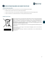
Por su seguridad y la de los dispositivos, respete las siguientes instrucciones:
• No manipule el sistema con las manos mojadas ni húmedas.
• Realice todas las conexiones o desconexiones con el sistema de climatización sin alimentar.
• Tenga precaución de no realizar ningún cortocircuito en ninguna conexión del sistema.
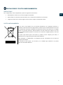
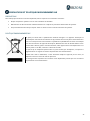
POLÍTICA MEDIOAMBIENTAL
No tire nunca este equipo con los desechos domésticos. Los productos eléctricos y
electrónicos contienen sustancias que pueden ser dañinas para el medioambiente si no se les
da el tratamiento adecuado. El símbolo del contenedor de basura tachado indica la recogida
selectiva de aparatos eléctricos, diferenciándose del resto de basuras urbanas. Para una
correcta gestión ambiental, deberá ser llevado a los centros de recogida previstos, al final de
su vida útil.
Las pieza
s que forman parte del mismo se pueden reciclar. Respete, por tanto, la
reglamentación en vigor sobre protección medioambiental.
Debe entregarlo a su distribuidor si lo reemplaza por otro, o depositarlo en un centro de
recogida especializado.
Los infractores están sujetos a las sanciones y a las medidas que establece la Ley sobre
protección del medio ambiente.

4
ES
EN
FR
IT
PT
DE
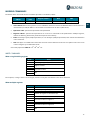
PUERTO DE COMUNICACIONES RS-485
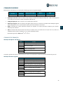
El RS-485, o también conocido como EIA-485, es un estándar de comunicaciones en bus.
Bus de integración
Velocidad del puerto de comunicación
19200 bps
Modo de comunicación
Half duplex
Longitud de la trama
8 bits
Bist de parada
1 bit
Control de flujo
Ninguno
Paridad
Par
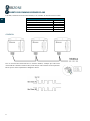
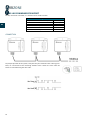
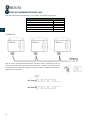
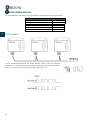
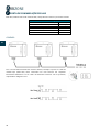
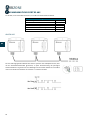
CONEXIÓN
Para el correcto funcionamiento de los sistemas Airzone, verifique que sólo están
conectados los cables de comunicación (verde-azul) en cada terminal en los respectivos
buses. Fije los cables respetando el código de colores.

5
ES
EN
FR
IT
PT
DE
PROTOCOLO MODBUS
Modbus es un protocolo de comunicaciones basado en la arquitectura maestro/esclavo, el cual organiza la información a
nivel físico en formatos o grupos lógicos de información.
Cada dispositivo de la red Modbus posee una dirección única. El dispositivo maestro envía un comando en una trama, en la
cual está contenida la dirección del dispositivo o dispositivos destinatarios (esclavos). Todos los dispositivos reciben la trama,
pero sólo el destinatario interpreta y ejecuta el comando, devolviendo un mensaje de confirmación o un mensaje de error.
Nota: Existe la posibilidad de enviar información a multitud de dispositivos de manera simultánea a través de una trama
denominada Broadcast.
Cada uno de los mensajes enviados incluye información redundante que asegura su integridad en la recepción. Si pasado cierto
tiempo el maestro no recibe confirmación, entiende que se ha producido un error y termina la comunicación.
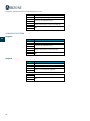
El modo de transmisión utilizado es MODBUS-RTU. Cada byte de datos se representa mediante dos caracteres de 4 bits en
hexadecimal. El formato de la trama es la siguiente:
Start
0
1
2
3
4
5
6
7
Paridad
Stop
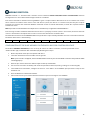
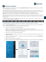
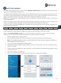
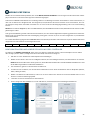
CONFIGURACIÓN DIRECCIÓN ESCLAVO EN EL DISPOSITIVO AIDOO CONTROL WI-FI/PRO
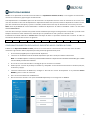
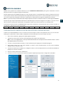
El Aidoo es un dispositivo Modbus esclavo, por ello es necesario indicar la dirección de este. Para ello, asocie su Aidoo
mediante la app “Airzone Aidoo” (disponible para iOS y Android) siguiendo estos pasos:
1. En el menú desplegable pulse la opción Añadir dispositivo.
2. Seleccione la unidad del listado de unidades disponibles que desea añadir para obtener información.
Nota: Si su unidad no aparece confirme que la función Bluetooth de su dispositivo iOS o Android está activado y que el Aidoo
está encendido y funciona correctamente.
3. En caso de ser necesario introduzca el código pin que se encuentra en el Aidoo.
4. Puede ejecutar acciones de prueba para identificar y comprobar el correcto funcionamiento de su unidad (calor, frío,
ventilación y apagar).
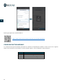
5. Seleccione Información del Webserver, configure la dirección de esclavo del dispositivo en el parámetro Puerto
Modbus y pulse el icono de validación.
6. Cierre la ventana Información del Webserver.
7. No será necesario continuar con el proceso Añadir dispositivo para su integración vía Modbus.

6
ES
EN
FR
IT
PT
DE
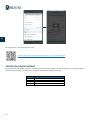
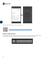
Puede descargar la aplicación “Airzone Aidoo” aquí:
https://www.airzonecontrol.com/ib/es/soluciones_de_control/aidoo/Wi-Fi
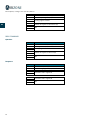
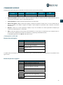
CÓDIGOS DE FUNCIÓN MODBUS
Los comandos básicos Modbus permiten controlar un dispositivo para modificar el valor de alguno de sus registros (espacio en
memoria) o bien solicitar el contenido de dichos registros; según los diferentes códigos de función:
Código
Función
03
Lectura de registros de salida o internos
04
Lectura de registros de entrada
06
Escritura de un solo registro
16
Escritura de múltiples registros

7
ES
EN
FR
IT
PT
DE
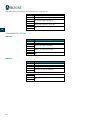
COMANDOS MODBUS
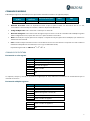
El formato que siguen los comandos para las operaciones de lectura/escritura es el siguiente (8 byte):
Dirección de
esclavo
Código de
operación
Dirección de registro Datos CRC
1 byte
1 byte
2 bytes
1…2·N bytes
2 bytes
• Dirección de esclavo. Define el dispositivo esclavo al que se quiere acceder. Las direcciones son de 1 a 247,
reservándose la dirección 0 para transmitir a todos los dispositivos (Broadcast).
• Código de Operación. Indica la función a realizar por el comando.
• Dirección de Registro. Indica la dirección del registro al que se desea acceder. En comandos sobre múltiples registros
define el Registro de Inicio, a partir del cual se va a operar de forma consecutiva.
• Datos. Formado por 2 bytes (operaciones simples) o conjunto de 2 bytes (operaciones múltiples) que contienen la
información del comando.
• CRC. Se añaden 2 bytes al final de la trama a fin de detectar errores en la transmisión o recepción. Para ello se utiliza el
método de Comprobación de redundancia cíclica (Cyclic Redundant Code).
El polinomio generador es: CRC-16 = x16 + x15 + x2 + 1.
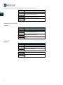
COMANDOS DE ESCRITURA
Escritura de un solo registro
Byte
Campo
0
Dirección de esclavo (1-247) (0: Broadcast)
1
Escritura de un solo registro (6)
2
Dirección de registro
3
4
Datos a escribir
5
6
CRC
7
La respuesta, siempre y cuando no se produzca ningún tipo de error, debe tener exactamente el mismo formato que el
comando de escritura.
Escritura de múltiples registros
Byte
Campo
0
Dirección de esclavo (1-247) (0: Broadcast)
1
Escritura de múltiples registros (16)
2
Dirección de registro de inicio
3
Número de registros a escribir (N)
4
5
Número de bytes totales de escritura (2·N)
6
Datos a escribir en registro 1
7
…
5+2·N
Datos a escribir en registro N
6+2·N
7+2·N
CRC
8+2·N

8
ES
EN
FR
IT
PT
DE
La respuesta, siempre y cuando no se produzca ningún tipo de error, será:
Byte
Campo
0
Dirección de esclavo (1-247) (0: Broadcast)
1
Escritura de múltiples registros (16)
2
Dirección de registro de inicio
3
4
Número de registros a escribir (N)
5
6
CRC
7
COMANDOS DE LECTURA
Pregunta
Byte
Campo
0
Dirección de esclavo (1-247) (0: Broadcast)
1
Lectura de registros (3/4)
2
Dirección de registro de inicio
3
4
Número de registros a leer (N)
5
6
CRC
7
Respuesta
Byte
Campo
0
Dirección de esclavo (1-247) (0: Broadcast)
1
Lectura de registros (3/4)
2
Número de bytes respuesta (2·N)
3
Datos a leer en registro 0
4
…
3+2·N
Datos a leer en registro N
4+2·N
5+2·N
CRC
6+2·N

9
ES
EN
FR
IT
PT
DE
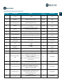
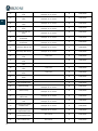
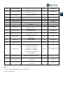
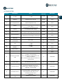
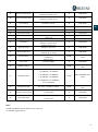
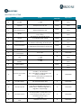
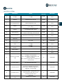
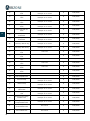
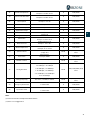
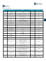
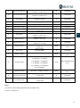
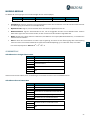
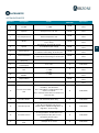
REGISTROS
REGISTROS DE DISPOSITIVO ESCLAVO
Registers Description Values
Read (R)
Write (W) Operations
0 On/Off
0 OFF
1 ON R & W
0x03, 0x04, 0x06, 0x10,
0x16
1 Setpoint* Setpoint x 10
Example: 22.5 ºC 225 R & W
0x03, 0x04, 0x06, 0x10,
0x16
2 Local temperature** Room Temperature x10 R & W
0x03, 0x04, 0x06, 0x10,
0x16
3 Modes 1 Auto; 2 Cooling; 3 Heating; 4
Fan; 5 Dry R & W
0x03, 0x04, 0x06, 0x10,
0x16
4 Speeds
0 Auto; 25 Silent; 50 Low;
75 Medium; 100 High R & W 0x03, 0x04, 0x06, 0x10,
0x16
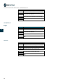
5 Louver Vertical
0
Stop; 8
Auto pos;
9 Vertical auto Swing; 10 Swril pos R & W 0x03, 0x04, 0x06, 0x10,
0x16
6 Louver Horizontal
0 Stop; 8 Auto pos;
9 Horizontal auto Swing; 10 Swril pos R & W 0x03, 0x04, 0x06, 0x10,
0x16
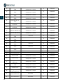
7
Unit error code 1
(first part) Ascii value R 0x03, 0x04
8
Unit error code 2
(second part) Ascii value R 0x03, 0x04
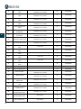
9 Unit Status ON/OFF
ACS
0
OFF
1 ON R 0x03, 0x04, 0x06, 0x10,
0x16
10 Status Power ACS
ON/OFF
0 OFF
1 ON R 0x03, 0x04, 0x06, 0x10,
0x16
11 Setpoint Water Setpoint x 10 R & W
0x03, 0x04, 0x06, 0x10,
0x16
12 Setpoint ACS Setpoint x 10 R & W
0x03, 0x04, 0x06, 0x10,
0x16
13 General Funct. Water
Unit
Bit 0
ACS unit available; 0: ACS Not
available; 1: ACS Available
Bit 1 Unit Water config TAI/TH; 0: TAI
mode; 1: TH mode
Bit 2 Válvula desviadora; 0: Position C/H;
1: Posición ACS
R 0x03, 0x04
14 Available Modes
Bit 0 Auto; Bit 1 Cool; Bit 2 Heat; Bit
3 Ventilation; Bit 4 Dry R 0x03, 0x04
15 Available Speeds
Bit 0
Auto; Bit 1
Super-Low; Bit 2
Low; Bit 3 Medium-Low; Bit 4
Medium; Bit 5 Medium-High; Bit 6
High; Bit 7 Super-High
R 0x03, 0x04
16 Available Louvers
Bit 0 Auto U/D; Bit 3 Swing U/D; Bit 4
Swing L/R; Bit 5 Swril; Bit 8-11
Vertical positions (0-7); Bit 12-15
Horizontal positions (0-7)
R 0x03, 0x04
17 Limit temp. Max Air
Cool
Limit x 10
Example: 23 ºC 230 R 0x03, 0x04

10
ES
EN
FR
IT
PT
DE
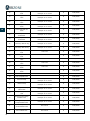
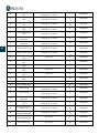
18 Limit temp. Min Air
Cool
Limit x 10
Example: 23 ºC 230 R 0x03, 0x04
19 Limit temp. Max Air
Heat
Limit x 10
Example: 23 ºC 230 R 0x03, 0x04
20 Limit temp. Min Air
Heat
Limit x 10
Example: 23 ºC 230 R 0x03, 0x04
21 Limit temp. Max Air
Auto
Limit x 10
Example: 23 ºC 230 R 0x03, 0x04
22 Limit temp. Min Air
Auto
Limit x 10
Example: 23 ºC 230 R 0x03, 0x04
23 Limit temp. Max Air
Ventilation
Limit x 10
Example: 23 ºC 230 R 0x03, 0x04
24 Limit temp. Min Air
Ventilation
Limit x 10
Example: 23 ºC 230 R 0x03, 0x04
25 Limit temp. Max Air Dry
Limit x 10
Example: 23 ºC 230 R 0x03, 0x04
26 Limit temp. Min Air Dry
Limit x 10
Example: 23 ºC 230 R 0x03, 0x04
27
Limit Temp Max Water
Cool Limit x 10 R 0x03, 0x04
28
Limit Temp Min Water
Cool Limit x 10 R 0x03, 0x04
29
Limit Temp Max Water
Heat Limit x 10 R 0x03, 0x04
30
Limit Temp Min Water
Heat Limit x 10 R 0x03, 0x04
31
Limit Temp Max Water
Auto Limit x 10 R 0x03, 0x04
32
Limit Temp Min Water
Auto Limit x 10 R 0x03, 0x04
33 Limit Temp Max ACS
Limit x 10
R 0x03, 0x04
34 Limit Temp Min ACS
Limit x 10
R 0x03, 0x04
35 External temp
Temp x 10
Example: 23 ºC 230 R 0x03, 0x04
36 Return Temp
Temp x 10
Example: 23 ºC 230 R 0x03, 0x04
37 Exchange Heat Temp
Indoor Unit
Temp x 10
Example: 23 ºC 230 R 0x03, 0x04
38 Gas Pipe Temp Indoor
Unit
Temp x 10
Example: 23 ºC 230 R 0x03, 0x04
39 Exchange Heat Temp
Outdoor Unit
Temp x 10
Example: 23 ºC 230 R 0x03, 0x04
40 Discharge Compressor
Temp Outdoor Unit
Temp x 10
Example: 23 ºC 230 R 0x03, 0x04
41
Position Expansion
Valve Outdoor Unit Pulse Units R 0x03, 0x04
42
Position Expansion
Valve Indoor Unit Pulse Units R 0x03, 0x04

11
ES
EN
FR
IT
PT
DE
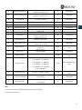
43 Pressure Evaporation
Pressure x 100
Example: 1.27 MPa 127 R 0x03, 0x04
44 Pressure Condensation
Pressure x 100
Example: 1.27 MPa 127 R 0x03, 0x04
45 Consumption
Consumption x 10
Exampe: 7 A 10 R 0x03, 0x04
46 Water Out Temp
Temp x 10
R 0x03, 0x04
47 Water In Temp
Temp x 10
R 0x03, 0x04
48 Deposit ACS Temp
Temp x 10
R 0x03, 0x04
49 Water Out Temp ICP
Temp x 10
R 0x03, 0x04
50 Refrigerant Temp
Temp x 10
R 0x03, 0x04
51 Water Flow
Water Flow x 10
Exampe: 7.2 l/min 72 R 0x03, 0x04
52 Water Pressure
Water Pressure x 10
Exampe: 1.3 bar 13 R 0x03, 0x04
53 Work Temperature
Temp x 10
Example: 23 ºC 230 R 0x03, 0x04
54 Speeds numeric
Auto
0; Silent
1; Low
2; Medium
3; High 4 R & W 0x03, 0x04, 0x06, 0x10,
0x16
55 Error value
Value of error
Example: 0x009
R
0x03, 0x04
56 Modbus address Modbus slave address (Default 1) R & W
0x03, 0x04, 0x06, 0x10,
0x16
57 Config. Baudrate
0 100 bps; 1 300 bps
2 500 bps; 3 1200 bps
4 2400 bps; 5 4800 bps
6 7800 bps; 7 9600 bps
8 19200 bps; 9 57600 bps
10 115200 bps
R & W 0x03, 0x04, 0x06, 0x10,
0x16
58 Config. Port parity 0 none, 1 Odd, 2 Even R & W
0x03, 0x04, 0x06, 0x10,
0x16
59 Emergency Heat status
0
Deactivated
1 Activated 0x03, 0x04
60 Input T1T2 status
0
Deactivated
1 Activated 0x03, 0x04
Notas:
(*) Los límites mínimo/máximo dependen de su unidad de A/C.
(**) Debe ser mayor que 0.
R
R

12
ES
EN
FR
IT
PT
DE
INDEX
Precautions and environmental policy ........................................................................................................................................................................... 13
Precautions ............................................................................................................................................................................................................................ 13
Environmental policy ........................................................................................................................................................................................................ 13
Connection ............................................................................................................................................................................................................................ 14
Modbus protocol ..................................................................................................................................................................................................................... 15
Configuration of the slave address for the Aidoo Wi-Fi/Pro controller device ........................................................................................... 15
Modbus function codes ......................................................................................................................................................................................................... 16
Modbus commands ................................................................................................................................................................................................................. 17
Write commands ................................................................................................................................................................................................................. 17
Write a single holding register ................................................................................................................................................................................ 17
Write multiple registers .............................................................................................................................................................................................. 17
Read command ................................................................................................................................................................................................................... 18
Question ........................................................................................................................................................................................................................... 18
Response .......................................................................................................................................................................................................................... 18
Registers ...................................................................................................................................................................................................................................... 19
System registers .................................................................................................................................................................................................................. 19

13
ES
EN
FR
IT
PT
DE
PRECAUTIONS AND ENVIRONMENTAL POLICY
PRECAUTIONS
For your security, and to protect the devices, follow these instructions:
• Do not manipulate the system with wet or damp hands.
• Disconnect the power supply before making any connections.
• Take care not to cause a short circuit in any of the system connections.
ENVIRONMENTAL POLICY
Do not dispose of this equipment in the household waste. Electrical and electronic
equipment contain substances that may damage the environment if they are not handled
appropriately. The symbol of a crossed-out waste bin indicates that electrical equipment
should be collected separately from other urban waste. For correct environmental
management, it must be taken to the collection centers provided for this purpose, at the end
of its useful life.
The equipment components may be recycled. Act in accordance with current regulations on
environmental protection.
If you replace it with other equipment, you must return it to the distributor or take it to a
specialized collection center.
Those breaking the law or by-laws will be subject to such fines and measures as are laid down
in environmental protection legislation.

14
ES
EN
FR
IT
PT
DE
RS-485 COMMUNICATION PORT
RS-485, also known as EIA-485, is a communication standard in bus.
Integration bus
Speed of the communication port
19200 bps
Communication
Half duplex
Frame length
8-bit
Stop bit
1-bit
Stream control
None
Parity
Even
CONNECTION
For proper operation of the system, verify that only the communication cables (green-
blue) are connected to their matching domotic buses. Attach the wires with the
terminal screws following the color code.

15
ES
EN
FR
IT
PT
DE
MODBUS PROTOCOL
MODBUS Protocol is a communication structure used to establish master-slave/client-server communication between
intelligent devices connected on different types of buses or networks.
Each device intended to communicate using Modbus is given a unique address. Master devices send a command in a frame
which contains the address of the device or the end-devices (slaves). All devices are sent the frame, but only the recipient
interprets and executes the command. Modbus commands contain checksum information, to allow the recipient to detect
transmission errors.
Note: It possible to send information to multiple devices simultaneously using a frame called "Broadcast".
Each message includes redundant information that ensures it is properly received. If, after a certain time, the master does not
receive a confirmation it interprets that an error has occurred and terminates communication.
The mode of transmission used is MODBUS-RTU. Each byte of data is represented by two 4-bit characters in hexadecimal format.
The format of the frame is the following:
Start
0
1
2
3
4
5
6
7
Parity
Stop
CONFIGURATION OF THE SLAVE ADDRESS FOR THE AIDOO WI-FI/PRO CONTROLLER DEVICE
The Aidoo is a Modbus slave device, so it is necessary to indicate its address. To do this, associate your Aidoo via the
"Airzone Aidoo" app (available for iOS and Android) by following these steps:
1. On the drop-down menu press the option Add device.
2. Select the unit from the list of available units to get info.
Note: If your unit does not appear, confirm the Bluetooth function of your iOS or Android is activated. Verify that the Aidoo
is working properly.
3. Enter the pin code located in the Aidoo if required and tap Send button.
4. You can start test actions to identify and check the operation of the unit (heating, cooling, fan and turning off).
5. Select Webserver information, configure the device's slave address in the Modbus port parameter and press the
validation icon.
6. Close the Webserver information window.
7. It will not be necessary to continue with the Add device process to integrate it via Modbus.

16
ES
EN
FR
IT
PT
DE
You can find the “Airzone Aidoo” app here:
https://www.airzonecontrol.com/ib/es/soluciones_de_control/aidoo/Wi-Fi
MODBUS FUNCTION CODES
Modbus basic commands allow the control of a device to change the value of its registers (memory slot) or to request the
content of these registers, depending on the codes:
Code
Function:
03
Read holding registers
04
Read input registers
06
Preset/write single holding register
16
Preset/write multiple holding registers

17
ES
EN
FR
IT
PT
DE
MODBUS COMMANDS
The format of the commands for the read/write operations is as follows (8 byte):
Slave
address
Operation
code
Register address Data CRC
1 byte
1 byte
2 bytes
1…2·N bytes
2 bytes
• Slave address Defines the system to access. A Modbus command contains the Modbus address of the device it is
intended for (1 to 247). 0 address is reserved for a transmission to all devices (broadcast).
• Operation code. Specifies the operation to be performed.
• Register address. Specifies the operation to be accessed. In commands to be performed in multiple registers,
defines the boot log, from which you want to operate consecutively.
• Data. Formed by 2 bytes (simple operations) or a set of 2 bytes (multiple operations) that contain the information
in the command.
• CRC. Two bytes are added to the end of the stream in order to detect transmission o reception errors. This action
is done using the Cyclic Redundant Code.
Generator polynomial: CRC-16 = x16 + x15 + x2 + 1.
WRITE COMMANDS
Write a single holding register
Byte
Field
0
Address of the slave (1-247) (0: Broadcast)
1
Write single register (6)
2
Register address
3
4
Data to be written
5
6
CRC
7
The response, as long as there is no error type, must be exactly the same format as the write command.
Write multiple registers
Byte
Field
0
Address of the slave (1-247) (0: Broadcast)
1
Write multiple register (16)
2
Starting register address
3
Number of registers to be written (N)
4
5
Total number of bytes of write data (2·N)
6
Data to be written in register 1
7
…
5+2·N
Data to be written in register N
6+2·N
7+2·N
CRC
8+2·N

18
ES
EN
FR
IT
PT
DE
The response, as long as it is error-free, will be:
Byte
Field
0
Address of the slave (1-247) (0: Broadcast)
1
Write multiple registers (16)
2
Starting register address
3
4
Number of registers to be written (N)
5
6
CRC
7
READ COMMAND
Question
Byte
Field
0
Address of the slave (1-247) (0: Broadcast)
1
Reading records (3/4)
2
Starting register address
3
4
Number of registers to be read (N)
5
6
CRC
7
Response
Byte
Field
0
Slave address (1-247) (0: Broadcast)
1
Read holding registers (3/4)
2
Number of response bytes (2·N)
3
Data to be read in register 0
4
…
3+2·N
Data to be read in register N
4+2·N
5+2·N
CRC
6+2·N

19
ES
EN
FR
IT
PT
DE
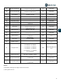
REGISTERS
SYSTEM REGISTERS
Registers Description Values
Read (R)
Write (W) Operations
0 On/Off
0 OFF
1 ON R & W
0x03, 0x04, 0x06, 0x10,
0x16
1 Setpoint* Setpoint x 10
Example: 22.5 ºC 225 R & W
0x03, 0x04, 0x06, 0x10,
0x16
2 Local temperature** Room Temperature x10 R & W
0x03, 0x04, 0x06, 0x10,
0x16
3 Modes 1 Auto; 2 Cooling; 3 Heating; 4
Fan; 5 Dry R & W
0x03, 0x04, 0x06, 0x10,
0x16
4 Speeds
0 Auto; 25 Silent; 50 Low;
75 Medium; 100 High R & W 0x03, 0x04, 0x06, 0x10,
0x16
5 Louver Vertical
0
Stop; 8
Auto pos;
9 Vertical auto Swing; 10 Swril pos R & W 0x03, 0x04, 0x06, 0x10,
0x16
6 Louver Horizontal
0 Stop; 8 Auto pos;
9 Horizontal auto Swing; 10 Swril pos R & W 0x03, 0x04, 0x06, 0x10,
0x16
7
Unit error code 1
(first part) Ascii value R 0x03, 0x04
8
Unit error code 2
(second part) Ascii value R 0x03, 0x04
9 Unit Status ON/OFF
ACS
0
OFF
1 ON R 0x03, 0x04, 0x06, 0x10,
0x16
10 Status Power ACS
ON/OFF
0 OFF
1 ON R 0x03, 0x04, 0x06, 0x10,
0x16
11 Setpoint Water Setpoint x 10 R & W
0x03, 0x04, 0x06, 0x10,
0x16
12 Setpoint ACS Setpoint x 10 R & W
0x03, 0x04, 0x06, 0x10,
0x16
13 General Funct. Water
Unit
Bit 0
ACS unit available; 0: ACS Not
available; 1: ACS Available
Bit 1 Unit Water config TAI/TH; 0: TAI
mode; 1: TH mode
Bit 2 Válvula desviadora; 0: Position C/H;
1: Posición ACS
R 0x03, 0x04
14 Available Modes
Bit 0 Auto; Bit 1 Cool; Bit 2 Heat; Bit
3 Ventilation; Bit 4 Dry R 0x03, 0x04
15 Available Speeds
Bit 0
Auto; Bit 1
Super-Low; Bit 2
Low; Bit 3 Medium-Low; Bit 4
Medium; Bit 5 Medium-High; Bit 6
High; Bit 7 Super-High
R 0x03, 0x04
16 Available Louvers
Bit 0 Auto U/D; Bit 3 Swing U/D; Bit 4
Swing L/R; Bit 5 Swril; Bit 8-11
Vertical positions (0-7); Bit 12-15
Horizontal positions (0-7)
R 0x03, 0x04
17 Limit temp. Max Air
Cool
Limit x 10
Example: 23 ºC 230 R 0x03, 0x04

20
ES
EN
FR
IT
PT
DE
18 Limit temp. Min Air
Cool
Limit x 10
Example: 23 ºC 230 R 0x03, 0x04
19 Limit temp. Max Air
Heat
Limit x 10
Example: 23 ºC 230 R 0x03, 0x04
20 Limit temp. Min Air
Heat
Limit x 10
Example: 23 ºC 230 R 0x03, 0x04
21 Limit temp. Max Air
Auto
Limit x 10
Example: 23 ºC 230 R 0x03, 0x04
22 Limit temp. Min Air
Auto
Limit x 10
Example: 23 ºC 230 R 0x03, 0x04
23 Limit temp. Max Air
Ventilation
Limit x 10
Example: 23 ºC 230 R 0x03, 0x04
24 Limit temp. Min Air
Ventilation
Limit x 10
Example: 23 ºC 230 R 0x03, 0x04
25 Limit temp. Max Air Dry
Limit x 10
Example: 23 ºC 230 R 0x03, 0x04
26 Limit temp. Min Air Dry
Limit x 10
Example: 23 ºC 230 R 0x03, 0x04
27
Limit Temp Max Water
Cool Limit x 10 R 0x03, 0x04
28
Limit Temp Min Water
Cool Limit x 10 R 0x03, 0x04
29
Limit Temp Max Water
Heat Limit x 10 R 0x03, 0x04
30
Limit Temp Min Water
Heat Limit x 10 R 0x03, 0x04
31
Limit Temp Max Water
Auto Limit x 10 R 0x03, 0x04
32
Limit Temp Min Water
Auto Limit x 10 R 0x03, 0x04
33 Limit Temp Max ACS
Limit x 10
R 0x03, 0x04
34 Limit Temp Min ACS
Limit x 10
R 0x03, 0x04
35 External temp
Temp x 10
Example: 23 ºC 230 R 0x03, 0x04
36 Return Temp
Temp x 10
Example: 23 ºC 230 R 0x03, 0x04
37 Exchange Heat Temp
Indoor Unit
Temp x 10
Example: 23 ºC 230 R 0x03, 0x04
38 Gas Pipe Temp Indoor
Unit
Temp x 10
Example: 23 ºC 230 R 0x03, 0x04
39 Exchange Heat Temp
Outdoor Unit
Temp x 10
Example: 23 ºC 230 R 0x03, 0x04
40 Discharge Compressor
Temp Outdoor Unit
Temp x 10
Example: 23 ºC 230 R 0x03, 0x04
41
Position Expansion
Valve Outdoor Unit Pulse Units R 0x03, 0x04
42
Position Expansion
Valve Indoor Unit Pulse Units R 0x03, 0x04
A página está carregando...
A página está carregando...
A página está carregando...
A página está carregando...
A página está carregando...
A página está carregando...
A página está carregando...
A página está carregando...
A página está carregando...
A página está carregando...
A página está carregando...
A página está carregando...
A página está carregando...
A página está carregando...
A página está carregando...
A página está carregando...
A página está carregando...
A página está carregando...
A página está carregando...
A página está carregando...
A página está carregando...
A página está carregando...
A página está carregando...
A página está carregando...
A página está carregando...
A página está carregando...
A página está carregando...
A página está carregando...
A página está carregando...
A página está carregando...
A página está carregando...
A página está carregando...
A página está carregando...
A página está carregando...
A página está carregando...
A página está carregando...
A página está carregando...
A página está carregando...
A página está carregando...
A página está carregando...
A página está carregando...
-
 1
1
-
 2
2
-
 3
3
-
 4
4
-
 5
5
-
 6
6
-
 7
7
-
 8
8
-
 9
9
-
 10
10
-
 11
11
-
 12
12
-
 13
13
-
 14
14
-
 15
15
-
 16
16
-
 17
17
-
 18
18
-
 19
19
-
 20
20
-
 21
21
-
 22
22
-
 23
23
-
 24
24
-
 25
25
-
 26
26
-
 27
27
-
 28
28
-
 29
29
-
 30
30
-
 31
31
-
 32
32
-
 33
33
-
 34
34
-
 35
35
-
 36
36
-
 37
37
-
 38
38
-
 39
39
-
 40
40
-
 41
41
-
 42
42
-
 43
43
-
 44
44
-
 45
45
-
 46
46
-
 47
47
-
 48
48
-
 49
49
-
 50
50
-
 51
51
-
 52
52
-
 53
53
-
 54
54
-
 55
55
-
 56
56
-
 57
57
-
 58
58
-
 59
59
-
 60
60
-
 61
61


Airzone KNX TP-1 Manual do usuário
- Categoria
- Condicionadores de ar de sistema split
- Tipo
- Manual do usuário
em outras línguas
- español: Airzone KNX TP-1 Manual de usuario
- français: Airzone KNX TP-1 Manuel utilisateur
- italiano: Airzone KNX TP-1 Manuale utente
Artigos relacionados
-
Airzone AZAI6WSPDKC Guia de usuario
-
 Airzone AZAI6WSCDKA Manual do usuário
-
Airzone AZAI6WSCPA0 Instruções de operação
-
 Airzone AZAI6WSCGR2 Guia de usuario
-
 Airzone IBPro6 Thermostat Wired Manual do usuário
-
Airzone MU AZ6 Manual do usuário
-
Airzone Aidoo Pro Manual do usuário
-
Airzone CB-ANT Manual do usuário


Outros documentos
-
ViewSonic LS625W Guia de usuario
-
ViewSonic LS700HD Guia de usuario
-
ViewSonic LS700-4K Guia de usuario
-
-
Daikin FWEC2 Manual do proprietário
-
ViewSonic PX727HD Guia de usuario
-
ViewSonic LS600W Guia de usuario
-
ViewSonic PX703HD Guia de usuario
-
ViewSonic X100-4K-S Guia de usuario
-
ViewSonic LS860WU-S Guia de usuario