
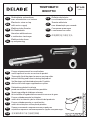
NT 445
Indice J
Robinetterie automatique
avec alimentation sur secteur
Electronic mixer or tap
with mains supply
Elektronische Armatur
für Netzbetrieb
Armatura elektroniczna
z zasilaniem sieciowym
Elektronische kraan
op netspanning
Grifería electrónica
con alimentación a red
Torneira eletrónica
com alimentação por corrente
Сенсорная арматура
с питанием от сети
带电源的电子感应龙头
DE
FR
EN
PL
NL
ES
PT
RU
CN
TEMPOMATIC
BINOPTIC
FR
EN
DE
PL
NL
ES
PT
RU
CN
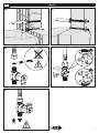
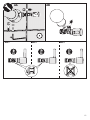
Purger soigneusement les canalisations
avant la pose et la mise en service du produit.
Thoroughly flush the pipes to remove any impurities
before installing and commissioning the product.
Vor Montage und Inbetriebnahme des Produkts
die Anschlussleitungen regelkonform spülen.
Dokładnie wypłukać instalację
przed montażem i uruchomieniem produktu.
Spoel zorgvuldig de leidingen alvorens
tot installatie of ingebruikname van de kraan over te gaan.
Purgar cuidadosamente las tuberías
antes de la instalación y de la utilización del producto.
Purgar cuidadosamente as canalizações
antes da instalação e utilização do produto.
Перед установкой и подключением устройства
тщательно промыть канализационные трубы напором воды.
在安装和调试产品之前清空管道 。

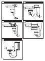
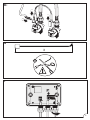
165
155
170
1/2"
110x75x40
17
200
1/2"
3/8"
Ø60
110x75x40
110 x 75 x 40
110 max
230
3/8"
205
190 max
Ø 40
1/2"
110x75x40
3/8"
185x160
70
225x200
14
110x75x40
240
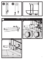
1 2
43
5
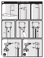
1

Ø 50
300
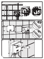
379ENC 379ENCB 379ENC15
1
C
A
Ø 32-38
B
2

150 mini
110 max
Ø35
Ø35
B
A2
C
Ø22
190 max
150 mini
A1A2
495612
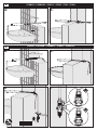
379MCH 379MCHB 379ECL 379EC 379C 379CL
379DER 379DERB 379DER15 379D13 379D1315
A1
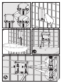
2
3
3

Ø22
Ø33
100 50
155 max
D
A2
B C
A1
441157
4
P. 8 4

Ø12
188
162
70
145
C
E FD
B
G H
A
447500 379ECM 379ECML
5
5

145
K L
I J
M
6

P Q
N O
R1
7

R2
S
X
T
8

U
V
W
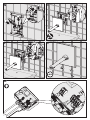
9

X1
X2
379MCH 379MCHB 379ECL 379EC 379C 379CL 379ENC 379ENCB
379DER 379D13 441157 447500 379ECM 379ECML
379DER15 379D1315 379ENC15
X3
10

Y
Z1
Z2
30
11

AA
AC1AC2AC3
AB
180°
12

AA AB
ADAC
AE
13

AF AG
AH
14

FONCTIONNEMENT
• Ouverture et fermeture automatiques par détection de présence des mains. Fermeture automatique
en cas de coupure d’électricité.
• Sécurité antiblocage : une temporisation de sécurité assure la fermeture après 30 secondes
d’écoulement, en cas de négligence ou d’obstacle situé dans le champ de détection.
Une fois l’obstacle retiré, le fonctionnement se réinitialise automatiquement.
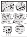
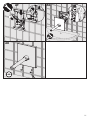
• Rinçage périodique antiprolifération bactérienne : purge automatique de ~ 60 secondes toutes
les 24 heures après la dernière utilisation (réglable sur 12h ou désactivable) : placer le cavalier en face
du programme souhaité (Fig. X2, X3).
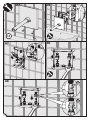
INSTALLATION
• Robinet : alimenter en eau froide ou mitigée.
• Mitigeur : alimenter en eau froide et en eau chaude à 70°C maximum (recommandée à 45°C pour
éviter les risques de brûlure) en équilibrant les pressions (P < 1 bar).
•Monter impérativement les joints filtres fournis. Ne pas ajouter de joint supplémentaire.
• Pression : 1 bar (100 kPa) à 5 bar (500 kPa), recommandée 3 bar (300 kPa). Différence de pression
aux entrées : 1 bar maxi.
• Pour éviter les interférences des rayons IR, ne pas installer deux robinetteries électroniques face à face
ou face à un miroir ou un objet brillant.
ALIMENTATION ELECTRIQUE
Boîtier électronique étanche IP65.
• Alimentation électrique en 100240 V / 5060 Hz classe II TBTS (sans prise de terre).
• L'installation doit être conforme aux normes en vigueur dans le pays (en France NF C 15100).
• Si le câble d’alimentation est endommagé, il doit être remplacé par l’installateur.
• Assurer la tenue des câbles par une pose fixe : colliers ou gaines rigides.
FR
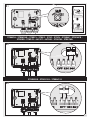
RACCORDEMENT
• Raccorder la/les électrovanne(s) à la borne EV via le joint caoutchouc du presse-étoupe :
- fil MARRON : borne EV+
- fil BLEU : borne EV-
• Raccorder le câble du détecteur sur la borne BMR via le joint caoutchouc du presse-étoupe :
- fil BLANC : borne B
- tresse de blindage : borne M
- fil ROUGE : borne R
• Il est conseillé de ne pas positionner les potentiomètres en butée minimum ou maximum.
RAPPEL
• Nos robinetteries doivent être installées par des installateurs professionnels en respectant
les réglementations en vigueur, les prescriptions des bureaux d'études fluides et les règles de l'art.
• Respecter le diamètre des tuyauteries permet d'éviter les coups de bélier ou pertes de pression/débit
(voir le tableau de calcul du catalogue et en ligne sur www.delabie.fr).
• Protéger l'installation avec des filtres, antibéliers ou réducteurs de pression diminue la fréquence
d'entretien (pression conseillée 1 à 5 bar (100 à 500 kPa)).
• Poser des vannes d'arrêt à proximité des robinets facilite l'intervention d'entretien.
• Les canalisations, filtres, clapets antiretour, robinets d'arrêt, de puisage, cartouche et tout appareil
sanitaire doivent être vérifiés au moins une fois par an et aussi souvent que nécessaire.
15

CHOCS THERMIQUE ET CHIMIQUE
Ce produit est conçu pour supporter les chocs thermique et chimique dans le cadre des réglementations
en vigueur.
MAINTENANCE
• Pour les versions mitigeurs, vérifier périodiquement et aussi souvent que nécessaire l’usure du sélecteur
de température ainsi que les 2 sièges internes du mitigeur sur lesquels tourne la clé de mélange.
Les remplacer si nécessaire.
• Les clapets antiretour doivent être vérifiés au moins une fois par an.
•Attention : ne jamais graisser l’intérieur du mécanisme.
FR
ENTRETIEN & NETTOYAGE
• Nettoyage du chrome, de l'aluminium et de l'Inox : ne jamais utiliser d'abrasifs ou tout autre
produit à base de chlore ou d'acide. Nettoyer à l'eau légèrement savonneuse avec un chiffon
ou une éponge.
• Mise hors gel : purger les canalisations et actionner plusieurs fois la robinetterie pour la vider
de son contenu d'eau. En cas d’exposition prolongée au gel, nous recommandons de démonter
les mécanismes et de les stocker à l’abri.
Service Après-Vente :
Tél. : + 33 (0)3 22 60 22 74 - e-mail : [email protected]
Notice disponible sur : www.delabie.fr 16

OPERATION
• Automatic open and closing with hand presence detection. Shut-off is automatic in the event
of electrical failure.
• Anti-blocking safety: a safety time flow guarantees shut-off after 30 seconds of flow, in the event
of negligence or an obstacle in the detection area. Once the obstacle is removed, operation will restart
automatically.
• Anti-bacterial proliferation duty flush: automatic flush ~60 seconds every 24 hours after the last use
(can be adjusted to 12h or deactivated): place the pin connectors facing the desired programme.
For all UK specific references the default setting for the duty flush feature is OFF (Fig. X2, X3).
INSTALLATION
• Tap: supply with cold or mixed water.
• Mixer: supply with cold and hot water up to 70°C maximum (we recommend 45°C to avoid the risk
of scalding) balancing the pressure (P < 1 bar).
•The filter seals supplied must be fitted. Do not fit additional seals.
• Pressure: 1 bar (100 kPa) to 5 bar (500 kPa), recommended 3 bar (300 kPa). Pressure difference
at inlets: 1 bar maximum.
• To avoid interference with infrared rays, do not install two electronic taps/mixers facing each other
or bright objects.
ELECTRICAL SUPPLY
IP65 waterproof electronic housing.
• Electrical supply 100240V / 5060Hz class II TBTS SELV (separated from earth).
• The installation must conform to local Electrical Regulations/Standards and must be installed by
a competent, qualified electrician.
• If the supply cable is damaged, the installer must replace it.
• Secure the cables in place with a fixed router e.g. a rigid sheath or cable holder.
EN
CONNECTIONS
• Connect the solenoid valve(s) to the EV terminal through the cable gland’s rubber seal:
- BROWN wire: EV+ terminal
- BLUE wire: EV- terminal
• Connect the sensor cable to the BMR terminal through the cable gland’s rubber seal:
- WHITE wire: B terminal
- shielding braid: M terminal
- RED wire: R terminal
• Placing the potentiometers in the minimium or maximum position is not advised.
REMEMBER
• Our mixers/taps must be installed by professional installers in accordance with current
regulations and recommendations in your country, and the specifications of the fluid engineer.
• Sizing the pipes correctly will avoid problems of flow rate, pressure loss and water hammer
(see calculation table in our brochure and online at www.delabie.com).
• Protect the installation with filters, water hammer absorbers and pressure reducers to reduce
the frequency of maintenance (recommended pressure from 1 to 5 bar (100 to 500 kPa) maximum).
• Install stopcocks close to the mixer/tap to facilitate maintenance.
• The pipework, filters, non-return valves, stopcocks, bib taps, cartridge and all sanitary fittings should
be checked at least once a year, and more frequently if necessary.
17

CHEMICAL & THERMAL SHOCKS
This product has been designed to withstand both thermal and chemical shocks in line with current
regulations.
MAINTENANCE
• For the mixer versions, periodically check, and as often as necessary, the temperature selector
and the mixer's two internal seats on which the mixing key turns.
Replace them if necessary.
• The non-return valves must be checked at least once a year.
•Warning: never grease the interior of the mechanism.
EN
MAINTENANCE & CLEANING
• Cleaning chrome, aluminium and stainless steel: do not use abrasive, chlorine or any other
acid-based cleaning products. Clean with mild soapy water using a cloth or a sponge.
• Frost protection: drain the pipes and operate the mixer/tap/valve several times to drain any
remaining water. In the event of prolonged exposure to frost, we recommend taking the mechanisms
apart and storing them indoors.
After Sales Care Support:
For the UK market only: Tel. 01491 821 821 - email: [email protected]
The installation guide is available on: www.delabie.co.uk
The installation guide is available on: www.delabie.com 18

FUNKTIONSWEISE
• Automatisches Öffnen und Schließen durch Erfassung der Hände im Sensorbereich. Automatisches
Schließen bei Stromausfall.
• Antiblockiersicherheit: Sicherheits-Timeout gewährleistet das Schließen der Armatur nach 30 Sekunden
Dauerlauf bei Nachlässigkeit oder Hindernis im Erfassungsbereich. Automatische Reinitialisierung des
Betriebsmodus, sobald das Hindernis entfernt wurde.
• Hygienespülung zur Begrenzung des Bakterienwachstums: automatische Spülung von ~60 Sekunden
alle 24 Stunden nach der letzten Nutzung (einstellbar auf 12 h oder deaktivierbar): Reiter auf die
Position des gewünschten Programms stecken (Abb. X2, X3).
INSTALLATION
• Ventil: Anschluss an Kalt- oder Mischwasser.
• Mischbatterie: Anschluss an Kalt- und Warmwasser von maximal 70 °C (Gemäß DIN EN 8062 und
VDI Richtlinie 3818 ist die Auslauftemperatur auf maximal 38 °C bzw. 40 °C zu begrenzen, um
Verbrühungsrisiken zu begrenzen) und Druckdifferenz ausgleichen (P < 1 bar).
•Mitgelieferte Siebdichtungen unbedingt montieren. Keine zusätzliche Dichtung hinzufügen.
• Fließdruck: 1 bar (100 kPa) bis 5 bar (500 kPa), 3 bar empfohlen (300 kPa). Eingangsseitige
Druckdifferenz: max. 1 bar.
• Zur Vermeidung von Interferenzen der Infrarotstrahlen: die Sensor-Armatur nicht gegenüber eines
Spiegels oder eines spiegelnden Gegenstands installieren. Zwei Sensor-Armaturen nicht einander
gegenüber installieren.
STROMVERSORGUNG
Strahlwassergeschützte Elektronik-Box IP65
• Stromversorgung 100240 V / 5060 Hz Klasse II Sicherheitskleinspannung [SELV] (ohne Erdleitung).
• Die Installation muss den im jeweiligen Land gültigen Normen entsprechen (in Deutschland:
DIN 57100/VDE 100 Teil 701).
• Wenn das Anschlusskabel beschädigt ist, muss dieses durch den Installateur ersetzt werden.
• Halt der Kabel durch festes Verlegen gewährleisten (Schelle oder starre Kabelkanäle).
DE
HINWEIS
• Einbau und Inbetriebnahme unserer Armaturen müssen von geschultem Fachpersonal
unter Berücksichtigung der allgemein anerkannten Regeln der Technik durchgeführt werden.
• Angemessene Leitungsquerschnitte verhindern Wasserschläge oder Druck-/Durchflussverluste
• Die Absicherung der Installation mit Vorfiltern, Wasserschlag- oder Druckminderern reduziert die
Wartungshäufigkeit (empfohlener Betriebsdruck 1 bis 5 bar (100 bis 500 kPa)).
• Vorgelagerte Absperrventile erleichtern die Wartung.
• Rohrleitungen, Schutzfilter, Rückflussverhinderer, Vorabsperrungen, Auslaufventile, Kartusche und
jede sanitäre Einrichtung müssen so oft wie nötig (mindestens einmal jährlich) überprüft werden.
ANSCHLU SS
• Magnetventil(e) über die Gummidichtung der Kabelverschraubung an die Klemme EV anschließen:
- BRAUNER Draht: Klemme EV+
- BLAUER Draht: Klemme EV-
• Sensorkabel über die Gummidichtung der Kabelverschraubung an die Klemme BMR anschließen:
- WEISSER Draht: Klemme B
- Abgeschirmtes Kabel: Klemme M
- ROTER Draht: Klemme R
• Wir empfehlen, die Potentiometer nicht am Minimal- oder Maximalanschlag zu positionieren.
19
A página está carregando...
A página está carregando...
A página está carregando...
A página está carregando...
A página está carregando...
A página está carregando...
A página está carregando...
A página está carregando...
A página está carregando...
A página está carregando...
A página está carregando...
A página está carregando...
A página está carregando...
-
 1
1
-
 2
2
-
 3
3
-
 4
4
-
 5
5
-
 6
6
-
 7
7
-
 8
8
-
 9
9
-
 10
10
-
 11
11
-
 12
12
-
 13
13
-
 14
14
-
 15
15
-
 16
16
-
 17
17
-
 18
18
-
 19
19
-
 20
20
-
 21
21
-
 22
22
-
 23
23
-
 24
24
-
 25
25
-
 26
26
-
 27
27
-
 28
28
-
 29
29
-
 30
30
-
 31
31
-
 32
32
-
 33
33


