
DOC026.97.80437
SD900 Portable Sampler
02/2015, Edition 2
Basic User Manual
Manuel d'utilisation de base
Manual básico del usuario
Manual Básico do Usuário
基本用户手册
基本取扱説明書
기본 사용 설명서

English..............................................................................................................................3
Français......................................................................................................................... 28
Español.......................................................................................................................... 54
Português...................................................................................................................... 80
中文............................................................................................................................... 106
日本語........................................................................................................................... 129
한글............................................................................................................................... 153
2

Table of contents
Specifications on page 3 Operation on page 17
General information on page 5 Maintenance on page 23
Installation on page 8
Additional information
Additional information is available on the manufacturer's website.
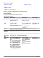
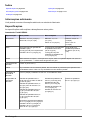
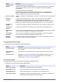
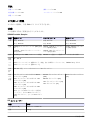
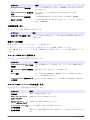
Specifications
Specifications are subject to change without notice.
SD900 Portable Sampler
Specification Standard base Compact base Composite base
Dimensions Diameter: 50.5 cm (19.9 in.)
Height: 69.4 cm (27.3 in.)
Diameter: 44.1 cm (17.4 in.)
Height: 61 cm (24 in.)
Diameter: 50.28 cm
(19.8 in.)
Height: 79.75 cm
(31.4 in.)
Weight 15 kg (35.6 lb) with 1-L
polyethylene bottles (24x)
14.8 kg (32.6 lb) with 10-L (2.5 gal)
polyethylene container (1x)
12.2 kg (27 lb) with 575-mL
(19.44 oz) polyethylene
bottles (24x)
12.9 kg (28.3 lb) with 10-L
(2.5 gal) polyethylene
container (1x)
15 kg (36 lb) with 950-
mL (32.12 oz) glass
bottles (12x)
Enclosure Impact-resistant ABS, 3-section construction; double-walled base with 2.54 cm (1 in.)
insulation—direct bottle contact with ice.
Sample
temperature
0–60 °C (32–140 °F)
Strainers 316 stainless steel in standard size, high velocity or low profile for shallow depth applications
and Teflon
®
or 316 stainless steel in standard size
Sample intake
tubing
9.5 mm (3/8 in.) I.D. vinyl or Teflon-lined polyethylene
Sample bottle
capacity
1-L (0.26 gal) polyethylene and/or
350-mL (11.83 oz) glass bottles
(24x)
2.3-L (0.6 gal) polyethylene and/or
1.9-L (0.5 gal) glass bottles (8x)
3.8-L (1 gal) polyethylene and/or
3.8-L (1 gal) glass bottles (4x)
3.8-L (1 gal) polyethylene and/or
3.8-L (1 gal) glass bottles (2x)
21-L (5.5 gal) or 15-L (4 gal)
polyethylene composite container
or 20-L (5.25 gal) polyethylene or
10-L (2.5 gal) polyethylene or 10-L
(2.5 gal) glass (1x)
575-mL (19.44 oz)
polyethylene bottles (24x)
950-mL (32.12 oz) glass
bottles (8x)
10-L (2.5 gal) polyethylene
bottle (1x)
10-L (2.5 gal) glass bottle
(1x)
21-L (5.5 gal)
polyethylene bottle (1x)
English 3

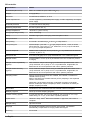
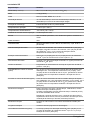
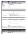
SD controller
Specification Details
Dimensions (W x H x D) 29.2 x 17.1 x 26.4 cm (11½ x 6¾ x 10
3
/
8
in.)
Weight 4.2 kg (9.26 lb)
Enclosure PC/ABS blend, NEMA 4X, 6, IP 67
Power requirements 15 VDC supplied by a 8754500 power supply; 15 VDC supplied by an integral
power supply
Overload protection 7 A, DC line fuse for the pump
Operating temperature 0 to 50 °C (32 to 122 °F)
Storage temperature –30 to 60 °C (–22 to 140 °F)
Storage/operating humidity 100% condensing
Pump Peristaltic high speed, with spring-mounted Nylatron rollers
Pump enclosure IP37
Pump tubing 9.5 mm ID x 15.9 OD mm (
3
/
8
in. ID x
5
/
8
in. OD) silicone
Pump tubing life 20,000 sample cycles with: 1 L (0.3 gal) sample volume, 1 rinse, 6 minute
pacing interval, 4.9 m (16 ft) of
3
/
8
in. intake tube, 4.6 m (15 ft) of vertical lift,
21 °C (70 °F) sample temperature
Vertical sample lift Maximum 8.5 m (28 ft) for: 8.8 m (29 ft) of
3
/
8
-in. vinyl intake tube at sea level
at 20–25 °C (68–77 °F)
Pump flow rate 4.8 L/min (1.25 gpm) at 1 m (3 ft) vertical lift with
3
/
8
-in. intake tube typical
Sample volume Programmable in 10-mL (0.34 oz) increments from 10 to 10,000 mL (3.38 oz
to 2.6 gal)
Sample volume repeatability
(typical)
±5% of 200 mL sample volume using uncalibrated liquid detect with: 4.6 m
(15 ft) vertical lift, 4.9 m (16 ft) of
3
/
8
-in. vinyl intake tube, single bottle, full
bottle shut-off at room temperature and 1524 m (5000 ft) elevation
Sample volume accuracy
(typical)
±10% of 200 mL sample volume using uncalibrated liquid detect with: 4.6 m
(15 ft) vertical lift, 4.9 m (16 ft) of
3
/
8
-in. vinyl intake tube, single bottle, full
bottle shut-off at room temperature and 1524 m (5000 ft) elevation
Sampling modes Pacing: Time-fixed, flow-fixed, time-variable, flow-variable, constant time
variable volume (CTVV).
Refer to Constant Time Variable Volume (CTVV) sampling in the expanded
version of this manual.
Distribution: Single bottle composite, multi-bottle composite, multi-bottle
discrete, bottles per sample, samples per bottle, combination of bottles per
sample, samples per bottle
Run modes Continuous or non-continuous with user-entered number of samples
Multiple programs Stores up to three sampling programs
Transfer velocity (typical) 0.9 m/s (2.9 ft/s) with: 4.6 m (15 ft) vertical lift, 4.9 m (16 ft) of
3
/
8
-in. vinyl
intake tubing, 21 °C (70 °F) and 1524 m (5000 ft) elevation
Liquid sensor Ultrasonic. Body: Ultem
®
NSF ANSI standard 51 approved, USP Class VI
compliant
Sample history Up to 510 records
Air purge Air purged automatically before and after each sample. The duration
automatically compensates for varying intake tube lengths.
Event log 510 records
4 English

Specification Details
Connections Power, auxiliary, serial communications, distributor, SDI-12
Wetted materials Stainless steel, polyethylene, Teflon, Ultem, silicone
Communications RS232, Modbus, SDI-12
Warranty 1 year
General information
In no event will the manufacturer be liable for direct, indirect, special, incidental or consequential
damages resulting from any defect or omission in this manual. The manufacturer reserves the right to
make changes in this manual and the products it describes at any time, without notice or obligation.
Revised editions are found on the manufacturer’s website.
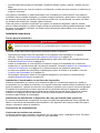
Safety information
N O T I C E
The manufacturer is not responsible for any damages due to misapplication or misuse of this product including,
without limitation, direct, incidental and consequential damages, and disclaims such damages to the full extent
permitted under applicable law. The user is solely responsible to identify critical application risks and install
appropriate mechanisms to protect processes during a possible equipment malfunction.
Please read this entire manual before unpacking, setting up or operating this equipment. Pay
attention to all danger and caution statements. Failure to do so could result in serious injury to the
operator or damage to the equipment.
Make sure that the protection provided by this equipment is not impaired. Do not use or install this
equipment in any manner other than that specified in this manual.
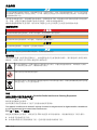
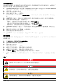
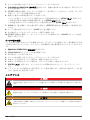
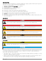
Use of hazard information
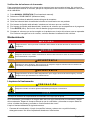
D A N G E R
Indicates a potentially or imminently hazardous situation which, if not avoided, will result in death or serious injury.
W A R N I N G
Indicates a potentially or imminently hazardous situation which, if not avoided, could result in death or serious
injury.
C A U T I O N
Indicates a potentially hazardous situation that may result in minor or moderate injury.
N O T I C E
Indicates a situation which, if not avoided, may cause damage to the instrument. Information that requires special
emphasis.
English 5

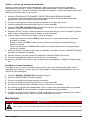
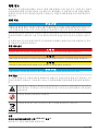
Precautionary labels
Read all labels and tags attached to the instrument. Personal injury or damage to the instrument
could occur if not observed. A symbol on the instrument is referenced in the manual with a
precautionary statement.
This is the safety alert symbol. Obey all safety messages that follow this symbol to avoid potential
injury. If on the instrument, refer to the instruction manual for operation or safety information.
This symbol indicates a potential pinch hazard.
Electrical equipment marked with this symbol may not be disposed of in European domestic or public
disposal systems. Return old or end-of-life equipment to the manufacturer for disposal at no charge to
the user.
Certification
Canadian Radio Interference-Causing Equipment Regulation, IECS-003, Class A:
Supporting test records reside with the manufacturer.
This Class A digital apparatus meets all requirements of the Canadian Interference-Causing
Equipment Regulations.
Cet appareil numérique de classe A répond à toutes les exigences de la réglementation canadienne
sur les équipements provoquant des interférences.
FCC Part 15, Class "A" Limits
Supporting test records reside with the manufacturer. The device complies with Part 15 of the FCC
Rules. Operation is subject to the following conditions:
1. The equipment may not cause harmful interference.
2. The equipment must accept any interference received, including interference that may cause
undesired operation.
Changes or modifications to this equipment not expressly approved by the party responsible for
compliance could void the user's authority to operate the equipment. This equipment has been tested
and found to comply with the limits for a Class A digital device, pursuant to Part 15 of the FCC rules.
These limits are designed to provide reasonable protection against harmful interference when the
equipment is operated in a commercial environment. This equipment generates, uses and can
radiate radio frequency energy and, if not installed and used in accordance with the instruction
manual, may cause harmful interference to radio communications. Operation of this equipment in a
residential area is likely to cause harmful interference, in which case the user will be required to
correct the interference at their expense. The following techniques can be used to reduce
interference problems:
1. Disconnect the equipment from its power source to verify that it is or is not the source of the
interference.
2. If the equipment is connected to the same outlet as the device experiencing interference, connect
the equipment to a different outlet.
3. Move the equipment away from the device receiving the interference.
4. Reposition the receiving antenna for the device receiving the interference.
5. Try combinations of the above.
6
English

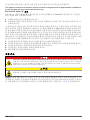
Product overview
D A N G E R
Chemical or biological hazards. If this instrument is used to monitor a treatment process and/or
chemical feed system for which there are regulatory limits and monitoring requirements related to
public health, public safety, food or beverage manufacture or processing, it is the responsibility of the
user of this instrument to know and abide by any applicable regulation and to have sufficient and
appropriate mechanisms in place for compliance with applicable regulations in the event of malfunction
of the instrument.
C A U T I O N
Fire hazard. This product is not designed for use with flammable liquids.
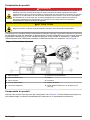
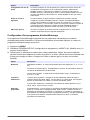
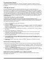
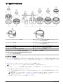
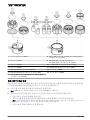
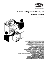
The SD900 Portable Sampler collects liquid samples at specified intervals and keeps the samples in
bottles or containers. Use the sampler for a wide variety of aqueous applications and for toxic
pollutants and suspended solids. Set up the sampler with different retainers, bottles or containers.
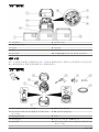
Refer to Figure 1.
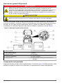
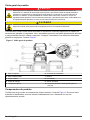
Figure 1 Product overview
1 Compact base 6 Controller connections
2 Standard insulated base 7 Pump
3 Center section 8 Controller
4 Power source 9 Liquid sensor
5 Top cover 10 Standard insulated base for 21-L (5.5 gal)
container
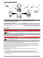
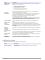
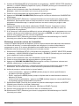
Product components
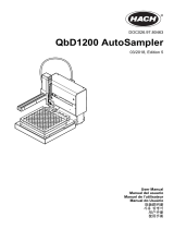
Make sure that all components have been received. Refer to Figure 2. If any items are missing or
damaged, contact the manufacturer or a sales representative immediately.
English
7

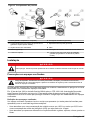
Figure 2 Product components
1 Base (Standard, compact or composite) 6 Battery charger (optional)
2 Components for a single-bottle option (bottle and
support can change)
7 AC power supply (optional)
3 Center section with controller 8 Strainer
4 Battery (optional) 9 Intake tubing, vinyl or Teflon-lined
5 Top cover 10 Components for a multiple-bottle option (bottles
and retainers can change)
Installation
D A N G E R
Multiple hazards. Only qualified personnel must conduct the tasks described in this section of the
document.
Confined space precautions
D A N G E R
Explosion hazard. Training in pre-entry testing, ventilation, entry procedures, evacuation/rescue
procedures and safety work practices is necessary before entering confined spaces.
The information that follows is supplied to help users understand the dangers and risks that are
associated with entry into confined spaces.
On April 15, 1993, OSHA's final ruling on CFR 1910.146, Permit Required Confined Spaces, became
law. This standard directly affects more than 250,000 industrial sites in the United States and was
created to protect the health and safety of workers in confined spaces.
Definition of a confined space:
A confined space is any location or enclosure that has (or has the immediate potential for) one or
more of the following conditions:
• An atmosphere with an oxygen concentration that is less than 19.5% or more than 23.5% and/or a
hydrogen sulfide (H
2
S) concentration that is more than 10 ppm.
• An atmosphere that can be flammable or explosive due to gases, vapors, mists, dusts or fibers.
• Toxic materials which upon contact or inhalation can cause injury, impairment of health or death.
8
English

Confined spaces are not designed for human occupancy. Confined spaces have a restricted entry
and contain known or potential hazards. Examples of confined spaces include manholes, stacks,
pipes, vats, switch vaults and other similar locations.
Standard safety procedures must always be obeyed before entry into confined spaces and/or
locations where hazardous gases, vapors, mists, dusts or fibers can be present. Before entry into a
confined space, find and read all procedures that are related to confined space entry.
Mechanical installation
Site installation guidelines
D A N G E R
Explosion hazard. The instrument is not approved for installation in hazardous locations.
Refer to the guidelines that follow for the site location evaluation.
• Obey all the safety precautions if the sampler is installed in a confined space. Refer to Confined
space precautions on page 8.
• Make sure that the temperature at the location is in the specification range. Refer to Specifications
on page 3.
• Install the sampler on a level surface or hang the sampler with the suspension harness, the
support bracket or the spanner bar. Refer to Install the sampler in a manhole on page 9 and to
the applicable installation documentation.
• As near the sample source as possible to decrease analysis delay. Refer to Plumb the sampler
on page 12.
• For limitations on transport velocity and maximum vertical lift, refer to Specifications on page 3.
Install the sampler in a manhole
Install the sampler above the sample water in a manhole. Install the sampler with a spanner bar or a
support bracket. Install the spanner bar inside the manhole. The spanner bar is supported by
pressure against the walls. The support bracket has the same width as the manhole cover. Install the
support bracket directly below the cover for support.Refer to the expanded manual on the
manufacturer's website.Refer to the documentation supplied with the accessories to install the
sampler.
Install the distributor or full-bottle shutoff (optional)
The distributor or full-bottle shutoff assembly is typically installed at the factory. Refer to the
distributor or full-bottle shutoff documentation for installation.
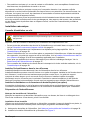
Prepare the sampler
Clean the sample bottles
Clean the sample bottles and caps with a brush, water and a mild detergent. Flush the containers
with fresh water followed by a distilled water rinse.
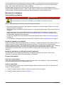
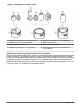
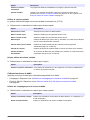
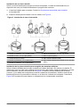
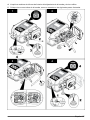
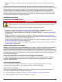
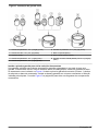
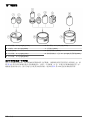
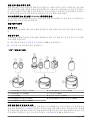
Install a single bottle
Use a single bottle to collect one composite sample. When the bottle is full, the full bottle shut-off
stops the sample program.
1. Clean the sample bottles. Refer to Clean the sample bottles on page 9.
2. Install the sample bottle as shown in Figure 3.
English
9

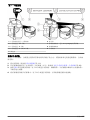
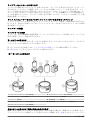
Figure 3 Single bottle installation
1 Polyethylene bottle, 10 L (2.5 gal) (1918) 6 Polyethylene bottle, 21 L (5.5 gal) (6494)
2 Glass bottle, 10 L (2.5 gal) (6559) 7 Compact base (8975)
3 Support (1502) 8 Standard insulated base (8976)
4 Polyethylene bottle, 15 L (4 gal) (1367) 9 Standard insulated base for 21 L (5.5 gal) bottle
(8561)
5 Polyethylene bottle, 19 L (5 gal) (6498)
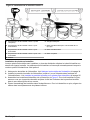
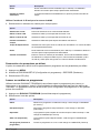
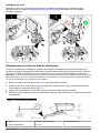
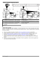
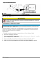
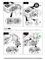
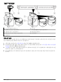
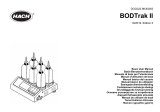
Install the first bottle for multiple sample collections
Use multiple bottles to collect samples into separate bottles or into more than one bottle. The
distributor moves the sample tube above each bottle. Install the bottles in the sampler base as shown
in Figure 4. Install the first sample bottle (number 1) below the label in the sampler base. Install the
remaining bottles in increasing numbers in the direction shown by the label. Refer to Figure 5
on page 12 for a diagram of necessary components.
10
English

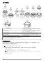
Figure 4 Bottle number 1 installation
1 Bottle number 1 location (compact base) 6 Elastic straps
2 Bottle number 1 location for 24 bottles 7 Standard insulated base for 21 L (5.5 gal) bottle
3 Bottle number 1 location for 8 bottles 8 Standad insulated base
4 Bottle number 1 location for 2 or 4 bottles 9 Compact base
5 Retainer
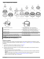
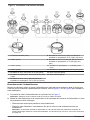
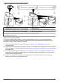
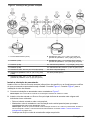
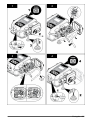
Install multiple bottles
When multiple bottles are installed, a distributor arm moves the sample tube over each bottle.
Sample collection automatically stops when the specified number of samples have been collected.
1. Clean the sample bottles. Refer to Clean the sample bottles on page 9.
2. Install the first sample bottle (number 1) below the label in the sampler base. Refer to Install the
first bottle for multiple sample collections on page 10.
3. Assemble the sample bottles as shown in Figure 5. For eight or more bottles, make sure that the
first bottle goes next to the bottle one indicator in the clockwise direction.
4. Put the bottle assembly in the sampler. For eight or more bottles, align the wires in the slots in the
bottom tray.
English
11

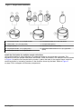
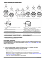
Figure 5 Multiple bottle installation
1 Positioner/retainer (2347) 8 Glass bottles, 3.8 L (1 gal), (4x) (2216) or
polyethylene bottles, 3.8 L (1 gal), (4x) (2217)
2 Retainer (1422) 9 Glass bottles, 1.9 L (0.5 gal), (8x) (1118) or
polyethylene bottles, 2.3 L (0.61 gal), (8x) (657)
3 Retainer (2190) 10 Polyethylene bottles, 1 L (0.26 gal), (24x) (737)
4 Retainer (2189) 11 Glass bottles, 350 mL (11.83 oz), (24x) (732)
5 Glass bottles, 950 mL (32.12 oz) (8x) (2348) 12 Compact base (8975)
6 Polyethylene bottles, 575 mL (19.44 oz), (24x)
(1369)
13 Standard base (8976)
7 Glass bottles, 3.8 L (1 gal), (2x) (2214) or
polyethylene bottles, 3.8 L (1 gal), (2x) (2215)
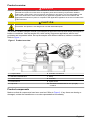
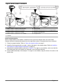
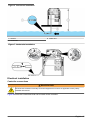
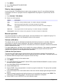
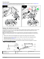
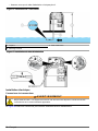
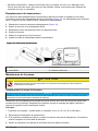
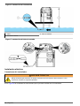
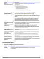
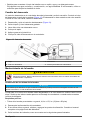
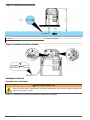
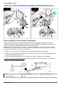
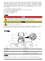
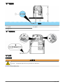
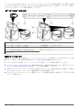
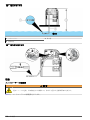
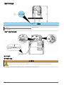
Plumb the sampler
Install the strainer in the middle of the sample stream (not near the surface or the bottom) to make
sure that a representative sample is collected. Refer to Figure 6. Refer to Figure 7 for the intake tube
installation.
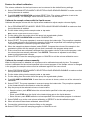
1. Connect the tubing to the sampler as shown in Figure 7.
Note: Use connection kit 2186 if Teflon-lined tubing is used.
2. Install the intake tube and strainer in the main stream of the sample source where the water is
turbulent and well-mixed.
• Make the intake tube as short as possible.
• Keep the intake tube at a maximum vertical slope so that the tube drains completely between
samples.
Note: If a vertical slope is not possible or if the tube is pressurized, disable the liquid sensor. Calibrate the
sample volume manually. Refer to Calibrate the sample volume manually on page 22.
• Make sure that the intake tube is not pinched.
12
English

Figure 6 Instrument installation
1 Strainer 3 Intake tube
2 Vertical lift
Figure 7 Intake tube installation
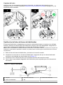
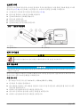
Electrical installation
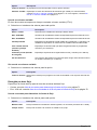
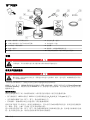
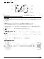
Controller connections
W A R N I N G
Electrical shock hazard. Externally connected equipment must have an applicable country safety
standard assessment.
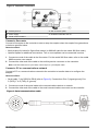
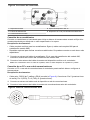
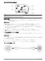
Figure 8 shows the connections that can be made to the controller.
English
13

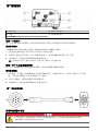
Figure 8 Controller connectors
1 Auxiliary device 4 SDI-12 device option
2 Power supply 5 Distributor/full bottle shut-off
3 Serial communications
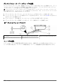
Connect a flow meter
Connect a flow meter to the controller to start or stop the sampler when the sample flow goes above
or below a specified value.
Items to collect:
• Multi-purpose full cable for Sigma flow meters (or 980 half cable for the model 980 flow meter).
• Optional splitter for additional connections. Two or more splitters can be connected in series.
1. Connect one end of the cable to the flow meter. For the model 980 flow meter, refer to the model
980 flow meter user manual.
2. Connect the other end of the cable to the auxiliary device connector on the controller.
Note: If the flow meter has a 6-pin cable, use the 6-pin to 7-pin adapter cable.
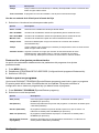
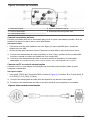
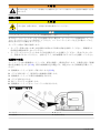
Connect a PC or communications network
Connect a PC or a communications network to the controller to transfer data or to configure the
sampler.
Items to collect:
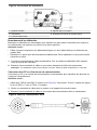
• Serial cable, 7-pin RS232 to DB-9 (refer to Figure 9). Connections: B to 5 (signal ground); D to
3 (RCD); F to 2 (TXD); G (ground).
1. Connect one end of the serial cable to the communications device or network.
2. Connect the other end of the cable to the serial communications connector on the controller.
Figure 9 Serial communications cable
14 English

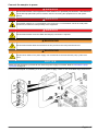
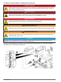
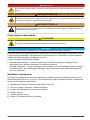
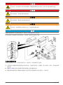
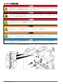
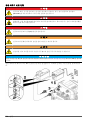
Connect the sampler to power
D A N G E R
Electrocution hazard. If this equipment is used outdoors or in potentially wet locations, a Ground Fault
Circuit Interrupt (GFCI/GFI) device must be used for connecting the equipment to its main power
source.
D A N G E R
Fire hazard. Install a 15 A circuit breaker in the power line. A circuit breaker can be the local power
disconnect, if located in close proximity to the equipment.
D A N G E R
Electrocution hazard. Protective Earth Ground (PE) connection is required.
W A R N I N G
Electrocution hazard. Make sure that there is easy access to the local power disconnect.
W A R N I N G
Electric shock hazard. The power supply can overheat when the time between pump cycles is too
short.
N O T I C E
Make sure that the pump cycle time will not cause the power supply to overheat. Refer to Calculate the pump
cycle time on page 16.
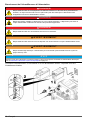
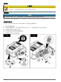
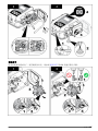
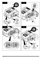
Connect the sampler to a battery or to an AC power supply. Refer to the illustrated steps that follow.
English
15

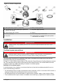
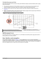
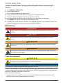
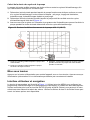
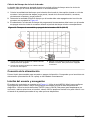
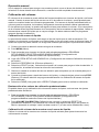
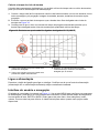
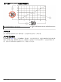
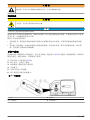
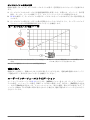
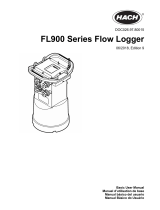
Calculate the pump cycle time
The pump must stay off for a minimum time period between sample cycles so that the power supply
does not overheat.
1. Calculate the total amount of time that the pump will run continuously during a sample cycle.
Include all stages: pre-purge, intake rinse, sample, sample retries and post-purge.
2. Find the minimum amount of time that the pump must stay off between sample cycles from
Figure 10.
3. Make sure that the pacing or time interval in the sampler program lets the pump stay off between
sample cycles for the minimum amount of time.
Figure 10 Pump on and off times at 50 °C (122 ºF)
1 Time (in minutes) that the pump must stay off 3 Example: if the pump is on continuously for
5 minutes, the pump must stay off for 15 minutes.
2 Time (in minutes) that the pump is on continuously
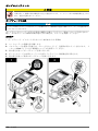
Set the power to on
Push the power button to set the power to on or off. Make sure that the power supply (AC power or
battery power) is correctly installed.
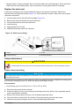
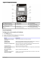
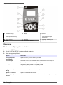
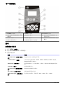
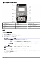
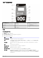
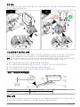
User interface and navigation
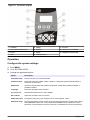
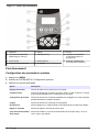
The controller keypad is shown in Figure 11. Use the MENU key to set up sampling programs,
configure the controller settings or complete the diagnostic tests. Use the arrows, ENTER and BACK
keys to scroll through the menu, make selections and enter values. Look for arrows on the bottom or
side of the display screen to know when more options are available.
16
English

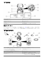
Figure 11 Controller keypad
1 POWER 5 MENU 9 STATUS
2 VOLUME CALIBRATION 6 ENTER 10 RUN/HALT PROGRAM
3 STOP 7 BACK 11 MANUAL OPERATION
4 LED 8 ARROW KEYS
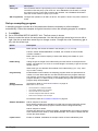
Operation
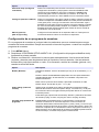
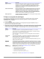
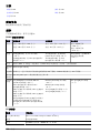
Configure the system settings
1. Push MENU.
2. Go to SYSTEM SETUP.
3. Change the applicable options.
Option Description
Time/date setup Set the time (24-hour format) and date.
Communication Select the baud rate (19200, 38400, 57600 or 115200) and protocol (Modbus RTU or
ASCII) for the serial port.
Setup base Select the sampler base (All weather refrigerated, refrigerated, portable standard or
portable compact).
Language Select the language of the controller.
Liq sensor cal Calibrate the liquid sensor or set to default.
Set contrast Adjust the contrast of the LCD screen.
Pump duty cycle Change the pump duty cycle. Range: 50% to 100% (default: 100%).
Password setup Set up a password to control access to the program setup and the system setup menus.
Select ENABLE>YES to set a new password or ENABLE>NO to activate the current
password. If the password is set for the first time, use 900900 as the current password.
English 17

Option Description
Tubing life Set a reminder when the pump tubing is to be changed. Go to ENABLE>RESET
CYCLES to reset the pump cycle count to 0. Go to ENABLE>CYCLE LIMIT to change
the number of pump cycles that is used for the reminder. Go to ENABLE>STATUS to
show the current number of pump cycle counts.
SDI–12 (optional) Configure the operation of an SDI–12 device. This option is shown only when a device is
found.
Set up a sampling program
A sampling program includes all of the parameters that are necessary to collect samples
automatically. Collect the samples at regular intervals or when the sampling program is complete.
1. Push MENU.
2. Go to PROGRAM SETUP>MODIFY ALL. The first screen is shown.
3. Select or enter the values for each parameter. Use the left and right arrow keys to move left or
right. Use the up and down arrow keys to change a value. Change the units if necessary (gal or
mL) with the arrow keys.
Option Description
Bottles Bottle quantity: the number of bottles in the sampler (1, 2, 4, 8 or 24).
Full BTL shutoff: Enabled/Disabled. If enabled, the controller checks for bottle
overflow conditions.
Bottle volume: the volume capacity of each bottle. Range: 50–65000 mL (0.01 -
17.17 gal)
Intake tubing Tubing length: the length of the intake tubing from the strainer to the liquid sensor.
Range: 100–3000 cm or 3–99 ft. An accurate length is necessary to get an accurate
sample volume.
Intake tube type: the diameter and material of the intake tubing (¼ in. vinyl, 3/8 in.
vinyl or 3/8 in. Teflon).
Program delay Enable/disable: when enabled, the sampling program starts at a specified time or
number of counts. Date and time: the date and time when the program starts (24-
hour format). Counts: the number of counts or pulses from a flow meter when the
program will start (1 to 9999 counts). If the sample pacing is later set to time, the
program delay will be disabled.
Sample
pacing/collection
Time based—Refer to Time based collection on page 19.
Note: When CTVV is used:
• The liquid sensor is always enabled.
• The sample distribution is composite.
• The run mode is non-continuous.
• The first sample is taken after the interval.
• Flow source is always 4–20 mA input.
Flow based—Refer to Flow based collection on page 20.
Sample distribution Deliver samples to all>YES
Each sample is delivered to all bottles. End after last: program stops after the last
sample (1–999). Continuous: program continues until it is stopped manually.
Deliver samples to all>NO
Samples are delivered to a subset of bottles . Samples/bottle: the number of samples
to be collected in each bottle (1–999). Bottles/sample: The number of bottles that will
contain the same sample.
Liquid sensor Enable or disabled. If disabled, the sample volume must be calibrated by time.
18 English

Option Description
Sample volume The volume of each sample in mL (1 gal = 3785.4 mL). If bottles/sample mode is
used, each bottle receives a full sample volume (10–10,000 mL). Make sure that the
sample volume does not exceed the bottle volume. Sample volumes are rounded to
the nearest 10 mL.
Intake rinses The number of intake tube rinses before a sample is collected (0–3).
Sample retries The number of sampling tries after a sampling failure occurs (0–3).
Site ID The name for the sampling location (up to 12 characters). The site ID is used as the
preset name if the program is saved.
Advanced sampling Goes to the advanced sampling menu. If necessary, configure the options in the
Advanced Sampling menu.
Run program The creation of the basic sampling program finishes. The sampler prompts the user
to start or cancel the program.
Time based collection
1. Select or enter the values for each option.
Option Description
Pacing interval Collect samples at regular time intervals, in hours and minutes (0:01–999:00).
Take first sample The program starts immediately or after the first interval.
Variable volume Specify whether the sample volumes vary (flow based). If yes, refer to Use variable
volume on page 19. If no, refer to Do not use variable volume on page 20.
Use variable volume
Sample pacing is constant time variable volume (CTVV).
1. Select or enter the values for each option.
Option Description
Select unit Select the flow units to use.
Map 4 mA input Enter the flow rate that agrees with 4 mA input.
Map 20 mA input Enter the flow rate that agrees with 20 mA input.
Average flow rate Specify the average flow rate for the site (1–999,999). The units are specified by
the units selected above.
Time volume desired Specify the total volume to be collected during the sample program
(10–10,000 ml).
English 19

Option Description
Collection period Specify the total collection period in hours and minutes (0:01–999:00).
Minimum sample volume If the flow volume is not sufficient to collect this minimum volume, the sample is
skipped (10–10,000 ml).
Do not use variable volume
1. Select or enter the values for the option.
Option Description
Take first sample Select whether the program starts immediately or after the first time interval has passed.
Flow based collection
Specify the flow source for flow based sampling:
• Counts—Refer to Use counts for the flow source on page 20.
• 4–20 mA input—Refer to Use 4–20 mA input for the flow source on page 20.
Use counts for the flow source
1. Select or enter the values for each option.
Option Description
Take sample every Collect samples at regular flow intervals, in counts (1–9999 counts).
Overrride time Collect a sample if the flow volume is very low.
Time The maximum time between samples (0:01–999:00). The timer starts again after each
sample is collected.
Take first sample The program starts immediately or after the first time interval.
Use 4–20 mA input for the flow source
1. Select or enter the values for each option.
Option Description
Select unit Selects the flow units to use.
Map 4 mA input Enter the flow rate that would agree with the 4 mA input.
Map 20 mA input Enter the flow rate that would agree with the 20 mA input.
Take sample every Enter the total flow after which the sample has to be drawn.
Override time Select enable to push a sample to be collected if the flow volume is unusually low.
Time The maximum time between samples (0:01–999:00). The timer starts again after each
sample is collected.
Sample volume Enter the volume to be collected per sample. If bottles/sample mode is selected, each
bottle receives a full sample volume (100–10,000 mL). This option is skipped if variable
volume is selected.
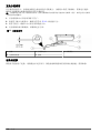
Restore the default settings
The restore option sets all of the program parameters to the default settings.
20
English
A página está carregando...
A página está carregando...
A página está carregando...
A página está carregando...
A página está carregando...
A página está carregando...
A página está carregando...
A página está carregando...
A página está carregando...
A página está carregando...
A página está carregando...
A página está carregando...
A página está carregando...
A página está carregando...
A página está carregando...
A página está carregando...
A página está carregando...
A página está carregando...
A página está carregando...
A página está carregando...
A página está carregando...
A página está carregando...
A página está carregando...
A página está carregando...
A página está carregando...
A página está carregando...
A página está carregando...
A página está carregando...
A página está carregando...
A página está carregando...
A página está carregando...
A página está carregando...
A página está carregando...
A página está carregando...
A página está carregando...
A página está carregando...
A página está carregando...
A página está carregando...
A página está carregando...
A página está carregando...
A página está carregando...
A página está carregando...
A página está carregando...
A página está carregando...
A página está carregando...
A página está carregando...
A página está carregando...
A página está carregando...
A página está carregando...
A página está carregando...
A página está carregando...
A página está carregando...
A página está carregando...
A página está carregando...
A página está carregando...
A página está carregando...
A página está carregando...
A página está carregando...
A página está carregando...
A página está carregando...
A página está carregando...
A página está carregando...
A página está carregando...
A página está carregando...
A página está carregando...
A página está carregando...
A página está carregando...
A página está carregando...
A página está carregando...
A página está carregando...
A página está carregando...
A página está carregando...
A página está carregando...
A página está carregando...
A página está carregando...
A página está carregando...
A página está carregando...
A página está carregando...
A página está carregando...
A página está carregando...
A página está carregando...
A página está carregando...
A página está carregando...
A página está carregando...
A página está carregando...
A página está carregando...
A página está carregando...
A página está carregando...
A página está carregando...
A página está carregando...
A página está carregando...
A página está carregando...
A página está carregando...
A página está carregando...
A página está carregando...
A página está carregando...
A página está carregando...
A página está carregando...
A página está carregando...
A página está carregando...
A página está carregando...
A página está carregando...
A página está carregando...
A página está carregando...
A página está carregando...
A página está carregando...
A página está carregando...
A página está carregando...
A página está carregando...
A página está carregando...
A página está carregando...
A página está carregando...
A página está carregando...
A página está carregando...
A página está carregando...
A página está carregando...
A página está carregando...
A página está carregando...
A página está carregando...
A página está carregando...
A página está carregando...
A página está carregando...
A página está carregando...
A página está carregando...
A página está carregando...
A página está carregando...
A página está carregando...
A página está carregando...
A página está carregando...
A página está carregando...
A página está carregando...
A página está carregando...
A página está carregando...
A página está carregando...
A página está carregando...
A página está carregando...
A página está carregando...
A página está carregando...
A página está carregando...
A página está carregando...
A página está carregando...
A página está carregando...
A página está carregando...
A página está carregando...
A página está carregando...
A página está carregando...
A página está carregando...
A página está carregando...
A página está carregando...
A página está carregando...
A página está carregando...
A página está carregando...
A página está carregando...
A página está carregando...
A página está carregando...
A página está carregando...
A página está carregando...
A página está carregando...
-
 1
1
-
 2
2
-
 3
3
-
 4
4
-
 5
5
-
 6
6
-
 7
7
-
 8
8
-
 9
9
-
 10
10
-
 11
11
-
 12
12
-
 13
13
-
 14
14
-
 15
15
-
 16
16
-
 17
17
-
 18
18
-
 19
19
-
 20
20
-
 21
21
-
 22
22
-
 23
23
-
 24
24
-
 25
25
-
 26
26
-
 27
27
-
 28
28
-
 29
29
-
 30
30
-
 31
31
-
 32
32
-
 33
33
-
 34
34
-
 35
35
-
 36
36
-
 37
37
-
 38
38
-
 39
39
-
 40
40
-
 41
41
-
 42
42
-
 43
43
-
 44
44
-
 45
45
-
 46
46
-
 47
47
-
 48
48
-
 49
49
-
 50
50
-
 51
51
-
 52
52
-
 53
53
-
 54
54
-
 55
55
-
 56
56
-
 57
57
-
 58
58
-
 59
59
-
 60
60
-
 61
61
-
 62
62
-
 63
63
-
 64
64
-
 65
65
-
 66
66
-
 67
67
-
 68
68
-
 69
69
-
 70
70
-
 71
71
-
 72
72
-
 73
73
-
 74
74
-
 75
75
-
 76
76
-
 77
77
-
 78
78
-
 79
79
-
 80
80
-
 81
81
-
 82
82
-
 83
83
-
 84
84
-
 85
85
-
 86
86
-
 87
87
-
 88
88
-
 89
89
-
 90
90
-
 91
91
-
 92
92
-
 93
93
-
 94
94
-
 95
95
-
 96
96
-
 97
97
-
 98
98
-
 99
99
-
 100
100
-
 101
101
-
 102
102
-
 103
103
-
 104
104
-
 105
105
-
 106
106
-
 107
107
-
 108
108
-
 109
109
-
 110
110
-
 111
111
-
 112
112
-
 113
113
-
 114
114
-
 115
115
-
 116
116
-
 117
117
-
 118
118
-
 119
119
-
 120
120
-
 121
121
-
 122
122
-
 123
123
-
 124
124
-
 125
125
-
 126
126
-
 127
127
-
 128
128
-
 129
129
-
 130
130
-
 131
131
-
 132
132
-
 133
133
-
 134
134
-
 135
135
-
 136
136
-
 137
137
-
 138
138
-
 139
139
-
 140
140
-
 141
141
-
 142
142
-
 143
143
-
 144
144
-
 145
145
-
 146
146
-
 147
147
-
 148
148
-
 149
149
-
 150
150
-
 151
151
-
 152
152
-
 153
153
-
 154
154
-
 155
155
-
 156
156
-
 157
157
-
 158
158
-
 159
159
-
 160
160
-
 161
161
-
 162
162
-
 163
163
-
 164
164
-
 165
165
-
 166
166
-
 167
167
-
 168
168
-
 169
169
-
 170
170
-
 171
171
-
 172
172
-
 173
173
-
 174
174
-
 175
175
-
 176
176
-
 177
177
-
 178
178


em outras línguas
- español: Hach SD900
- français: Hach SD900
- English: Hach SD900
- 日本語: Hach SD900
Artigos relacionados
-
 Hach AS950 AWRS Basic Installation And Maintenance
-
 Hach AS950 AWRS Basic Installation And Maintenance
-
 Hach AS950 AWRS Basic Installation And Maintenance
-
 Hach AS950 AWRS Basic Operations
-
 Hach QbD1200 AutoSampler Manual do usuário
-
 Hach HIAC PODS Basic User Manual
-
 Hach BODTrak II Basic User Manual
-
Hach CL17sc Manual do usuário
-
 Hach FL900 Series Basic User Manual
-
 Hach NA5600 sc Na+ Guia de instalação


