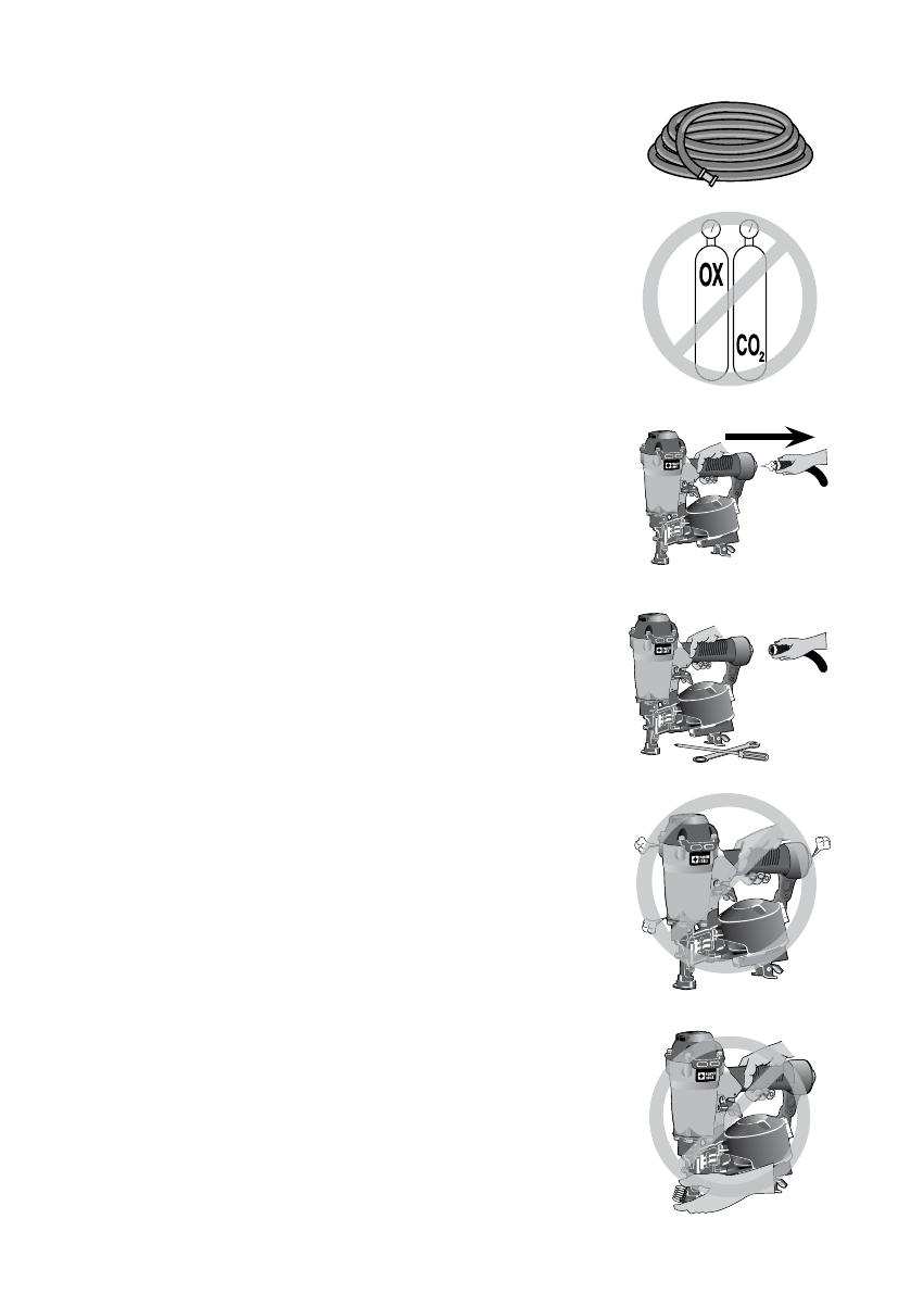
Porter Cable RN175B Manual do usuário

Categoria
Pistola de pregos
Tipo
Manual do usuário

Este manual também é adequado para

1 - ENG
RN175B
ROOFING COIL NAILER
Cloueuse pour toiture à
clous en bobine
Clavadora para techado
a resorte
www.portercable.com
INSTRUCTIVO DE OPERACIÓN, CENTROS
DE SERVICIO Y PÓLIZA DE GARANTÍA.
LÉASE ESTE INSTRUCTIVO
ANTES DE USAR EL PRODUCTO.
Française: Page 17
Español: Página 34
Instruction manual
Manuel d'instructions
Manual de'instrucciones
9R195654RA
2 - ENG
        
       

    These safety glasses must
conform to ANSI Z87.1 requirements (approved glases
have “Z87” printed or stamped on them). It is the
employer’s responsibility to enforce the use of eye
protection equipment by the tool operator and other
people in the work area. (Fig. A)
        

 
      

(Fig. A)
 

(Fig. B)
       
        [Not to
exceed 120 psi (8.3 bar).] Do not connect the tool to a
compressor rated at over 175 psi. The tool operating
pressure must never exceed 175 psi even in the event of
regulator failure. (Fig. C)
           
         

(Fig. D)
70 psi
4.9 bar






save these instructions
When using any pneumatic tool, all safety precautions, as outlined
below, should be followed to avoid the risk of death or serious injury. Read and
understand all instructions before operating the tool.

The definitions below describe the level of severity for each signal word. Please read the
manual and pay attention to these symbols.
Indicates an imminently hazardous situation which, if not avoided, 
result in .
Indicates a potentially hazardous situation which, if not avoided,
 result in 
Indicates a potentially haz ard ous situation which, if not avoided, 
result in 
Used without the safety alert symbol indicates a situation which, if not
avoided, result in
3 - ENG
          
      
    
     Never use combustible
gases or any other reactive gas as a power source for this
tool. Danger of explosion and/or serious personal injury
may result. (Fig. E)
  
       
        
(Fig. F)
         
       
       
        

     
        

       
 If the contact trip is adjusted when the tool
is connected to the air supply and nails are loaded,
accidental discharge may occur. (Fig. G)
•        

      
         Do
not load fasteners with the trigger or the contact trip
depressed to prevent unintentional driving.
 
       
           
Do not remove spring from contact trip. Make
daily inspections for free movement of trigger and contact
trip. Uncontrolled discharge could result.
•          
         
     
 Leaking air, damaged parts or missing parts
should be repaired or replaced before use. Refer to
Repairs. (Fig. H)
 (Fig.I)
 
 
   Work safe! Respect the tool as a
working implement. (Fig. J)
•       

When tool is not in use, it should be locked
in a safe place, out of the reach of children.
 






4 - ENG
         
     
Accidental discharge could result.
 
Loss of balance may cause personal injury.
(Fig. K)
         


 


Do not use the body of the tool or top cap
as a hammer. Discharged fasteners may follow unex-
pected path and cause injury. (Fig. L)
         
M)
    Maintenance  Repairs  


          
          


         
       
   Be aware that the nail may
follow the grain of the wood (shiner), causing it to protrude
unexpectedly from the side of the work material. Drive the
nail perpendicular to the grain to reduce risk of injury. (Fig. N)
      

      
(Fig. O)
 

          
        
        
        
         
(Fig. P)
 

      Be sure
the workpiece is properly secured before pressing the
nailer against the material.The contact trip may cause the
work material to shift unexpectedly. (Fig. Q)
          
         





5 - ENG
      Driving a nail into
another nail may also cause a spark. (Fig. R)
 

        
(Fig. S)
        
    

        
      

 


 

       

(Fig. T)

• Do not engage the tool against the work surface
with a strong force.
• Allowthetooltorecoilfullyaftereachactuation.
• Usesequentialactiontrigger.
 




        
        

 


• Disconnectairsupply.
• Engagetriggerlock
• Avoidcontactwithtriggerduringadjustments.
          


(Fig. U)
 


A moment of inattention while operating power tools may
result in serious personal injury.






6 - ENG
Use of this product may expose you to chemicals known to the State
of California to cause cancer, birth defects and other reproductive harm. 

         
       
 Allowing dust
to get into your mouth, eyes, or lay on the skin may promote absorption of
harmful chemicals.
Use of this tool can generate and/or disburse dust, which may cause
serious and permanent respiratory or other injury. Always use NIOSH/OSHA approved
respiratory protection appropriate for the dust exposure. Direct particles away from
face and body. Always operate tool in well-ventilated area and provide for proper dust
removal. Use dust collection system wherever possible.
ALWAYS USE SAFETY GLASSES. Everyday eyeglasses are NOT safety
glasses. Also use face or dust mask if operation is dusty. ALWAYS WEAR CERTIFIED
SAFETY EQUIPMENT:
• ANSIZ87.1eyeprotection(CAN/CSAZ94.3),
• ANSIS12.6(S3.19)hearingprotection,
• NIOSH/OSHArespiratoryprotection.
          
ImportantSafetyInstructions
save these instructions


 0.120" (3mm) diameter, 15º wire collated roofing nails
 3/4"(19mm)-1-3/4"(44.5mm)
 1/4" NPT (6.4 mm)

7 - ENG


A. Exhaust deflector
B. Selectable trigger
C. Air Inlet with quick
connect coupler
D. Canister
E. Door latch
F. Safety contact tip
G. Depth adjustment wheel
H. Door
I. Tool-Free Shingle Guide
J. Trigger lock button
k. Mode selector button

         
         


Keep fingers AWAY from the trigger when not driving fasteners to avoid
accidental actuation. Never carry a tool with finger on the trigger. In bump action mode
(contact actuation mode), the tool will drive a fastener if the contact trip is bumped
while the trigger is depressed.
The RN175B is equipped with a selectable trigger. This trigger allows the operator to
select either single sequential action trigger mode or bump action trigger mode. In
accordance with the ANSI Standard SNT-101-2002, the trigger is assembled in the
single sequential action trigger mode. To change the trigger mode, see 
instructions in the Operation section of the manual. The selectable trigger also has a
trigger lock button to keep the trigger locked at all times when the tool is not in use.

The tool is equipped with a 1/4" (6.4 mm) male quick connector coupling. A 3/8"
(9.5mm)malequickconnectorcouplingisavailablefromPORTER-CABLEandmaybe
used when a 1/4" (6.4 mm) supply line is not available.
 A 3/8" (9.5 mm) supply line (and fittings) are required for maximum tool
performance.
Always use couplings that relieve all pressure from the tool when it is
disconnected from the power supply. Always use hose connectors that shut off air
supply from compressor when the tool is disconnected.
A
F
K
I
8 - ENG

1. Wrap the male end of the fitting with thread seal tape prior to assembly to eliminate
air leaks.
2. To install a 1/4" (6.4 mm) fitting: screw it directly into the air inlet and tighten firmly.
 If an adapter is in the air inlet, remove it prior to inserting the fitting.
3. Toinstalla3/8"(9.5mm)fitting:screwthefittingintothe3/8"(9.5mm)adapterand
then into the air inlet of the tool and tighten firmly.


Read the section titled
 at the beginning of this manual. Always wear eye and ear protection when
operating this tool. Keep the nailer pointed away from yourself and others. For safe
operation, complete the following procedures and checks before each use of the nailer.
To reduce the risk of damage to the tool, only use PORTER-CABLE
pneumatic tool oil or a non-detergent SAE 20 weight oil. Oil with additives or detergent
will damage tool parts.
1. Before you use the nailer, be sure that the compressor tanks have been properly
drained.
2. Lubricate tool:
a. Use PORTER-CABLE pneumatic tool oil or a non-detergent S.A.E. 20 weight
oil. DO NOT use detergent oil or additives as they will damage O-rings and
rubber parts.
b. Use a filter when possible.
c. Add 5 to 7 drops of oil in the air fitting a least twice a day.
3. Wear eye and ear protection.
4. Ensure canister is empty of all fasteners.
5. Check for smooth and proper operation of contact trip. Do not use tool if assembly
is not functioning properly.  tamper with the contact trip.  use a tool
that has the contact trip restrained in the actuated position.
6. Check air supply: Ensure air pressure does not exceed recommended operating
limits;70to120psi,(4.9to8.3bar,5to8.5kg/cm
2
).
7. Keep tool pointed away from yourself and others.
8. Connect air hose.
9. Checkforaudibleleaksaroundvalvesandgaskets.Neveruseatoolthatleaksor
has damaged parts.
          
         



Keep the tool pointed away from yourself and others. Serious personal
injury may result.
Never load nails with the contact trip or trigger activated. Personal
injury may result.
9-ENG
1. Read all   before
using tool.
2. Connect the air supply to the tool.
3. Lift the canister door latch (E) to open
the nail guide door (H).
4. Rotate the canister door (I) open.
5. Adjust the nail platform (J) to properly
accommodate the nail length being
used. Pull the nail platform (J) up or
down for desired nail.
 
lowest position 1-1/2" (38 mm) - 1 3/4" (44.5mm)
center position 1-1/4" (32 mm)
upper position 3/4"(19mm)-1"(25mm)
3/4"(19mm)nailsarenotavailableforthistool.
6. Place the coil on the nail platform (J).Observe fastener icon (K) Fig. 4. Insert
fasteners (L) with points down.  Fasteners must point in the same
direction as they will be driven.
7. Uncoil enough nails [approximately 3" (76 mm)] to reach the nose of the tool.
8. Insert the first nail into the nose and the second nail (M) between the two rails of
the feed pawl as shown in Fig. 5.
 Be careful not to deform the coil of nails during the loading process. Otherwise,
the nail guide door will not close and the nails might not feed consistently.
9. Closethecanisterdoor(I)completely.
10. Close the nail guide door (H) making sure the door latch (E) is completely engaged
as shown in Fig. 6.

K




I
10 - ENG

To reduce the risk of injury,  wear proper eye ANSI Z87.1
(CAN/CSAZ94.3)andhearingprotectionANSIS12.6(S3.19)whenoperatingthistool.
The tool can be actuated using one of two modes: single sequential actuation trigger
mode and contact actuation trigger mode.


Allow the tool to recoil off the work
surface after actuation. If the contact trip remains
depressed a nail will be driven each time the trigger is
released and pulled, which could result in accidental
actuation, possibly causing injury.
The sequential actuation trigger’s intended use is
for intermittent fastening where accurate fastener
placement is desired.


1. Depress the contact trip firmly against the work surface.
2. Pull the trigger.
3. Allow the tool to recoil from the work surface.


The contact actuation trigger is intended for rapid
fastening on flat, stationary surfaces.
Using the contact actuation trigger, two methods are
available: 


1. Depress the contact trip against the work surface.
2. Pull the trigger to drive the fastener.
3. Allow the tool to recoil off the work surface

1. Pull the trigger.
2. Depress the contact trip against the work surface. As long as the trigger is pulled,
the tool will drive a fastener every time the contact trip is depressed. This allows
the user to rapidly drive multiple fastener in sequence.

1. Push the (red) trigger lock button down
2. Rotate the (black) selectable trigger button counterclockwise
3. Align the triangular indicator to the desired mode
• ForSequentialMode
• ForContactMode
4. Then push the trigger lock button back up to the un-locked position.

To reduce risk of serious injury from accidental actuation when
attempting to adjust depth, ALWAYS:







11 - ENG
• Disconnect air supply and engage trigger
lock.
Avoid contact with trigger during
adjustments.
The depth that the fastener is driven can be adjusted
using the depth adjustment next to the trigger of
the tool.
The depth of drive is factory adjusted to
a nominal setting. Test fire a fastener and check
depth. If a change is desired:
1. To drive the nail shallower, rotate the depth
setting wheel (G) to the right.
2. To drive a nail deeper, rotate the depth setting wheel (G) to the left.
The adjustment knob has detents every 1/4 turn. Test drive another fastener and check
depth. Repeat as necessary to achieve desired results. The amount of air pressure
required will vary depending on the size of the fastener and the material being
fastened. Experiment with the air pressure setting to determine the lowest setting that
will consistently perform the job at hand. Air pressure in excess of that required can
cause premature wear and/or damage to the tool.

Adjust directional exhaust deflector (A) Fig. 10, so
that the exhaust air blast will be directed away from
the operator. The exhaust deflector can be adjusted
any position for directing the exhaust blast away from
the operator. Grasp the deflector and rotate it to the
desired position for the current application. 
Non-skid pads (N) help keep the tool from sliding off
the roof.

Adjust shingle guide (O):
1. Loosen the adjusting lever (P) and slide the locking plate to desired position.
2. Tighten adjusting lever firmly.
The locking plate (O) can be used as an aid to position the shingle being nailed a
specific distance (Q) from the front edge of the previous row of shingles (R) as shown.

         
         



A

O

O
12 - ENG
If a nail becomes jammed in the nosepiece, keep
the tool pointed away from you and follow these
instructions to clear:
1. Disconnect the air supply from the tool.
2. Lift the canister door latch (E) to open the nail
guide door (H).
3. Open the canister door.
4. Remove the jammed nail.
5. Correct any deformation that may have occurred
to the nail coil.
 Should nails continue to jam frequently in nosepiece, have tool serviced by an
authorized PORTER-CABLE service center.

When operating tools at temperatures below freezing:
1. Make sure compressor tanks have been properly drained prior to use.
2. Keep tool as warm as possible prior to use.
3. Make certain all fasteners have been removed from canister.
4. Put 5 to 7 drops of PORTER-CABLE pneumatic tool oil in the air inlet.
5. Lower air pressure to 80 psi (5.5 bar) or less.
6. Reconnect air and load nails into canister.
7. Actuate the tool 5 or 6 times into scrap lumber to lubricate O-rings.
8. Turn pressure up to operating level (not to exceed 120 psi) and use tool as normal.
9. Re-lubricateatleastoncedaily.
10. Always drain the compressor tanks at least once a day.

Tool should operate normally. However, keep tool out of direct sunlight as excessive
heat can deteriorate bumpers, O-rings and other rubber parts resulting in increased
maintenance.

         
         


  
Lubricate tool with 5-7
drops of PORTER-CABLE
Pneumatic Tool Oil
Prevents failure
of o-rings
Insert drops into air fitting
on end cap of tool
Drain compressor tanks
and hoses daily
Prevents accumulation
of moisture in
compressor and nailer
Open petcocks or other
drain valves on compressor
tanks. Allow any accumulated
water to drain from hoses

13 - ENG
  
Clean canister, feed
piston area and contact
trip mechanism.
Permits smooth
operation of magazine,
reduces wear and
prevents jams.
Blow clean with compressor
air. The use of oils, lubricants
periodically or solvents is
not recommended as they
tend to attract debris.
Before each use, check
to insure all screws,
nuts and fasteners are
tight and undamaged.
Prevents jams, leaks
and premature failure
of tool parts.
Tighten loose screws or other
fasteners using the appropriate
hex wrench or screwdriver.

Never use solvents or other harsh chemicals for cleaning the non-metal-
lic parts of the tool. These chemicals may weaken the materials used in these parts. Use
a cloth dampened only with water and mild soap. Never let any liquid get inside the tool;
never immerse any part of the tool into a liquid.

For assistance with your tool, visit our website at www.portercable.com for a list of
service centers, or call the PORTER-CABLE Customer Care Center at 1-888-848-5175
(U.S. & Canada Only).


Use only identical replacement parts. For a parts list or to order parts, visit our service
website at http://servicenet.deltaportercable.com/. You can also order parts from
your nearest PORTER-CABLE Factory Service Center or PORTER-CABLE Authorized
Warranty Service Center. Or, you can call our Customer Care Center at 1-888-848-5175
(U.S. & Canada Only).

All quality tools will eventually require servicing and/or replacement of parts. For
information about PORTER-CABLE, its factory service centers or authorized warranty
service centers, visit our website at www.portercable.com or call our Customer Care
Center at 1-888-848-5175 (U.S. & Canada Only). All repairs made by our service centers
are fully guaranteed against defective material and workmanship. We cannot guarantee
repairs made or attempted by others.
You can also write to us for information at PORTER-CABLE, 4825 Highway 45 North,
Jackson, Tennessee 38305 - Attention: Product Service. Be sure to include all of the
information shown on the nameplate of your tool (model number, type, serial number, etc.).

Since accessories, other than those offered by PORTER-CABLE, have not
been tested with this product, use of such accessories with this tool could be hazardous.
To reduce the risk of injury, only PORTER-CABLE recommended accessories should be
used with this product.
14 - ENG
A complete line of accessories is available from your PORTER-CABLE Factory Service
Center or a PORTER-CABLE Authorized Warranty Service Center. Please visit our Web Site
www.portercable.com for a catalog or for the name of your nearest supplier.

 will repair, without charge, any defects due to faulty materials or
workmanship for three years from the date of purchase. This warranty does not cover
part failure due to normal wear or tool abuse. For further detail of warranty coverage and
warranty repair information, visit www.portercable.com or call 1-888-848-5175 (U.S. &
Canada Only). This warranty does not apply to accessories or damage caused where
repairs have been made or attempted by others. This warranty gives you specific legal
rights and you may have other rights which vary in certain states or provinces.
In addition to the warranty, PORTER-CABLE tools are covered by our:
PORTER-CABLE will maintain the tool and replace worn parts
caused by normal use, for free, any time during the first year after purchase.
     If you are not completely satisfied with the
performance of your PORTER-CABLE Power Tool, Laser, or Nailer for any reason, you
canreturnitwithin90daysfromthedateofpurchasewithareceiptforafullrefund–no
questions asked.
This warranty does not apply to products sold in Latin America. For
products sold in Latin America, see country specific warranty information contained in
the packaging, call the local company or see website for warranty information.
To register your tool for warranty service visit our website at www.portercable.com.

If your warning labels become illegible or are missing, call 1-888-848-5175 (U.S. &
Canada Only) for a free replacement.
15 - ENG

MANY COMMON PROBLEMS CAN BE SOLVED EASILY BY UTILIZING THE CHART
BELOW. FOR MORE SERIOUS OR PERSISTENT PROBLEMS, CONTACT A PORTER-
CABLE SERVICE CENTER OR CALL 1 888 848-5175.


  
Air leak near top of
tool or in trigger area
Loose screws. Tighten screws.
Worn or damaged
o-rings or seals.
Install Overhaul Kit.
Tool does nothing or
operates sluggishly
Inadequate air supply. Verify adequate air supply.
Inadequate lubrication. Put 5 or 7 drops of
oil into air inlet.
Worn or damaged
o-rings or seals.
Install Overhaul Kit.
Air leak near
bottom of tool
Loose screws. Tighten screws.
Worn or damaged
o-rings or bumper.
Install Overhaul Kit.
Tool jams frequently Incorrect fasteners. Verify approved fasteners
of correct size and 15°
collation angle.
Damaged fasteners.
Bent collation wire.
Replace with undamaged
fasteners.
Canister or nose screws loose Tighten screws.
Canister is dirty. Clean magazine.
Driver tip is worn or damaged. Install Driver Maintenance Kit.
Other Contact a PORTER-CABLE
Authorized Warranty
Service Center


 (inch/mm) 10.63/ 270
 (inch/mm) 4.33/ 110
 (inch/mm) 10.24/ 260
 (lbs/kg) 4.78/ 2.17
 70-120 psi (4.8 to 8.3 bar)

4.13 CFM
 120 nails
16 - ENG



          

NR

Portable
Handcarry

5.5 HP Gas
2 HP Elec.

8 HP Gas

Industrial


NR
NR
NR NR
NR NR

NR NR
17 - FR


conservez ces directives
lorsqu’on utilise un outil pneumatique quelconque, respecter toutes les
mesures de sécurité, décrites ci-après, pour éviter un risque de décès ou de blessures graves.
Lire et assimiler toutes les directives avant d’utiliser l’outil.

Les définitions ci-dessous décrivent le niveau de gravité pour chaque symbole. Veuillez lire le
mode d’emploi et porter une attention particulière à ces symboles.
indique une situation dangereuse imminente qui, si elle n’est pas évitée,

indique une situation potentiellement dangereuse qui, si elle n’est
pas évitée,

se solder par un

.
indique une situation potentiellement dangereuse qui, si elle n’est pas
évitée

se solder par

.
Si l'outil est utilisé sans respecter le symbole d'avertissement, cela  de causer
.
        
       
      
      
        
Ces lunettes
de sécurité doivent être conformes à la norme ANSI Z87.1
(les lunettes approuvées portent l’inscription imprimée
ou estampillée « Z87 »). L’employeur a la responsabilité
d’imposer le port d’un équipement de protection oculaire
par l’opérateur de l’outil et toute personne se trouvant
dans la zone immédiate de travail. (fig. A)
 
        

       
      
       
       
(fig. A)
       

(fig. B)
 

Ne pas raccorder l’outil à un compresseur d’une puissance nominale supérieure
à 12,6 bars (175 psi). La pression de fonctionnement de l’outil ne doit jamais
excéder 12,6 bars (175 psi) même dans l’éventualité d’une défaillance du
régulateur. (fig. C)
70 psi
4.9 bar



18 - FR
 


(fig. D)
 
       

        
Ne jamais utiliser
de gaz combustibles ou tout autre type de gaz réactif
comme source d’énergie pour cet outil. Leur utilisation
représente un danger d’explosion et peut se solder par
des blessures corporelles graves. (fig. E)
 


(fig. F)
    



 
      
       
       
      
       
     Un déclenchement
intempestif pourrait se produire lors du réglage du
déclencheur si l’outil est raccordé à la source d’alimentation
en air en présence de clous dans le chargeur. (fig. G)
• 
        
     

     
Ne pas charger les attaches alors que la gâchette
est enfoncée ou que le déclencheur de contact est activé
pour éviter un enfoncement accidentel.
     
        
        

     Ne pas retirer le
ressort du déclencheur. Inspecter quotidiennement le bon
fonctionnement de la détente et du déclencheur. Une
décharge non contrôlée pourrait survenir.
• 


      Les






19-FR
fuites d’air ainsi que les pièces endommagées ou
manquantes devraient être réparées ou remplacées avant
utilisation. Se reporter à la rubrique Réparations. (fig. H)
 I)
 
         
    Travailler en toute
sécurité! Traiter l’outil comme un instrument essentiel de
travail. (fig. J)
         
      
       Verrouiller
l’outil dans un endroit sûr, hors de la portée des enfants
lorsqu’il n’est pas utilisé.
 

 
       
    Un tir accidentel peut se
produire.
 
Une perte d’équilibre risque d’entraîner
une blessure corporelle. (fig. K)
        
     

       



     Ne pas utiliser
le corps de l’outil ou son couvercle supérieur comme
marteau. Les attaches éjectées peuvent suivre une
trajectoire inattendue et provoquer des blessures. (fig. L)
       
    
M)
      Entretien  Réparations
      

        



 

Il est possible
que le clou suive le fil du bois et sorte inopinément sur





20 - FR
le côté de la pièce. Enfoncer le clou perpendiculairement
au fil du bois pour réduire le risque de blessures. (fig. N)
         
         
     

(fig. O)
       


         


       
  

(fig. P)
 

         
S’assurer que la pièce
est bien fixe avant d’appuyer la cloueuse contre celle-ci.
La force du déclencheur peut entraîner le déplacement
inopiné de la pièce. (fig. Q)
        
      

    Une étincelle pourrait
également être produite si un clou est enfoncé sur un
autre clou. (fig. R)
           


       
(fig. S)
        
       
      
      
      



        
      

       

 





  • Page 1 1
  • Page 2 2
  • Page 3 3
  • Page 4 4
  • Page 5 5
  • Page 6 6
  • Page 7 7
  • Page 8 8
  • Page 9 9
  • Page 10 10
  • Page 11 11
  • Page 12 12
  • Page 13 13
  • Page 14 14
  • Page 15 15
  • Page 16 16
  • Page 17 17
  • Page 18 18
  • Page 19 19
  • Page 20 20
  • Page 21 21
  • Page 22 22
  • Page 23 23
  • Page 24 24
  • Page 25 25
  • Page 26 26
  • Page 27 27
  • Page 28 28
  • Page 29 29
  • Page 30 30
  • Page 31 31
  • Page 32 32
  • Page 33 33
  • Page 34 34
  • Page 35 35
  • Page 36 36
  • Page 37 37
  • Page 38 38
  • Page 39 39
  • Page 40 40
  • Page 41 41
  • Page 42 42
  • Page 43 43
  • Page 44 44
  • Page 45 45
  • Page 46 46
  • Page 47 47
  • Page 48 48
  • Page 49 49
  • Page 50 50
  • Page 51 51
  • Page 52 52

Porter Cable RN175B Manual do usuário

Categoria
Pistola de pregos
Tipo
Manual do usuário
Este manual também é adequado para