Toto TLP01701U Installation and Owner's Manual
- Categoria
- Louças sanitárias
- Tipo
- Installation and Owner's Manual
Este manual também é adequado para

TOTO U.S.A., Inc. 1155 Southern Road,
Morrow, Georgia 30260
Tel: 888-295-8134 Fax: 800-699-4889
www.totousa.com
0GU4270
Rev A
Warranty Registration and Inquiry
For product warranty registration, TOTO U.S.A. Inc. recommends online warranty registration. Please visit
our web site http://www.totousa.com. If you have questions regarding warranty policy or coverage, please con-
tact TOTO U.S.A. Inc., Customer Service Department, 1155 Southern Road, Morrow, GA 30260
(888) 295-8134 or (678) 466-1300 when calling from outside of U.S.A.
Installation and Owner’s Manual
Manual de instalación y del propietario
Manuel d’installation et d’utilisation
Manual de Instalação e do Proprietário
ZN Autofaucet
ZN Grifo Automático
ZN Robinet Automatique
ZN Torneira Automática
TLP01701U
TLP01702U

2
ENGLISH
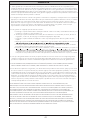
THANK YOU FOR CHOOSING TOTO!
The mission of TOTO is to provide the world with healthy, hygienic and more
comfortable lifestyles. We design every product with the balance of form and
function as a guiding principle. Congratulations on your choice.
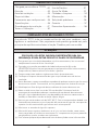
How to Use.........................................9
Mode Adjustment..............................9
Care and Cleaning............................11
Maintenance......................................12
Troubleshooting................................14
Warranty.............................................15
Rough-In Dimensions........................58
Thanks for Choosing TOTO!...............2
Warnings...............................................2
Before Installation................................3
Included Parts.......................................4
Tools You Will Need.............................4
Specifications........................................4
Installation Procedure..........................5
Testing and Calibration........................8
TABLE OF CONTENTS
PLEASE READ THESE IMPORTANT SAFEGUARDS FOR YOUR PERSONAL
SAFETY AND TO PREVENT DAMAGE TO PRODUCT AND PROPERTY.
⚠ To ensure the product installation is completed correctly, please carefully read
this manual entirely before beginning installation.
⚠ Comply with all instructions proceeded by the caution symbol (⚠) or notice
label (NOTICE) to avoid potential dangers such as injury or death, electrical
shock, property damage, or invalidation of warranty.
⚠ Comply with all local plumbing codes.
⚠ Make sure the water supply is shut off before beginning installation.
⚠ Never disassemble, repair or modify the product in any way not described by
this manual. Refer the product to a service engineer, if needed.
⚠ Do not block the flow of water at the spout opening during use.
⚠ Mount the outlet in a location higher than 100 mm from the floor. Select the
outlet mounting location so that condensation on the water supply pipe and
water splashed during use of the product does not contact the outlet, or
consider using a water-proof outlet.
⚠ Do not use supplied water hotter than 185ºF (85ºC). In order to prevent
scalding due to improper operation, set the cold water supply pressure to
higher than the hot water supply pressure or to the same pressure.
⚠ Do not reverse hot and cold inlets.
⚠ Do not install in the following environments: outdoors, in humid locations such
as saunas, freezing locations, or moving vehicles. If the temperature drops to
freezing, wrap the pipes with insulation.
⚠ Avoid placing any objects within the detection range of the infrared sensor.
WARNINGS

3
ENGLISH
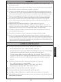
WARNINGS
⚠ Always close the water shutoff valve before cleaning the filter and wait for the
filter on the hot water side to cool down.
⚠ Do not clean the product with cleaning agents other than diluted neutral
detergent.
⚠ Handle the product with care. Do not subject the product to strong forces,
drops, or impacts.
⚠ Only connect the controller to a GFCI protected outlet that is connected to a
surge protector rated no more than 15A. Do not use damaged or loose outlet.
⚠ Do not use this product with any power supply other than specified (AC 100-
240 VAC, 50/60 Hz). The voltage supply must be separately switchable.
⚠ Do not damage, modify (cut or extend), bend forcibly, twist, pull, pinch, roll up,
heat or put heavy objects on the power cord or power plug.
⚠ Always unplug by holding the plug by the base. When inserting, push it in all
the way to the base. Do not wet the power plug or electrical parts or insert or
pull power plug with wet hands. Always make sure the power plug is clean of
dust or dirt. Avoid operation during thunderstorms.
⚠ Make sure the power cord does not come in contact with the hot water supply
pipe.
⚠ Unplug the product if it will not be used for a long period of time.
⚠ Perform regular maintenance. Do not leave abnormalities, such as rattling
parts, unaddressed. At least annually, check around pipes for water leakage,
replace worn check valves, and turn the temperature control handle of the
thermal mixing valve to prevent buildup or sticking.
BEFORE INSTALLATION
Check the cold and hot water supply pressure.
The working pressure range is 15 psi - 80psi (100 kPa - 551 kPa).
Make sure to set the cold water supply pressure to higher than the hot water
supply pressure, or to the same pressure.
When the water supply pressure is higher than 80 psi (551kPa), be sure to
reduce the pressure within a range of 20 to 80 psi by using a pressure-reducing
valve (sold separately).
Check the temperature of the hot and cold water supplies.
The recommended temperature range:
HOT supply: 120ºF-180ºF (49ºC-82ºC)
COLD supply: 39ºF-80ºF (4ºC-27ºC)
Flush all water lines prior to installation .
Turn off the water supply at the supply stop.
Make sure to not damage the sensor surface during installation.
Do not place other devices that use an inverter or infrared sensor near the faucet.

4
ENGLISH
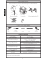
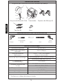
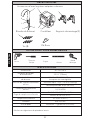
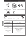
Spout assembly
Screws (8)
Key
Controller Mounting brackets (2)
Check to make sure you have the following parts indicated below:
INCLUDED PARTS
TOOLS YOU WILL NEED
Drill
Phillips
Screwdriver
Pencil
Level
Tape
Measure
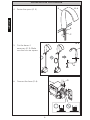
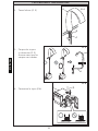
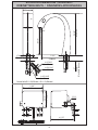
SPECIFICATIONS
A F
H
G
I
B
C
D
J
E
Power supply AC 100~240 V
Power Cord Length 29-1/2” (750mm)
Sensor Detection Range
5-1/8’”~ 7-7/8” (130~200mm)
Sensor is self-adjusting.
Water Supply Pressure
Minimum required: 15 psi (138 kPa) (Flowing)
Maximum allowed: 80 psi (551 kPa)
Water Supply Connection 1/2-14 NSPM
Inlet Temperature range
HOT: 120~180°F (49~82°C)*
COLD: 39~80°F (4~27°C)
Ambient Temperature 32~104°F (0~40°C)
Humidity Max. 90% RH
Flow Rate Maximum 1.1 gallon/min (4.2 L/min)
*Check your local plumbing codes.

5
ENGLISH
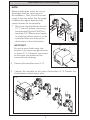
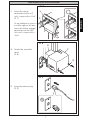
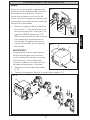
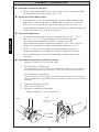
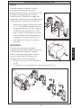
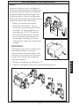
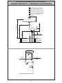
NOTE:
Before installing the faucet, be sure to
thoroughly flush the supply pipes of
dirt and debris. Then, shut off the water
supply at the stop valves. See the rough-
in dimension page to determine the
correct location for the controller.
1. Mount the inlet brackets on the wall
(ill. 1). Use wall anchors if necessary
(not provided). Brackets MUST be
mounted 3-¾” (95mm) apart (center
to center) to connect correctly to the
controller. Make sure there are no
obstructions to the inlet brackets.
IMPORTANT!
Be sure to mount each water inlet
bracket in the correct upright direction
as shown (ill. 1). Otherwise, the strainer
on the water inlet bracket will be
inaccessible for cleaning.
INSTALLATION PROCEDURE
F
G
H
I
H
I
J
J
I
95mm
2. Remove the controller cover (ill. 2).
3. Connect the controller to the water inlet brackets (ill. 3) Connect the
flexible hoses to the bracket inlets.
ill. 1
ill. 2
ill. 3
I

6
ENGLISH
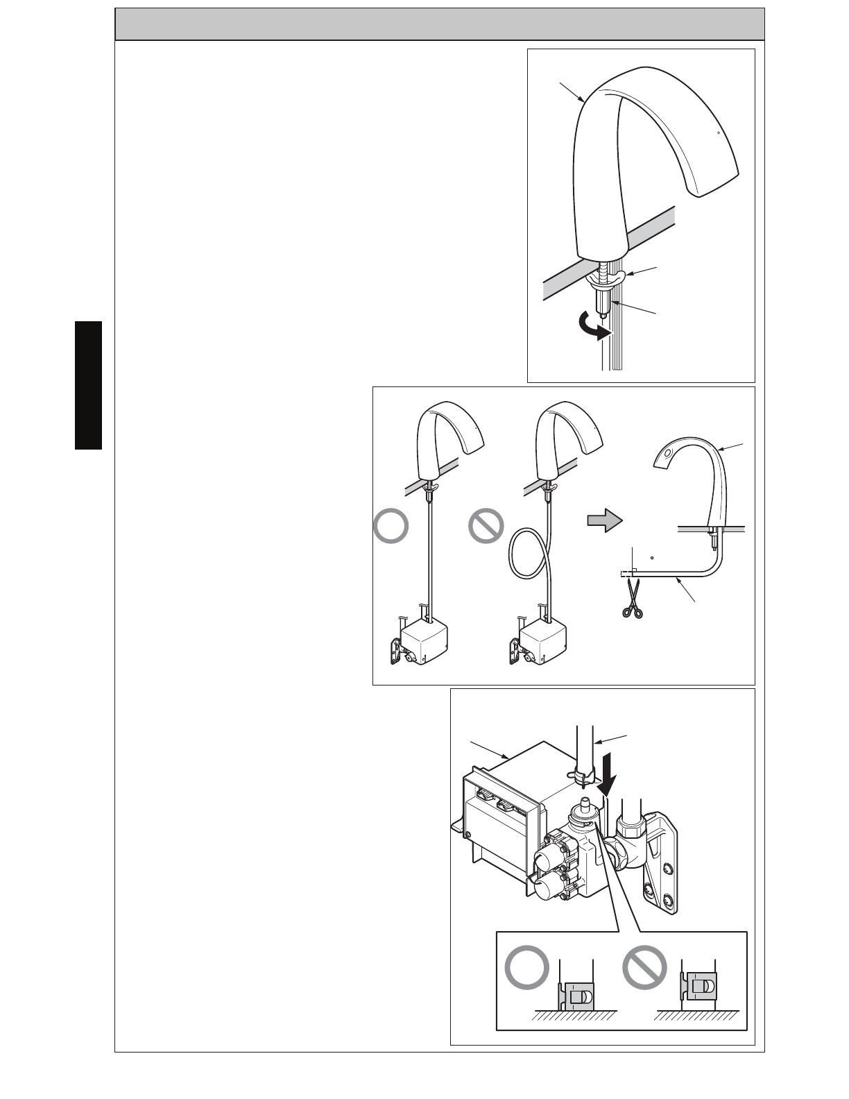
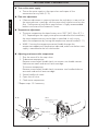
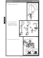
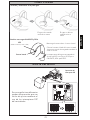
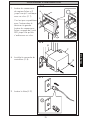
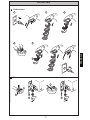
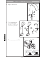
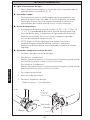
4. Fasten the spout (ill. 4).
5. Cut the hoses if
necessary (ill. 5). Make
sure the cuts are square.
6. Connect the hose (ill. 6).
INSTALLATION PROCEDURE
A
B
C
ill. 4
90
A
D
ill. 5
H
D
ill. 6

7
ENGLISH
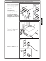
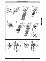
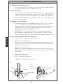
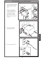
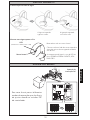
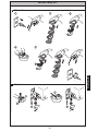
7. Insert the sensor
connectors (white x 2)
until it stops with a ‘click’
(ill. 7).
It’s no problem to insert it
in either right or left one.
Insert the (white, orange)
connectors of the LED
Unit until it stops with a
‘click’.
8. Attach the controller
cover
(ill. 8).
9. Insert the power plug
(ill. 9).
INSTALLATION PROCEDURE
7
E
H
ill. 7
F
G
H
ill. 8
ill. 9

8
ENGLISH
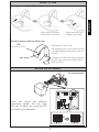
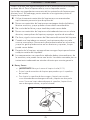
Turn on the water supply
Turn on the water supply at the stop valves and inspect all the
connections for any leaks (Ill. 10).
Flow rate adjustment
If flowrate adjustment is necessary because the wash basin is too small or
the water pressure is too high, turn the stop valve(s) clockwise to limit the
flow. Confirmation of wash basin specifications is highly recommended
before installation of the Automatic Faucet.
Temperature adjustment
The water temperature has been factory set at 100°F (38°C, Max: 42°C ±
3°C). Depending on the supply water pressure and other local conditions,
the water temperature may not be kept as specified. In such a case,
adjust the temperature by turning the temperature control handle (Ill. 11).
NOTE: If turning the temperature control handle changes the
temperature opposite of the direction indicated, make sure the hot water
supply is connected to the left inlet bracket.
Adjusting maximum outlet temperature
1. Shut the water off at the stop valves.
2. To decrease temperature:
Remove screw and pull handle slowly to remove. turn handle counter-
clockwise one notch and reinstall onto cartridge.
To increase temperature:
Remove screw and pull handle slowly to remove. turn handle clockwise
one notch and reinstall onto cartridge.
3. Secure handle with screw.
4. Open shut off valve.
5. Check water temperature.
**Repeat steps 1-5 if necessary.
TESTING AND CALIBRATION
Open
Close
Stop Valve
Hot
Cold
Temperature
Control
Handle
Ill. 11
Temperature Control
Handle
HOT
COLD
Open
Close
Stop valve
Ill. 10
Screw

9
ENGLISH
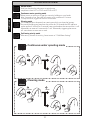
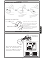
HOW TO USE
MODE ADJUSTMENT
Your new faucet has different
operation modes that are easy
for you to adjust by using the DIP
switches of the controller.
Water comes out when
you hold out your hand.
Hold hand over side sensor.
Temperature of the water will correspond to
the LED color on the spout. RED for HOT,
BLUE for COLD.
Placing hand next to sensor when the water
is not discharging will change the color on
the LED.
Switching between HOT and COLD water.
Starting and stopping the flow of water.
LED
(RED/HOT, BLUE/COLD)
Side Sensor
Water stops when you
withdraw your hand.
DIP switch operation

10
ENGLISH
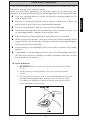
MODE ADJUSTMENT
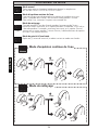
Hold your hand on the side sensor to switch water
temperature from HOT to COLD and COLD to HOT.
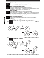
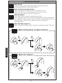
Continuous water spouting mode
Water comes out when you trigger the sensor by holding out your hands.
After 3 seconds of use, the water will remain on for a duration of 1 minute.
To stop the water, trigger the sensor a second time.
Cold water priority mode
After one (1) minute of inactivity, faucet resets to “Cold Water Setting”.
.
Equipment protection wash
When the product is not used for 24 hrs, water will come out automatically
for 5 seconds to protect the lifespan of the automatic faucet.
Cleaning mode
This mode prevents the water from coming out while you clean the lavatory.
Activate by holding your hand over the sensor for 10 seconds the LED indicator
on the spout will turn off for 5 seconds, keep your hand on the sensor while it is off.
Afterwards, no water will come out for 1 min. Afterwards, triggering the sensor
will cause water to come out as usual.
Normal mode
2
3sec 60sec
10-15sec 60sec
Mode ajustment
GB
Ajustement du mode
FR
Modo de ajuste
ES
Ajuste do modo
PT
Continuous water spouting mode
Cleaning mode
-6-

11
ENGLISH
Clean the parts regularly to prevent the accumulation of dirt and lime-scale.
For daily cleaning, use a neutral cleaner.
Acids are necessary ingredients of cleaning materials for removing lime.
However, please pay attention to the following points when cleaning fittings:
Only use cleaning materials which are explicitly recommended for this
type of application.
Never use cleaning materials which contain hydrochloric, formic or
acetic acid, as they may cause considerable damage.
Do not use phosphoric acid as it can also cause damage.
Never use cleaning materials or appliances with an abrasive effect, such
as cleaning powders, sponges or microfiber cloths.
Please follow the cleaning material manufacturer’s instructions.
When using spray cleaners, spray first onto a soft cloth or sponge. Never
spray directly onto the fittings, as drops could enter openings and gaps,
which can then cause damage.
After cleaning, rinse thoroughly with clean water to remove any cleaner
residue.
Components with damaged surfaces must be exchanged, otherwise
this can cause an injury. Damage caused by improper treatment will not
be covered by our warranty.
CARE AND CLEANING
Spout and Sensor
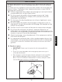
IMPORTANT! Do not scratch the sensor when cleaning the spout
(Ill. 12).
Avoid using any cleaning materials that may scratch the spout
surface.
To safely clean the surface, wipe it using a dampened soft cloth with
diluted dishwashing detergent and dry it with another soft cloth.
If this does not adequately clean the surface, wipe the area with a
neutral detergent and wet cloth.
Ill. 12

12
ENGLISH
MAINTENTANCE
Check your faucet at least once a month for the following potential problems
and to do the following maintenance procedures:
Inspect for Leakage
Check all water connections for signs of leakage.
Tighten the Spout
If the spout is loose, tighten the hexagonal nut underneath the spout.
Adjust the Temperature
For thermostatic mixing models, turn the temperature control handle a
few times a year. Buildup may form inside the valve, resulting in impaired
performance if maintenance is not regularly performed.
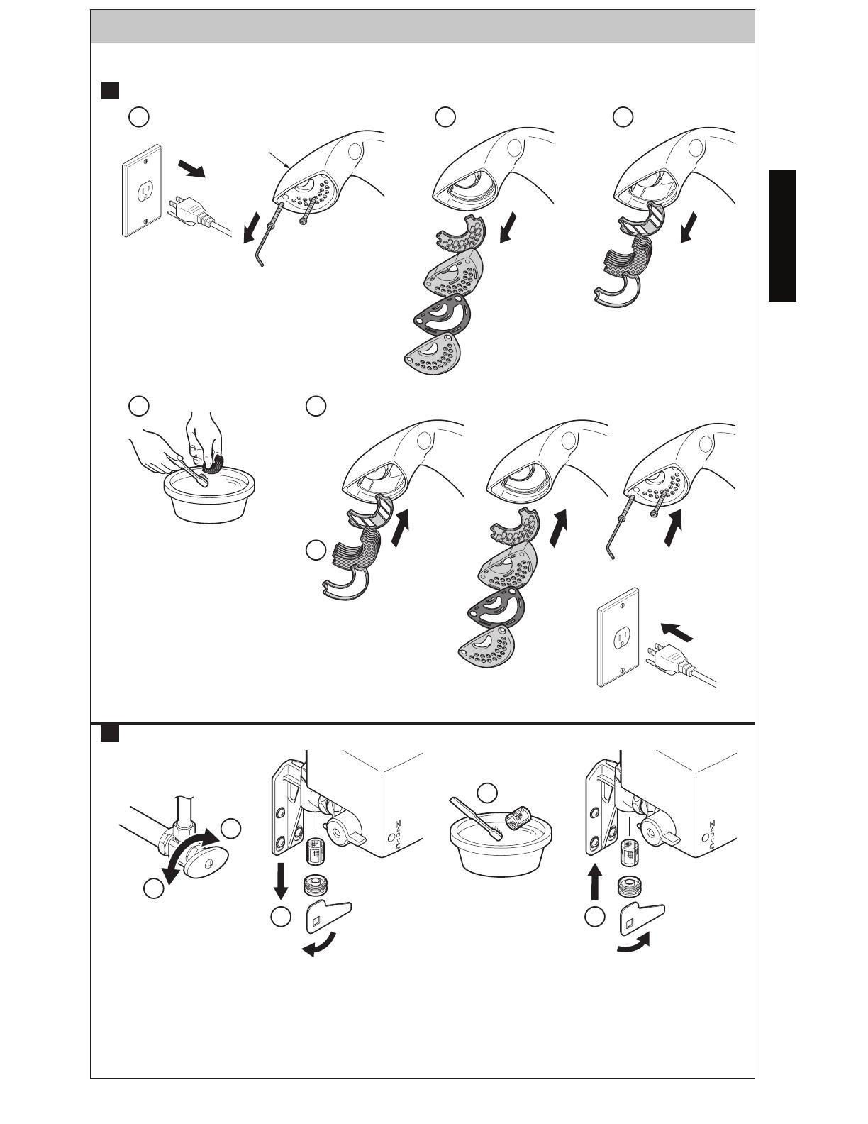
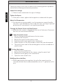
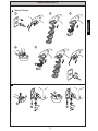
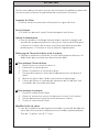
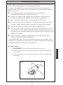
Cleaning the Nozzle Screen and Inlet Strainer
When the inlet strainer is clogged the flow rate will decrease. Decreased
flow rate can lead to diminished flow.
To clean the nozzle screen:
1. Pull out the power plug and remove the two screws.
2. Dismount the four parts.
3. Remove the spacer and the nozzle screen.
4. Scrub the nozzle screen gently with a tooth brush.
5. Mount the parts in the reverse order in which they were dismounted.
6. The nozzle screen and the flow-dividing plate must be assembled in a
specific order.
To clean the strainer:
1. Close the water shutoff valve.
2. Remove the lid and take out the strainer, using the special tool.
3. Scrub the strainer gently with a tooth brush.
4. Open the water shutoff valve.
Modifying the outlet flow
When modifying the flow regulator, the outlet flow control must be
serviced with only Toto’s recommended flow rate of 1.1 gallon/min (4.2 L/
min).
A
B
13
ENGLISH
Nozzle Screen
MAINTENTANCE
1
1
5
5
6
2
2
3
3
4
4
Maintenance
GB
Mantenimiento
ES
Entretien
FR
Manutenção
PT
A
B
A
-7-
Strainer

14
ENGLISH
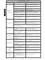
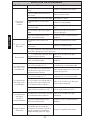
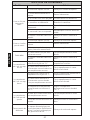
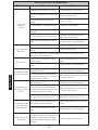
TROUBLESHOOTING
Problem Cause Solution
Water won’t
begin
running.
The surface of the sensor is
dirty.
Clean the surface of the sensor.
There is an obstruction in front
of the sensor.
Remove the obstruction.
The stop valve is turned off. Turn on the valve.
The controller is unplugged. Plug in the controller.
The sensor connector is dis-
connected.
Securely attach the connector(s).
Water service is suspended. Wait until the water service is restored.
The strainer or the nozzle
screen is clogged.
Clean the strainer and the nozzle
screen.
Water won’t stop
running
The surface of the sensor is
dirty.
Clean the surface of the sensor.
There is an obstruction in front
of the sensor.
Remove the obstruction.
If the water continues to run after attempting the above solutions, turn
off the stop valve.
Low flow rate
The stop valve is not fully
opened.
Open the stop valve fully.
The strainer or the nozzle
screen is clogged.
Clean the strainer and the nozzle
screen.
Water tempera-
ture is too high
The temperature control
handle is set at “H”.
Set the temperature control handle to
the middle point.
The stop valve connected to
the cold-water supply is not
fully opened.
Open the cold-water stop valve fully.
Water tempera-
ture is too low
The temperature control
handle is set at “C”.
Set the temperature control handle to
the middle point.
The stop valve connected to
the hot water supply is not
fully opened.
Open the hot water stop valve fully.
The hot water supply temper-
ature is lower than 120°F.
Set the hot water supply temperature
to 120°F.
Water
temperature
adjusts
incorrectly
One side of the stop valve is
not fully opened.
Open the stop valve fully.
The strainer or the nozzle
screen is clogged.
Clean the strainer and the nozzle
screen .
Short detection
range
The self-adjusting sensor
may not work properly when
strained or blocked by water
droplets.
Clean the sensor surface.

15
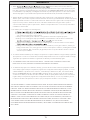
ENGLISH
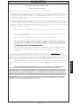
WARRANTY
1. TOTO ers (“Product”) to be free from defects in
materials and workmanship during normal use when properly installed and serviced, for a period of three (3) years
from date of purchase. This limited warranty is extended only to the ORIGINAL PURCHASER of the Product and is
not transferable to any third party, including but not limited to any subsequent purchaser or owner of the Product.
This warranty applies only to TOTO Product purchased and installed in North, Central and South America.
2. TOTO’s obligations under this warranty are limited to repair, replacement or other appropriate adjustment, at
TOTO’s option, of the Product or parts found to be defective in normal use, provided that such Product was properly
sa snoitcepsni hcus ekam ot thgir eht sevreser OTOT .snoitcurtsni htiw ecnadrocca ni decivres dna desu ,dellatsni
ni strap ro robal rof egrahc ton lliw OTOT .tcefed eht fo esuac eht enimreted ot redro ni yrassecen eb yam
connection with warranty repairs or replacements. TOTO is not responsible for the cost of removal, return and/or
reinstallation of the Product.
5. THIS WARRANTY GIVES YOU SPECIFIC LEGAL RIGHTS. YOU MAY HAVE OTHER RIGHTS WHICH VARY
FROM STATE TO STATE, PROVINCE TO PROVINCE OR COUNTRY TO COUNTRY.
6. To obtain warranty repair service under this warranty, you must take the Product or deliver it prepaid to a TOTO
service facility together with proof of purchase (original sales receipt) and a letter stating the problem, or contact
a TOTO distributor or products service contractor, or write directly to TOTO U.S.A., INC., 1155 Southern Road,
Morrow, GA 30260 (888) 295 8134 or (678) 466-1300, if outside the U.S.A. If, because of the size of the Product
or nature of the defect, the Product cannot be returned to TOTO, receipt by TOTO of written notice of the defect
esoohc yam OTOT ,esac hcus nI .yreviled etutitsnoc llahs )tpiecer selas lanigiro( esahcrup fo foorp htiw rehtegot
to repair the Product at the purchaser’s location or pay to transport the Product to a service facility.
THIS WRITTEN WARRANTY IS THE ONLY WARRANTY MADE BY TOTO. REPAIR, REPLACEMENT OR OTHER APPROPRIATE
ADJUSTMENT AS PROVIDED UNDER THIS WARRANTY SHALL BE THE EXCLUSIVE REMEDY AVAILABLE TO THE ORIGINAL
PURCHASER. TOTO SHALL NOT BE RESPONSIBLE FOR LOSS OF THE PRODUCT OR FOR OTHER INCIDENTAL, SPECIAL
OR CONSEQUENTIAL DAMAGES OR EXPENSES INCURRED BY THE ORIGINAL PURCHASER, OR FOR LABOR OR OTHER
COSTS DUE TO INSTALLATION OR REMOVAL, OR COSTS OF REPAIRS BY OTHERS, OR FOR ANY OTHER EXPENSE NOT
SPECIFICALLY STATED ABOVE. IN NO EVENT WILL TOTO’S RESPONSIBILITY EXCEED THE PURCHASE PRICE OF THE
PRODUCT. EXCEPT TO THE EXTENT PROHIBITED BY APPLICABLE LAW, ANY IMPLIED WARRANTIES, INCLUDING THAT
OF MERCHANTABILITY OR FITNESS FOR USE OR FOR A PARTICULAR PURPOSE, ARE EXPRESSLY DISCLAIMED. SOME
STATES DO NOT ALLOW LIMITATIONS ON HOW LONG AN IMPLIED WARRANTY LASTS, OR THE EXCLUSION OR
LIMITATION OF INCIDENTAL OR CONSEQUENTIAL DAMAGES, SO THE ABOVE LIMITATION AND EXCLUSION MAY NOT
APPLY TO YOU.
3. This warranty does not apply to the following items:
b. Damage or loss resulting from any accident, unreasonable use, misuse, abuse, negligence, or improper
care, cleaning, or maintenance of the Product.
c. Damage or loss resulting from sediments or foreign matter contained in a liquid soap system.
ro/dna hsrah a ni tcudorP eht fo noitallatsni morf ro noitallatsni reporpmi morf gnitluser ssol ro egamaD .d
tion of the Product.
e. Damage or loss resulting from electrical surges or lightning strikes or other acts which are not the fault of
f. Damage or loss resulting from normal and customary wear and tear, such as gloss reduction, scratching or
fading over time due to use, cleaning practices or water or atmospheric conditions, including but not limited
to, the use of bleach, alkali, acid cleaners, dry (powder) cleaners or any other abrasive cleaners or the use
of metal or nylon scrubbers.
4. In order for this limited warranty to be valid, proof of purchase is required. TOTO encourages warranty registration
upon purchase to create a record of Product ownership at http://www.totousa.com is required. TOTO encourages
registration upon purchase and failure to register will not diminish you r limited warranty rights.

16
ESPAÑOL
¡GRACIAS POR ELEGIR TOTO!
La misión de TOTO es dar al mundo estilos de vida más saludables, higiénicos y
cómodos. Diseñamos cada producto guiándonos por el principio del equilibrio entre
forma y función. Felicitaciones por su elección.
¡
Gracias Por Elegir TOTO!................16
Advertencias.......................................16
Antes de la Instalación.......................17
Piezas Incluidas..................................18
Herramientas Que Va A Necesitar....18
Especificaciones.................................18
Procedimiento de Instalación...........19
Pruebas y Calibración........................22
Como Utilizar......................................23
Ajuste Del Modo................................23
Cuidado y Limpieza...........................25
Mantenimiento...................................26
Solucion De Problemas.....................28
Garantia ..............................................29
Bosquejo ............................................58
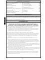
TABLA DE CONTENIDO
POR FAVOR, LEA ESTAS SALVAGUARDAS IMPORTANTES PARA SU
SEGURIDAD Y PARA PREVENIR DAÑOS AL PRODUCTO Y PROPIEDAD.
⚠ Para asegurar que la instalación del producto se realice de forma correcta, lea con
cuidado este manual por completo antes de iniciar la instalación..
⚠ Siga todas las instrucciones precedidas del símbolo de precaución (⚠) o la etiqueta
de (AVISO) para evitar peligros potenciales que puedan causar lesiones o muerte,
choque eléctrico, daños a la propiedad o invalidar la garantía.
⚠ Cumpla siempre con todas las normas de fontanería de su localidad.
⚠ Asegúrese de que el suministro de agua esté cerrado antes de iniciar la instalación.
⚠ Nunca desarme, repare o modifique el producto de ninguna manera que no esté
descrita en este manual. De ser necesario, envíe el producto a un ingeniero de
servicio.
⚠ No bloquee el flujo de agua de la apertura de la boca del grifo durante su uso.
⚠ Monte la salida en un lugar a más de 100 mm del piso. Seleccione la ubicación de
montaje de la salida para que la condensación en la tubería de suministro de agua y
el agua salpicada durante el uso del producto no entre en contacto con la salida, o
considere utilizar un enchufe a prueba de agua.
⚠ No use agua suministrada a más de 185ºF (85ºC). Para evitar quemaduras debido a un
funcionamiento incorrecto, ajuste la presión del suministro de agua fría a una presión
superior a la del suministro de agua caliente oa la misma presión.
⚠ No invierta las entradas de agua fría y caliente.
⚠ No lo instale en los siguientes ambientes: en exteriores, en ubicaciones húmedas tales
como saunas, ubicaciones heladas o vehículos en movimiento. Si la temperatura baja
hasta el punto de congelación, envuelva las tuberías con aislamiento.
⚠ Evite colocar cualquier objeto dentro del rango de detección del sensor infrarrojo.
⚠ Cierre siempre la llave de paso antes de limpiar el filtro y espere a que el filtro del
lado del agua caliente se enfríe.
ADVERTENCIAS
17
ESPAÑOL
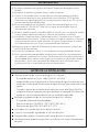
ADVERTENCIAS
⚠ No limpie el producto con agentes de limpieza excepto con detergente neutro
diluido.
⚠ No someta el producto a grandes fuerzas, caídas o impactos.
⚠ Conecte el controlador solo a una toma de corriente protegida con interruptor
de circuito con descarga a tierra (ground fault circuit interrupter, GFCI) que esté
conectada a un supresor de picos con un valor nominal de no más de 15 A. No use
una toma de corriente dañada o floja.
⚠ No use este producto con ninguna otra fuente de alimentación que no sea la
especificada (AC 100-240 VAC, 50/60 Hz). La fuente de voltaje debe tener un
interruptor por separado.
⚠ No dañar, modificar (cortar o extender), doblar a la fuerza, girar, tirar, pellizcar, enrollar,
calentar o poner objetos pesados en el cable de alimentación o el enchufe.
⚠ Desenchufe siempre tomando el enchufe por su base. Cuando lo inserte, hágalo
completamente hasta la base. No moje el enchufe o las partes eléctricas, ni inserte o
extraiga el enchufe con las manos húmedas. Asegúrese siempre de que el enchufe
esté limpio de polvo o tierra. Evite su operación durante tormentas.
⚠ Asegúrese de que el cable de alimentación no entre en contacto con la tubería de
suministro de agua caliente.
⚠ Desenchufe el producto si no se va a utilizar durante un largo período de tiempo.
⚠ Realice un mantenimiento periódico. No permita que anomalías, tales como partes
que golpetean, queden sin ser resueltas. Por lo menos una vez al año, inspeccione el
área alrededor de las tuberías en busca de fugas, remplace las válvulas de retención
desgastadas y gire la manija de control de temperatura de la válvula de mezcla
térmica para evitar la acumulación de sarro o el atascamiento.
ANTES DE LA INSTALACIÓN
Verifique la presión del suministro de agua fría y caliente.
El rango de presión es 15 psi - 80psi (100 kPa - 551 kPa).
Asegúrese de ajustar la presión de la alimentación de agua fría para que sea
mayor que la presión de alimentación de agua caliente, o para que ambas sean
iguales.
Cuando la presión de alimentación de agua sea mayor que 80psi (551kPa),
asegúrese de bajar la presión para que quede en un rango de 20 a 80psi por
medio una válvula reductora de presión (se vende por separado).
Verifique la temperatura de los suministros de agua fría y caliente.
El rango de temperatura recomendado:
Suministro de agua CALIENTE: 120ºF-180ºF (49ºC-82ºC)
Suministro de agua FRÍA: 39ºF-80ºF (4ºC-27ºC)
Lave todas las líneas de agua antes de la instalación.
Cierre el suministro de agua desde las válvulas de cierre.
Asegúrese de no dañar la superficie del sensor durante la instalación.
No coloque otros dispositivos que usen un inversor o un sensor infrarrojo cerca
del grifo.

18
ESPAÑOL
Tornillos (8)
Llave
Controlador Soportes de Montaje (2)
Asegurese que usted tiene las piezas indicadas aqui debajo:
PIEZAS INCLUIDAS
HERRAMIENTAS QUE VA A NECESITAR
Taladro
Destornillador
Phillips
Lápiz
Nivel
Cinta
Métrica
ESPECIFICACIONES
A F
H
G
I
B
C
D
J
E
Fuente de Alimentación AC 100~240 V
Longitud del cable de ali-
mentación
29-1/2” (750mm)
Sensor de Deteccion
de Distancia
5-1/8’”~ 7-7/8” (130~200mm)
Sensor es auto-ajustable.
Presión del Suministro de Agua
Minimo Requerido: 15 psi (138 kPa) (Flowing)
Maximo permitido: 80 psi (551 kPa)
Conexión de
Suministro de Agua
1/2-14 NSPM
Rango de Temperatura de
Entrada
CALIENTE: 120~180°F (49~82°C)*
FRIO: 39~80°F (4~27°C)
Temperatura Ambiente 32~104°F (0~40°C)
Humedad Max. 90% RH
Tasa de Flujo Maximo 1.1 galón/min (4.2 L/min)
Conjunto de Boca del Grifo
* Verifique sus códigos de plomería locales.

19
ESPAÑOL
NOTA:
Antes de instalar el grifo, asegurese de
limpiar bien las mangueras de suministro
de cualquier tipo de polvo. Cierre el
suministro de agua en las válvulas de
cierre. Consulte la página de dimensiones
preliminares para determinar la ubicación
correcta del controlador.
1. Monte los soportes de la entrada en
la pared (ill. 1). Use anclajes de muro
de ser necesario (no se incluyen). Los
soportes DEBEN montarse a 3-¾”
(95mm) uno del otro (centro a centro)
para conectarse correctamente al
controlador. Asegúrese de que no
haya obstrucciones en los soportes
de entrada.
PROCEDIMIENTO DE INSTALACIÓN
F
G
H
I
H
I
J
J
I
95mm
IMPORTANTE!
Asegúrese de montar cada soporte
de entrada de agua en la posición
vertical correcta tal como se muestra.
De otra forma, no se podrá tener
acceso al cedazo en el soporte de la
entrada de agua para su limpieza.
2. Remover la cubierta del controlador
(ill. 2).
3. Conecte la manguera flexible al soporte de entrada (ill. 3).
ill. 1
ill. 2
ill. 3
I
20
ESPAÑOL
4. Sujetar la boquilla (ill. 4).
5. Corte las mangueras
si es necesario (ill. 5).
Asegúrese de que los
cortes sean cuadrados.
6. Conecte la manguera (ill 6).
PROCEDIMIENTO DE INSTALACIÓN
A
B
C
ill. 4
90
A
D
ill. 5
H
D
ill. 6
A página está carregando...
A página está carregando...
A página está carregando...
A página está carregando...
A página está carregando...
A página está carregando...
A página está carregando...
A página está carregando...
A página está carregando...
A página está carregando...
A página está carregando...
A página está carregando...
A página está carregando...
A página está carregando...
A página está carregando...
A página está carregando...
A página está carregando...
A página está carregando...
A página está carregando...
A página está carregando...
A página está carregando...
A página está carregando...
A página está carregando...
A página está carregando...
A página está carregando...
A página está carregando...
A página está carregando...
A página está carregando...
A página está carregando...
A página está carregando...
A página está carregando...
A página está carregando...
A página está carregando...
A página está carregando...
A página está carregando...
A página está carregando...
A página está carregando...
A página está carregando...
A página está carregando...
A página está carregando...
-
 1
1
-
 2
2
-
 3
3
-
 4
4
-
 5
5
-
 6
6
-
 7
7
-
 8
8
-
 9
9
-
 10
10
-
 11
11
-
 12
12
-
 13
13
-
 14
14
-
 15
15
-
 16
16
-
 17
17
-
 18
18
-
 19
19
-
 20
20
-
 21
21
-
 22
22
-
 23
23
-
 24
24
-
 25
25
-
 26
26
-
 27
27
-
 28
28
-
 29
29
-
 30
30
-
 31
31
-
 32
32
-
 33
33
-
 34
34
-
 35
35
-
 36
36
-
 37
37
-
 38
38
-
 39
39
-
 40
40
-
 41
41
-
 42
42
-
 43
43
-
 44
44
-
 45
45
-
 46
46
-
 47
47
-
 48
48
-
 49
49
-
 50
50
-
 51
51
-
 52
52
-
 53
53
-
 54
54
-
 55
55
-
 56
56
-
 57
57
-
 58
58
-
 59
59
-
 60
60


Toto TLP01701U Installation and Owner's Manual
- Categoria
- Louças sanitárias
- Tipo
- Installation and Owner's Manual
- Este manual também é adequado para
em outras línguas
- español: Toto TLP01701U
- français: Toto TLP01701U
- English: Toto TLP01701U
Artigos relacionados
-
Toto EcoPower Automatic Faucets Guia de instalação
-
-
Toto Helix-M Tels12 Serie Manual do usuário
-
-
-
-
-
-
-
