Dell PowerEdge C6105 Guia rápido

Tipo
Guia rápido
Dell PowerEdge
C6105
Getting Started
With Your System
Guide de mise en route du système
Introdução ao Uso do Sistema
Introducción al sistema
Dell PowerEdge
C6105
Getting Started
With Your System
Notes, Cautions, and Warnings
NOTE:
A NOTE indicates important information that helps you make better use of
your computer.
CAUTION: A CAUTION indicates potential damage to hardware or loss of
data if instructions are not followed.
WARNING: A WARNING indicates a potential for property damage,
personal injury, or death.
______________
Information in this document is subject to change without notice.
© 2013 Dell Inc. All rights reserved.
Reproduction of these materials in any manner whatsoever without the written permission
of Dell Inc. is strictly forbidden.
Trademarks used in this text: Dell™, the DELL logo, and PowerEdge™ are trademarks of
Dell Inc. AMD® is a registered trademark and AMD Opteron™ is a trademark of
Advanced Micro Devices, Inc. Red Hat Enterprise Linux® and Enterprise Linux® are
registered trademarks of Red Hat, Inc. in the United States and/or other countries.
Novell® is a registered trademark and SUSE™ is a trademark of Novell Inc. in the United
States and other countries. Citrix® and XenServer® are either registered trademarks or
trademarks of Citrix Systems, Inc. in the United States and/or other countries. VMware®
is a registered trademarks or trademarks of VMWare, Inc. in the United States or other
countries.
Other trademarks and trade names may be used in this publication to refer to either the
entities claiming the marks and names or their products. Dell Inc. disclaims any
proprietary interest in trademarks and trade names other than its own.
Regulatory Model B03S
November 2013 P/N 45F0M Rev. A05
Getting Started With Your System | 3
CAUTION: Restricted Access Location
This server is intended for installation only in restricted access locations as
defined in Cl. 1.2.7.3 of IEC 60950-1: 2001 where both these conditions apply:
Access can only be gained by service persons or by users
who have been
instructed about the reasons for the restrictions applied to the location and
about any precautions that shall be taken.
Access is through the use of a tool or lock and key, or other means of
security, and is controlled by the authority responsible for the location.
Installation and Configuration
WARNING: Before performing the following procedure, review and follow the
safety instructions that came with the system.
Unpacking the System
Unpack your system and identify each item.
Installing the Tool-Less Rail Solution
WARNING: Whenever you need to lift the system, get others to assist you.
To avoid injury, do not attempt to lift the system by yourself.
WARNING: The system is not fixed to the rack or mounted on the rails. To
avoid personal injury or damage to the system, you must adequately
support the system during installation and removal.
WARNING: To avoid a potential electrical shock hazard, a third wire safety
grounding conductor is necessary for the rack installation. The rack
equipment must provide sufficient airflow to the system to maintain proper
cooling.
CAUTION: When installing rails in a square-hole rack it is important to
ensure that the square peg slides through the square holes.
Getting Started With Your System | 4
1
Align the end pieces of the rails on the vertical rack flanges to seat
the pegs in the bottom hole of the first U and the top hole of the
second U. Engage the back end of the rails until the latches lock in
place.
NOTE:
The rails can be used in both square-hole (item 1 in the following figure)
and round-hole racks (item 2 in the following figure).
Figure 1. Pushing the Latch Release Buttons
2
Repeat Step 1 to position and seat the front end pieces on the vertical
flanges.
NOTE:
To remove the rails, pull on the latch release button on the end piece
midpoint and unseat each rail.
3
Slide the system into the rack.
4
If present, remove the chassis stabilizer shipping bracket (optional)
from the rack.
NOTE:
To transport systems already installed in the rack, ensure that the two
chassis stabilizer shipping brackets (optional) are in place.
Getting Started With Your System | 5
Figure 2. Installing the Chassis Stabilizer Shipping Brackets
5
Tighten the thumbscrews to secure the ears of the system to the front
of the rack flanges.
Figure 3. Installing the Chassis onto the Rack.
Getting Started With Your System | 6
Optional-Connecting the Keyboard, Mouse, and Monitor
Figure 4. Optional—Connecting the Keyboard, Mouse and Monitor
Connect the keyboard, mouse, and monitor (optional).
The connectors on the back of your system have icons indicating which cable to
plug into each connector. Be sure to tighten the screws (if any) on the monitor’s
cable connector.
Getting Started With Your System | 7
Connecting the Power Cable(s)
Figure 5. Connecting the Power Cable
Connect the system’s power cable(s) to the system and, if a monitor is used,
connect the monitor’s power cable to the monitor. Plug the other end of the
power cables into a grounded electrical outlet or a separate power source such as
an uninterrupted power supply or a power distribution unit.
Getting Started With Your System | 8
Turning on the System
Figure 6. Pressing the Power Button on the Front of the System and the Monitor
Figure 7. Pressing the Power Button on the Back of the System
Press the power button(s) either on the front or back of the system and on the
monitor. The power indicators should light.
Getting Started With Your System | 9
Complete the Operating System Setup
To install an operating system for the first time, see the installation and
configuration documentation for your operating system. Be sure the operating
system is installed before installing hardware or software not purchased with the
system.
NOTE:
For the latest information on supported operating systems, see
dell.com/ossupport.
Other Information You May Need
WARNING: See the safety and regulatory information that shipped with your
system. Warranty information may be included within this document or as a
separate document.
The Hardware Owner’s Manual provides information about system features and
describes how to troubleshoot the system and install or replace system
components. This document is available at
dell.com/support/manuals
.
Dell systems management application documentation provides information
about installing and using the systems management software. This document is
available online at
dell.com/support/manuals
.
NOTE:
Always check for updates on
dell.com/support/manuals
and read the
updates first because they often supersede information in other documents.
Getting Started With Your System | 10
NOM Information (Mexico Only)
The following information is provided on the device described in this document
in compliance with the requirements of the official Mexican standards (NOM):
Importer Dell Inc. de México, S.A. de C.V.
Paseo de la Reforma 2620-11° Piso
Col. Lomas Atlas
11950 México, D.F.
Model number
B03S
Supply voltage 100-240 V AC with 470 W/750
W/1100 W Power
200-240 V AC with 1400 W Power
Frequency
50/60 Hz
Current consumption 6.5-3.5 Amps with 470 W Power
8.6 Amps with 1400 W Power
9.5-5.0 Amps with 750 W Power
12-6.7 Amps with 1100 W Power
Getting Started With Your System | 11
Technical Specifications
Processor (Per System Board)
Processor type One or two AMD C32 Series processors
One or two AMD Opteron 4000 Series
processors
One or two AMD Opteron 4200 Series
processors
One or two AMD Opteron 4300 Series
processors
Expansion Bus (Per System Board)
Bus type
PCI Express Generation 2
Expansion slots
PCIe
One x16, half-length, half-height
Daughter card PCIe
One x8, custom slot
Memory (Per System Board)
Architecture 12 x DDR3 800/1066/1333/1600* MHz
registered memory modules with /ECC
Memory module sockets
12 x DDR3 DIMM sockets
Memory module capacities 2 GB, 4 GB, 8 GB, or 16 GB
Minimum RAM 12 GB
Maximum RAM
192 GB
NOTE:
System memory working frequency is up to 1333MT/s only.
Drives
Hard drives Up to twelve 3.5-inch, hot-swappable
SAS/SATA drives or up to twenty four 2.5-
inch, hot-swappable SAS/SATA/SSD drives
NOTE:
SAS hard drives are supported by add-on card.
Getting Started With Your System | 12
Connectors (Per System Board)
Back
NIC
Two RJ-45 (10/100/1000 Mbps Ethernet)
Serial
9-pin, DTE, 16550-compatible
USB Two 4-pin, USB 2.0-compliant
Video
15-pin D-Sub VGA
Management port Dedicated Ethernet port for remote
management access
Video (Per System Board)
Video type On-board AST2050 video controller or
AST1100
Video memory
8 MB
Power
AC power supply (per power supply)
Wattage 470 W
Voltage
100-240 VAC, 50-60 Hz, input current
range: 6.5-3.5 Amps
Heat dissipation 2390 BTU/hr maximum
Wattage
750 W
Voltage 100-240 VAC, 50-60 Hz, input current
range: 9.5-5.0 Amps
Heat dissipation
3414 BTU/hr maximum
Wattage
1023 W low line/1100W high line
Voltage 100-240 VAC, 50-60 Hz, input current
range: 12.0-6.7 Amps
Heat dissipation
4575 BTU/hr maximum
Wattage 1400 W
Voltage
200-240 VAC, 50-60 Hz, maximum input
current: 9.6 Amps
Heat dissipation 5432 BTU/hr maximum
Getting Started With Your System | 13
Maximum inrush current Initial In-rush Current cannot exceed 55
Amps (peak). Secondary In-rush Current
cannot exceed 35 Amps (peak).
Battery (per system board)
System battery
CR 2032 3.0-V lithium ion coin cell
RAID battery (optional)
3.7-V lithium ion battery pack
Physical
Height
8.76 cm (3.45 in)
Width 44.8 cm (17.6 in)
Depth 75.1 cm (29.47 in)
Weight (maximum
configuration)
33.67 kg (74.2 lb)
Weight (empty) 15.11 kg (33.32 lb)
Environmental
NOTE:
For additional information about environmental measurements for specific system
configurations, see
www.dell.com/environmental_datasheets
.
Temperature
Operating 10° to 35°C (50° to 95°F) with a maximum
temperature gradation of 10°C per hour
NOTE:
For altitudes above 2950 feet, the maximum
operating temperature is derated 1°F/550 ft.
Storage 40° to 65°C (40° to 149°F) with a
maximum temperature gradation of 20°C per
hour
Relative humidity
Operating 20% to 80% (noncondensing) with a
maximum humidity gradation of 10% per
hour
Storage
5% to 90% (noncondensing)
Maximum vibration
Operating
0.26 Grms at 5350 Hz
Storage
1.93 Grms at 10500 Hz for 15 min
Getting Started With Your System | 14
Maximum shock
Operating One shock pulse in the positive z axis
(one pulse on each side of the system) of
31 G for 2.6 ms in the operational orientation
Storage Six consecutively executed shock pulses in
the positive and negative x, y, and z axes
(one pulse on each side of the system) of
71 G for up to 2 ms;
Six consecutively executed shock pulses in
the positive and negative x, y, and z axes
(one pulse on each side of the system)
of 27 G faired square wave pulse with
velocity change at 235 inches/second
(597 centimeters/second)
Altitude
Operating 16 to 3,048 m (50 to 10,000 ft)
NOTE:
For altitudes above 2950 feet, the maximum
operating temperature is derated 1°F/550 ft.
Storage
16 to 10,600 m (50 to 35,000 ft)
Airborne contaminant level
Class
G2 or lower as defined by ISA-S71.04-1985
Dell PowerEdge
C6105
Guide de mise en
route du système
Remarques, précautions et
avertissements
REMARQUE
: indique des informations importantes qui peuvent vous aider à mieux
utiliser votre ordinateur.
PRÉCAUTION : une PRÉCAUTION indique un risque d'endommagement du
matériel ou de perte de données en cas de non respect des instructions.
AVERTISSEMENT : un AVERTISSEMENT indique un risque
d'endommagement du matériel, de blessure corporelle ou de mort.
Les informations contenues dans ce document peuvent être modifiées sans préavis.
© 2013 Dell Inc. Tous droits réservés.
La reproduction du présent document, de quelque manière que ce soit, sans l'autorisation
écrite de Dell Inc. est strictement interdite.
Les marques utilisées dans ce document : Dell™, le logo DELL logo et PowerEdgesont
des marques de Dell Inc. AMD® est une marque déposée et AMD Opteron™ est une
marque d'Advanced Micro Devices, Inc. Red Hat Enterprise Linux® et Enterprise Linux®
sont des marques déposées de Red Hat, Inc. aux États-Unis et/ou dans d'autres pays.
Novell® est une marque déposée et SUSE™ est une marque de Novell Inc. aux États-Unis
et dans d'autres pays. Citrix® et XenServer® sont des marques déposées ou des marques
de Citrix Systems, Inc. aux États-Unis et/ou dans d'autres pays. VMware® est une marque
déposée ou une marque de VMware, Inc. aux États-Unis ou dans d'autres pays.
D'autres marques et noms de marque peuvent être utilisés dans ce document pour faire
référence aux entités se réclamant de ces marques et de ces noms ou de leurs produits.
Dell Inc. décline tout intérêt exclusif dans les marques et les noms commerciaux autres
que les siens.
Modèle réglementaire B03S
Novembre 2013 P/N 45F0M Rév. A05
Guide de mise en route du système | 17
PRÉCAUTION : Zone à accès restreint
Ce serveur est conçu pour être installé uniquement dans des zones à
accès restreint telles que définies selon la norme Cl. 1.2.7.3 de IEC
60950-1: 2001 où ces deux conditions s'appliquent :
Seuls peuvent avoir accès le personnel d'entretien et les utilisateurs
qui ont été informés des motifs des restrictions appliquées à
l'emplacement et des précautions à prendre.
L'accès, qui se fait par l'intermédiaire d'un outil ou d'un verrou et
d'une clé, ou par d'autres moyens de sécurité, est contrôlé par le
responsable en charge de l'emplacement.
Installation et configuration
AVERTISSEMENT : avant de commencer la procédure suivante, lisez et
respectez les consignes de sécurité fournies avec le système.
Déballage du système
Sortez le système de son emballage et identifiez chaque élément.
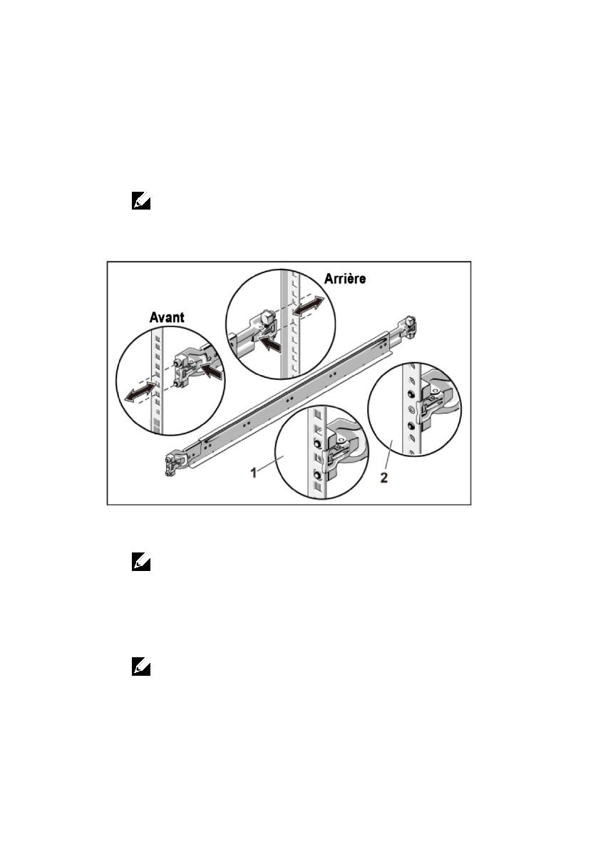
Installation des rails sans outils
AVERTISSEMENT : demandez toujours de l'aide avant de soulever le
système. N'essayez pas de le soulever seul, car vous risqueriez de vous
blesser.
AVERTISSEMENT : le système n'est fixé ni au rack ni aux rails. Vous devez
le soutenir correctement au cours de l'installation et du retrait pour éviter
de l'endommager ou de vous blesser.
AVERTISSEMENT : afin d'éviter une éventuelle électrocution, assurez-vous
de disposer d'un troisième conducteur de mise à la terre pour l'installation
du rack. L'équipement du rack doit assurer une ventilation suffisante pour
bien refroidir le système.
PRÉCAUTION : lorsque vous installez des rails dans un rack à trous
carrés, vérifiez que les taquets de fixation à tête carrée glissent bien dans
les trous carrés.
Guide de mise en route du système | 18
1
Alignez l'embout des rails sur les collerettes verticales pour
que les taquets de fixation s'insèrent dans le trou du bas de la
première unité en U et le trou du haut de la deuxième unité
en U. Glissez l'arrière du rail jusqu'à enclenchement du
loquet.
REMARQUE :
les rails peuvent aussi bien être utilisés dans un rack à trous
carrés (élément 1 dans la figure ci-dessous) que dans un rack à trous ronds
(élément 2 dans la figure ci-dessous).
Figure 1. Appuyer sur les boutons de dégagement du loquet
2
Répétez
l'étape 1
pour positionner et fixer les embouts avant
des rails sur la collerette verticale.
REMARQUE :
pour retirer les rails, appuyez sur le bouton de dégagement du
loquet situé au milieu de l'embout et dégagez les rails un par un.
3
Glissez le système dans le rack.
4
Si les deux supports d'expédition du stabilisateur de châssis
(en option) sont présents, retirez-les du rack.
REMARQUE :
avant de transporter des systèmes déjà installés dans le rack,
assurez-vous que les deux supports d'expédition du stabilisateur de châssis
(en option) sont en place.
  • Page 1 1
  • Page 2 2
  • Page 3 3
  • Page 4 4
  • Page 5 5
  • Page 6 6
  • Page 7 7
  • Page 8 8
  • Page 9 9
  • Page 10 10
  • Page 11 11
  • Page 12 12
  • Page 13 13
  • Page 14 14
  • Page 15 15
  • Page 16 16
  • Page 17 17
  • Page 18 18
  • Page 19 19
  • Page 20 20
  • Page 21 21
  • Page 22 22
  • Page 23 23
  • Page 24 24
  • Page 25 25
  • Page 26 26
  • Page 27 27
  • Page 28 28
  • Page 29 29
  • Page 30 30
  • Page 31 31
  • Page 32 32
  • Page 33 33
  • Page 34 34
  • Page 35 35
  • Page 36 36
  • Page 37 37
  • Page 38 38
  • Page 39 39
  • Page 40 40
  • Page 41 41
  • Page 42 42
  • Page 43 43
  • Page 44 44
  • Page 45 45
  • Page 46 46
  • Page 47 47
  • Page 48 48
  • Page 49 49
  • Page 50 50
  • Page 51 51
  • Page 52 52
  • Page 53 53
  • Page 54 54
  • Page 55 55
  • Page 56 56
  • Page 57 57
  • Page 58 58
  • Page 59 59
  • Page 60 60
  • Page 61 61
  • Page 62 62

Dell PowerEdge C6105 Guia rápido

Tipo
Guia rápido