Yamaha NS-P210 Manual do proprietário
- Categoria
- Subwoofers
- Tipo
- Manual do proprietário
Este manual também é adequado para

NS-P210
HOME CINEMA 5.1CH SPEAKER PACKAGE
5.1 SYSTEM D’ENCEINTES HOME CINEMA
OWNER’S MANUAL
MODE D’EMPLOI
BEDIENUNGSANLEITUNG
BRUKSANVISNING
MANUALE DI ISTRUZIONI
MANUAL DE INSTRUCCIONES
GEBRUIKSAANWIJZING
G B

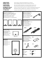
● Audio connection cord
● Câble de connexion audio
● Audio-Anschlußkabel
● Audio anslutningssladd
● Cavo di collegamento audio
● Cable de conexión de audio
● Audio aansluitkabel
● Speaker cords
● Câbles d’enceintes
● Lautsprecheranschlußkabel
● Högtalarledningar
● Cavi per gli altoparlanti
● Cables de los altavoces
● Luidsprekerdraden
● Mounting brackets
● Supports de montage
● Befestigungshalterungen
● Monteringsfästen
● Staffe di montaggio
● Ménsulas de instalación
● Montagesteunen
● Screws
● Vis
● Schrauben
● Skruvar
● Viti
● Tornillos
● Schroeven
● Main and rear speakers
● Enceintes principales et arrière
● Haupt- und hinteres Lautsprecherpaar
● Huvudhögtalare och bakre högtalare
● Altoparlanti principali e posteriori
● Altavoces principales y traseros
● Hoofdluidsprekers en achterluidsprekers
● Center speaker
● Enceinte centrale
● Centerlautsprecher
● Mitthögtalare
● Altoparlante centrale
● Altavoz central
● Middenluidspreker
● Subwoofer
● Subwoofer
● Subwoofer
● Subwooferhögtalaren
● Subwoofer
● Altavoz ultragraves
● Subwoofer
UNPACKING After unpacking, check that the following items are contained.
DEBALLAGE Après le déballage, vérifier que les pièces suivantes sont incluses.
AUSPACKEN Nach dem Auspacken überprüfen, ob die folgenden Teile vorhanden sind.
UPPACKNING Kontrollera efter det apparaten packats upp att följande delar finns med.
DISIMBALLAGGIO Verificare che tutte le parti seguenti siano contenute nell’imballaggio dell’apparecchio.
DESEMBALAJE Desembale el aparato y verifique que los siguientes accesorios están en la caja.
UITPAKKEN Controleer na het uitpakken of de volgende onderdelen voorhanden zijn.
(A)
(B)
[4m] [15m]
(A)
(B)
(C)
X 3
X 2
X 5
X 8
X 2
X 3
X 2
<NX-210P><NX-210P><NX-210P><NX-210P>
<NX-C210>
<SW-P201>

English
E-1
●
To assure the finest performance, please read this manual
carefully. Keep it in a safe place for future reference.
●
Install the speakers in a cool, dry, clean place – away from
windows, heat sources, sources of excessive vibration,
dust, moisture and cold. Avoid sources of humming
(transformers, motors). To prevent fire or electrical shock,
do not expose the speakers to rain or water.
● To prevent the enclosure from warping or discoloring, do
not place the speakers where they will be exposed to
direct sunlight or excessive humidity.
● Do not place the speakers where they are liable to be
knocked over or struck by falling objects. Stable
placement will also ensure better sound performance.
● Placing the speakers on the same shelf or rack as the
turntable can result in feedback.
● Any time you note distortion, reduce the volume control
on your amplifier to a lower setting. Never allow your
amplifier to be driven into “clipping”. Otherwise the
speakers may be damaged.
●
When using an amplifier with a rated output power higher
than the nominal input power of the speakers, care should
be taken never to exceed the speakers’ maximum input.
● As these speakers contain strong magnets (though all of
them are magnetically shielded types), avoid placing
watches, magnetic tapes, etc. near them. Also, placing
the speakers near a TV set may impair picture color. If
this happens, move the speakers away from the TV set.
●
Do not attempt to clean the speakers with chemical solvents
as this might damage the finish. Use a clean, dry cloth.
● Secure placement or installation is the owner’s
responsibility.
YAMAHA shall not be liable for any accident caused
by improper placement or installation of speakers.
For U.K. customers
If the socket outlets in the home are not suitable for the plug
supplied with this appliance, it should be cut off and an
appropriate 3 pin plug fitted. For details, refer to the
instructions described below.
Note: The plug severed from the mains lead must be
destroyed, as a plug with bared flexible cord is hazardous if
engaged in a live socket outlet.
SPECIAL INSTRUCTIONS FOR U.K. MODEL
IMPORTANT:
THE WIRES IN MAINS LEAD ARE COLOURED IN
ACCORDANCE WITH THE FOLLOWING CODE:
Blue: NEUTRAL
Brown: LIVE
As the colours of the wires in the mains lead of this
apparatus may not correspond with the coloured markings
identifying the terminals in your plug, proceed as follows:
The wire which is coloured BLUE must be connected to
the terminal which is marked with the letter N or coloured
BLACK. The wire which is coloured BROWN must be
connected to the terminal which is marked with the letter L
or coloured RED. Making sure that neither core is
connected to the earth terminal of the three pin plug.
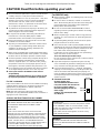
CAUTION: Read this before operating your unit.
Thank you for selecting this YAMAHA NS-P210 Speaker Package.
For SW-P201 only
● Never open the cabinet. If something drops into the set,
contact your dealer.
● Do not use force on switches, controls or connection
wires. When moving the unit, first disconnect the power
plug and the wires connected to other equipments.
Never pull the wires themselves.
● Be sure to read the “TROUBLESHOOTING” section
regarding common operating errors before concluding
that the unit is faulty.
● When not planning to use this unit for a long period (ie.,
vacation, etc.), disconnect the AC power plug from the
wall outlet.
●
To prevent lightning damage, disconnect the AC power
plug when there is an electric storm.
● Since this unit has a built-in power amplifier, heat will
radiate from the rear panel. Place the unit apart from the
walls, allowing enough space above, behind and on the
both sides of the unit to prevent fire or damage.
Furthermore, do not position with the rear panel facing
down on the floor or other surfaces.
<For U.K. and Europe models only>
Be sure to allow a space of at least 20 cm above, behind
and on both sides of the unit.
● Super-bass frequencies reproduced by this unit may
cause a turntable to generate a howling sound. In such a
case, move this unit away from the turntable.
● If you hear distorted noise (i.e., unnatural, intermittent
“rapping” or “hammering” sounds) coming from this unit,
reduce the volume level. Extremely loud playing of a
movie soundtrack’s low frequency, bass-heavy sounds or
similarly loud popular music passages can damage this
speaker system.
● VOLTAGE SELECTOR
(General model only)
The VOLTAGE SELECTOR on the
rear panel of this unit must be set
for your local main voltage
BEFORE plugging into the AC
main supply.
Voltages are 110-120/220-240 V
AC, 50/60 Hz.
Standby mode
If the POWER switch is set to the ON position and the
AUTO STANDBY switch is set to the HIGH or LOW
position, this unit turns into the standby mode when no
signal is inputted to this unit.
In this state, this unit is designed to consume a very
small quantity of power.
WARNING
TO REDUCE THE RISK OF FIRE OR ELECTRIC
SHOCK, DO NOT EXPOSE THIS UNIT TO RAIN OR
MOISTURE.
VOLTAGE
SELECTOR
220V-240V
110V-120V

E-2
CONTENTS
UNPACKING.................... Inside of Front Cover
CAUTION .........................................................1
COMPONENTS OF THE PACKAGE .............. 2
SETTING UP THE SPEAKERS ...................... 3
Placing the subwoofer ................................... 3
Mounting the main and center speakers .......... 4
Mounting the rear speakers............................ 5
CONNECTIONS.............................................. 6
General information for connections ............ 6
An example of basic connections.................... 6
How to connect speaker cords to the input
and output terminals of the speakers
............... 7
Various ways of connecting the subwoofer
.... 8
Connecting the subwoofer to line output
(pin jack) terminals of the amplifier
(The basic way) ................................................. 8
Connecting the subwoofer to speaker output
terminals of the amplifier
................................ 9
USING THE SUBWOOFER (SW-P201)........ 10
Controls and their functions.......................... 10
Adjusting the subwoofer before use ......... 11
ADVANCED YAMAHA ACTIVE SERVO
TECHNOLOGY (for SW-P201) .................... 12
TROUBLESHOOTING (for SW-P201) ......... 13
SPECIFICATIONS ........................................ 14
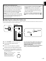
COMPONENTS OF THE PACKAGE
The speaker package “NS-P210” is designed for use in a multi-channel audio system such as a home theater system.
The package includes two pairs of main/rear speakers (NX-210P), a center speaker (NX-C210) and a subwoofer system (SW-
P201).
<Main/rear speakers (NX-210P)>
Full-range acoustic-suspension speaker system
<Center speaker (NX-C210)>
Full-range acoustic-suspension speaker system
<Subwoofer (SW-P201)>
Active Servo Processing Subwoofer System with a
built-in power amplifier
● This subwoofer system employs Advanced YAMAHA
Active Servo Technology which YAMAHA has developed
for reproducing higher quality super-bass sound. (Refer to
page 12 for details on Advanced YAMAHA Active Servo
Technology.) This super-bass sound adds a more
realistic, theater-in-the-home effect to your stereo system.
● This subwoofer can be easily added to your existing
audio system by connecting to either the speaker
terminals or the line output (pin jack) terminals of the
amplifier.
● The AUTO STANDBY switch saves you the trouble of
setting the POWER switch to the ON or OFF position.

English
E-3
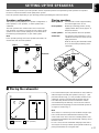
m Placing the subwoofer
It is recommended to place the subwoofer on the outside of
either the right or the left main speaker. (See fig. Å .) The
placement shown in fig. ı is also possible, however, if the
subwoofer system is placed directly facing the wall, the
bass effect may die because the sound from it and the
sound reflected by the wall may cancel out each other. To
prevent this from happening, face the subwoofer system at
an angle as shown in fig. Å.
Note
There may be a case that you cannot obtain enough super-
bass sounds from the subwoofer when listening in the
center of the room. This is because “standing waves” have
been developed between two parallel walls and they cancel
the bass sounds.
In such a case, face the subwoofer obliquely to the wall. It
also may be necessary to break up the parallel surfaces by
placing bookshelves etc. along the walls.
( : Subwoofer, : Main speaker)
ı
Å
SETTING UP THE SPEAKERS
Before making connections, place all speakers in their respective positions. The positioning of the speakers is important
because it controls the whole sound quality of this system.
Place the speakers depending on your listening position by following the instructions below.
Speaker configuration
This speaker package employs a 6 speaker configuration: 2
main speakers, 2 rear speakers, a center speaker and a
subwoofer.
The main speakers are used for main source sound. The
rear speakers are used for surround sounds, and the center
speaker is for center sounds (dialog etc.). The subwoofer is
for reinforcing low frequencies on your audio system.
Note
In this speaker package, the same speakers (NX-210P) are
used for the main and rear speakers.
Placing speakers
Main speakers: On both sides of and at approximately
the same height as the TV set.
Rear speakers: Behind your listening position, facing
slightly inward. About 1.8 m (approx. 6
feet) from the floor.
Center speaker: Precisely between the main speakers.
Subwoofer: The position of the subwoofer is not so
critical because low bass tones are not
highly directional.
Refer to “Placing the subwoofer” below
for a recommended positioning of the
subwoofer.
Main L Center Main R
Rear L
Subwoofer
Rear R
Main L
Main R
Subwoofer
Center
Rear L
Rear R
TV-set

E-4
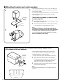
Place the main speakers on a rack or on a shelf. Place the
center speaker on top of the TV, on a shelf or inside the TV
rack so that it is stable.
To obtain more stability and usefulness, we recommend that
you mount these speakers on the provided mounting
brackets (type A).
To mount the speakers on the mounting
brackets (type A)
1 Attach the bracket to the bottom of the speaker by using
the provided screw (type A).
2 Turn and/or slide the speaker on the bracket according
to your preference, and then tighten the screw.
Note
Though this speaker is a magnetically shielded type,
there may be some influence on a TV picture depending
on the type of TV or the placement of the speaker. In
such a case, place the speaker apart from TV so that
there is no influence on TV picture.
m Mounting the main and center speakers
1
2
The provided mounting bracket (type C) with 1 pair of
screw holes (at an interval of 60 mm) can be used to
mount the speaker on a speaker stand.
* Those screw holes can be used with M4 screws only.
1 Attach the bracket to the bottom of the speaker by
using the provided screw (type A) so that the convex
part of the bracket fits in the grooved part on the
bottom of the speaker as shown on the left.
2 Mount the speaker on the speaker stand by using the
screw holes on the bracket.
Note
The mounting bracket (type C) is provided for each of 5
speakers.
If you want to mount a speaker on a commercially available speaker stand
(for the main/center/rear speakers)
Mounting
bracket
(type A)
Screw
(type A)
Mounting
bracket
(type C)
Screw
(type A)
60 mm

English
E-5
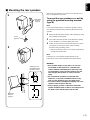
Mount the rear speakers on a shelf, rack or directly on the
floor, or hang them on the wall.
To mount the rear speakers on a wall by
using the provided mounting brackets
(type B)
Note
It is recommended that you connect the speaker cords to
the speaker’s terminals before attaching the bracket to the
speaker.
1 Attach the bracket to the bottom of the speaker by using
the provided screw (type B).
2 Turn and/or slide the speaker on the bracket according
to your preference, and then, tighten the screw.
3 Fasten screws into a firm wall or wall support as shown
in the figure, and hang the holes of the mounting
bracket on the protruding screws.
* Make sure that the screws are securely caught by the
narrow parts of the holes.
Note
If desired, you can hang the speaker directly on the
protruding screws on the wall without using the bracket.
WARNING
● Each speaker weighs 0.7 kg (1 lbs. 9 oz.). Do not
mount them on thin plywood or a wall with soft
surface material. If mounted, the screws may come
out of the flimsy surface and the speakers may fall.
This damages the speakers or causes personal
injury.
● Do not install the speakers to a wall with nails,
adhesives, or any other unstable hardware. Long-
term use and vibrations may cause them to fall.
● To avoid accidents resulting from tripping over loose
speaker cords, fix them to the wall.
● Select a proper position on the wall to mount the
speaker and the bracket so that no one will injure his/
her head or face with the edge of the bracket.
m Mounting the rear speakers
1
2
3
Mounting
bracket
(type B)
Screw
(type B)
Mounting
bracket
(type B)
Wall/ wall
support
Tapping screw
(Available at the
hardware store)
Min.
12 mm
65 mm

E-6
CONNECTIONS
Caution: Plug in the subwoofer and other audio/video components after all connections are
completed.
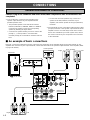
● Connect the main, center and rear speakers to the
speaker output terminals of your amplifier with the
provided speaker cords.
* The provided speaker cords have labels marked
FRONT L, FRONT R, CENTER, REAR L or REAR R.
Connect each speaker cord to the corresponding
speaker by following the figure below.
* Connect each speaker making sure not to reverse the
polarity (+, –). If the speaker is connected with
reversed polarity, the sound will be unnatural and lack
bass.
* For the main and rear speakers only, connect one
speaker to the left (marked L) terminals of your
amplifier, and another speaker to the right (marked R)
terminals.
● The subwoofer can be connected to either the line output
(pin jack) terminals or the speaker output terminals of the
amplifier. Choose one of the ways shown in this section
that is more suitable for your audio system. Also, refer to
the owner’s manual of your component to be connected
to the subwoofer.
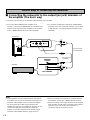
m An example of basic connections
Basically, connect the subwoofer to the line output (pin jack) terminal(s) of the amplifier. (Refer to page 8 for details.) If your
amplifier does not have any line output terminal, connect the subwoofer to the speaker output terminals of the amplifier. (Refer
to page 9 for details.)
SPEAKERS
MAIN CENTER REAR
(SURROUND)
OUTPUT
SUB
WOOFER
CAUTION
SEE INSTRUCTION
MANUAL FOR CORRECT SETTING.
MAIN
A
B
A
B
CENTER REAR
(SURROUND)
/MONO
VOLUME
INPUT1
FROM AMPLIFIER
OUTPUT
TO SPEAKERS
INPUT2
AUTO
STANDBY
STANDBY-RED
ON-GREEN
OFF
LOW
HIGH
OFF
POWER
ON
0I0
INPUT2
/MONO
REAR R
REAR L
REAR R
CENTER
REAR L
CENTER
FRONT R
FRONT R
FRONT L
FRONT L
LeftRight
Subwoofer
Amplifier
To AC outlet
Center speaker
Rear speakers
LeftRight
Main speakers
General information for connections

English
E-7
Main/center/rear speakers
One side of the provided speaker cord has a white broken
line and the other side has no line.
Connect the (+) terminals on both the speaker and the
amplifier using the side with a white broken line. Connect
the (–) terminals on both components using the side with no
line.
Red: positive (+)
Black: negative (–)
Subwoofer (INPUT1/OUTPUT terminals)
Connect the (+) terminals on both the subwoofer and the
amplifier using one side of the cord. Connect the (–)
terminals on both components using the other side of the
cord.
Red: positive (+)
Black: negative (–)
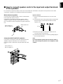
m How to connect speaker cords to the input and output terminals
of the speakers
For connections, keep the speaker cords as short as possible. Do not bundle or roll up the excess part of the cords. If the
connections are faulty, no sound will be heard from the speakers.
10 mm
How to Connect:
1 Press and hold the terminal’s tab, as shown in the
figure.
2 Insert the bare wire end properly into the terminal hole.
[Remove approx. 10 mm (3/8”) insulation from the
speaker cord.]
3 Release your finger from the tab to allow it to lock
securely on the cord’s wire end.
4 Test the firmness of the connection by pulling lightly on
the cord at the terminal.
Note
Do not let the bare speaker wires touch each other as
this could damage the speaker or the amplifier, or both
of them.
White broken line

E-8
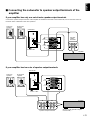
Notes
● Some amplifiers have line output terminals labeled PRE
OUT. When you connect the subwoofer to the PRE OUT
terminals of the amplifier, make sure that the amplifier
has at least two sets of PRE OUT terminals. If the
amplifier has only one set of PRE OUT terminals, do not
connect the subwoofer to the PRE OUT terminals.
Instead, connect the subwoofer to the speaker output
terminals of the amplifier. (Refer to pages 6 and 7.)
● When connecting to a monaural line output terminal of
the amplifier, connect the L/MONO INPUT2 terminal.
● When connecting to line output terminals of the amplifier,
other speakers should not be connected to the OUTPUT
terminals on the rear panel of the subwoofer. If
connected, they will not produce sound.
Subwoofer
Amplifier
Pin plug cord
(included)
To AC outlet
Various ways of connecting the subwoofer
● To connect with a YAMAHA DSP amplifier (or AV
receiver), connect the SUBWOOFER (or LOW PASS etc.)
terminal on the rear of the DSP amplifier (or AV receiver)
to the L/MONO INPUT2 terminal of the subwoofer.
m Connecting the subwoofer to line output (pin jack) terminals of
the amplifier (The basic way)
Connect the main speakers to the speaker output terminals of the amplifier.
● To connect the subwoofer to the SPLIT SUBWOOFER
terminals on the rear of the DSP amplifier, connect them
to both the left L and right R INPUT2 terminals of the
subwoofer.
/MONO
VOLUME
INPUT1
FROM AMPLIFIER
OUTPUT
TO SPEAKERS
INPUT2
AUTO
STANDBY
STANDBY-RED
ON-GREEN
OFF
LOW
HIGH
OFF
POWER
ON
0I0
SPLIT SUBWOOFER
SUBWOOFER
(LOW PASS)
INPUT2
/MONO
Pin plug cords
(not included)

English
E-9
m Connecting the subwoofer to speaker output terminals of the
amplifier
If your amplifier has only one set of main speaker output terminals
Connect the speaker output terminals of the amplifier to the INPUT1 terminals of the subwoofer, and connect the OUTPUT
terminals of the subwoofer to the main speakers.
Left main
speaker
Right main
speaker
Subwoofer
Amplifier
Speaker
output
terminals
To AC outlet
If your amplifier has two sets of speaker output terminals
(Both A and B speaker outputs
must be ON.)
Subwoofer
Amplifier
Speaker output terminals
To AC outlet
/MONO
VOLUME
INPUT1
FROM AMPLIFIER
OUTPUT
TO SPEAKERS
INPUT2
AUTO
STANDBY
STANDBY-RED
ON-GREEN
OFF
LOW
HIGH
OFF
POWER
ON
0I0
INPUT1
FROM AMPLIFIER
OUTPUT
TO SPEAKERS
/MONO
VOLUME
INPUT1
FROM AMPLIFIER
OUTPUT
TO SPEAKERS
INPUT2
AUTO
STANDBY
STANDBY-RED
ON-GREEN
OFF
LOW
HIGH
OFF
POWER
ON
0I0
AB
INPUT1
FROM AMPLIFIER
OUTPUT
TO SPEAKERS
Left main
speaker
Right main
speaker

E-10
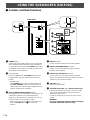
USING THE SUBWOOFER (SW-P201)
1 POWER switch
Set this switch to the ON position to turn on the power
of the subwoofer. When the power of the subwoofer is
on, the power indicator below the POWER switch lights
up GREEN. Set this switch to the OFF position to turn
off the power of the subwoofer.
2 Power indicator
Lights up GREEN when the POWER switch is set to
the ON position and goes off when set to the OFF
position.
* Standby mode
If the POWER switch is set to the ON position and
the AUTO STANDBY switch is set to the HIGH or
LOW position, this indicator lights up RED when no
signal is inputted to the subwoofer.
3 AUTO STANDBY (HIGH/LOW/OFF) switch
By setting this switch to the HIGH or LOW position, the
subwoofer’s automatic power-switching function
operates as described on the next page. If you do not
need this function, set to the OFF position.
* Make sure to change the setting of this switch only
when the POWER switch (1) is in the OFF
position.
4 INPUT2 terminals
Used to input line level signals from the amplifier.
5 INPUT1 (FROM AMPLIFIER) terminals
Used to connect the subwoofer with the speaker
terminals of the amplifier.
6 OUTPUT (TO SPEAKERS) terminals
Can be used for connecting to the main speakers.
Signals are sent directly from the amplifier to the main
speakers by way of these terminals.
7 VOLUME control
Adjusts the volume level.
8 VOLTAGE SELECTOR switch (General model only)
If the preset setting of the switch is incorrect, set the
switch to the proper voltage range (220V-240V or
110V-120V) of your area.
Consult your dealer if you are unsure of the correct
setting.
WARNING
Be sure to unplug the subwoofer before setting the
VOLTAGE SELECTOR switch correctly.
Rear panel
m Controls and their functions
INPUT1
FROM AMPLIFIER
OUTPUT
TO SPEAKERS
INPUT2
/MONO
AUTO
STANDBY
STANDBY-RED
ON-GREEN
OFF
LOW
HIGH
OFF
POWER
ON
1
VOLUME
0I0
OFF
POWER
ON
5
6
4
INPUT1
FROM AMPLIFIER
OUTPUT
TO SPEAKERS
INPUT2
/MONO
AUTO
STANDBY
STANDBY-RED
ON-GREEN
OFF
LOW
HIGH
VOLUME
0I0
2
3
7
VOLTAGE
SELECTOR
220V-240V
110V-120V
VOLTAGE
SELECTOR
220V-240V
110V-120V
8

English
E-11
1 Set the VOLUME control to minimum (0).
2 Turn on the power supply to all the
components.
3 Play a source and adjust the amplifier’s
volume control to the desired listening level.
4 Increase the volume gradually to adjust the
volume balance between the subwoofer and
the main speakers.
Note: It is recommended to set the
VOLUME control to the middle
position when using all the
speakers of this package in a 5.1-
channel home theater system.
m Adjusting the subwoofer before use
Before using the subwoofer, adjust the subwoofer to obtain the optimum volume balance between the subwoofer and the main
speakers by following the procedures described below.
Rear panel
Once the volume balance between the subwoofer and
the main speakers is adjusted, you can adjust the
volume of your whole sound system by using the
amplifier’s volume control.
However, if you change the main speakers NX-210P to
others, you must make this adjustment again.
INPUT1
FROM AMPLIFIER
OUTPUT
TO SPEAKERS
INPUT2
/MONO
AUTO
STANDBY
STANDBY-RED
ON-GREEN
OFF
LOW
HIGH
OFF
POWER
ON
2
VOLUME
0I0
OFF
POWER
ON
AUTO
STANDBY
STANDBY-RED
ON-GREEN
OFF
LOW
HIGH
VOLUME
0I0
1, 4
VOLUME
0I0
Automatic power-switching function
When you play a source, the power of the subwoofer turns
on automatically by sensing audio signals input to the
subwoofer. On the other hand, the subwoofer automatically
switches to the standby mode if the source being played is
stopped or the input signal is cut off for a few minutes.
This function operates by sensing a certain level of low
frequency input signal. Its sensitivity is high in the HIGH
position and low in the LOW position of the AUTO
STANDBY switch. Set this switch to the position you prefer.
In the HIGH position, the power will turn on even with a low
level of input signal. But please be aware that the subwoofer
may not switch to the standby mode when there is an
extremely low input signal.
* The power might turn on unexpectedly by sensing noise
from other appliances. If that occurs, set the AUTO
STANDBY switch to the OFF or LOW position.
* The level of low frequency input signal differs with each
source and among different parts within the same
source. This means that the function may not operate
properly on some sources.
This function is available only when the power of the
subwoofer is on (by setting the POWER switch (1) to
“ON”).

E-12
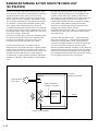
ADVANCED YAMAHA ACTIVE SERVO TECHNOLOGY
(for SW-P201)
The theory of Yamaha Active Servo Technology has been
based upon two major factors, the Helmholtz resonator and
negative-impedance drive. Active Servo Processing
speakers reproduce the bass frequencies through an “air
woofer”, which is a port or opening in the speaker’s cabinet.
This opening is used instead of, and performs the functions
of, a woofer in a conventionally designed speaker system.
Thus, signals of low amplitude within the cabinet can,
according to the Helmholtz resonance theory, be outputted
from this opening as waves of great amplitude if the size of
the opening and the volume of the cabinet are in the correct
proportion to satisfy a certain ratio.
In order to accomplish this, moreover, the amplitudes within
the cabinet must be both precise and of sufficient power
because these amplitudes must overcome the “load”
presented by the air that exists within the cabinet.
Thus it is this problem that is resolved through the
employment of a new design in which the amplifier supplies
special signals. If the electrical resistance of the voice coil
could be reduced to zero, the movement of the speaker unit
would become linear with respect to signal voltage. To
accomplish this, a special negative-impedance output-drive
amplifier for subtracting output impedance of the amplifier is
used.
By employing negative-impedance drive circuits, the
amplifier is able to generate precise, low-amplitude, low-
frequency waves with superior damping characteristics.
These waves are then radiated from the cabinet opening as
high-amplitude signals. The system can, therefore, by
employing the negative-impedance output drive amplifier
and a speaker cabinet with the Helmholtz resonator,
reproduce an extremely wide range of frequencies with
amazing sound quality and less distortion.
The features described above, then, are combined to be the
fundamental structure of the conventional Yamaha Active
Servo Technology.
Our new Active Servo Technology — Advanced Yamaha
Active Servo Technology — adopted Advanced Negative
Impedance Converter (ANIC) circuits, which allows the
conventional negative impedance converter to dynamically
vary in order to select an optimum value for speaker
impedance variation. With this new ANIC circuits, Advanced
Yamaha Active Servo Technology can provide more stable
performance and improved sound pressure compared with
the conventional Yamaha Active Servo Technology, resulting
in more natural and dynamic bass reproduction.
High-amplitude
bass sound
Cabinet
Port
Air woofer
(Helmholtz resonator)
Active Servo
Processing
Amplifier
Signals
Signals of low amplitude
Advanced Negative-
impedance Converter

English
E-13
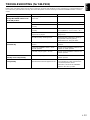
Problem
Power is not supplied even
though the POWER switch is set
to the ON position.
No sound.
Sound level is too low.
The subwoofer will not turn on
automatically.
The subwoofer turns into the
standby mode unexpectedly.
The subwoofer turns on
unexpectedly.
What to Do
Connect it securely.
Turn the VOLUME control to the right.
Connect them securely.
Connect them correctly, that is L (left) to
L, R (right) to R, “+” to “+” and “–” to “–”.
Play a source sound with bass
frequencies.
Reposition the subwoofer or break up
the parallel surface by placing
bookshelves etc. along the walls.
Set the POWER switch to the ON
position.
Set the AUTO STANDBY switch to the
“HIGH” or “LOW” position.
Set the AUTO STANDBY switch to the
“HIGH” position.
Set the AUTO STANDBY switch to the
“HIGH” position.
Move the subwoofer farther away from
such appliances and/or reposition the
connected speaker cables.
Otherwise, set the AUTO STANDBY
switch to the “OFF” position.
Cause
The power plug is not securely
connected.
The VOLUME control is set to 0.
Speaker cords are not connected
securely.
Speaker cords are not connected
correctly.
A source sound with few bass
frequencies is played.
It is influenced by standing waves.
The POWER switch is set to the OFF
position.
The AUTO STANDBY switch is set to
the OFF position.
The level of input signal is too low.
The level of input signal is too low.
There is an influence of noise
generated from external appliances etc.
TROUBLESHOOTING (for SW-P201)
Refer to the chart below when this unit does not function properly. If the problem you are experiencing is not listed below or if
the instructions given below do not help, disconnect the power cord and contact your authorized YAMAHA dealer or service
center.

E-14
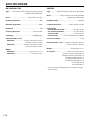
SPECIFICATIONS
NX-210P, NX-C210
Type .........Full-range acoustic-suspension speaker system
Magnetically shielded type
Driver............................................. 8 cm (3-1/8”) cone type
Nominal Input Power ................................................. 30W
Maximum Input Power ............................................. 100W
Impedance .....................................................................6Ω
Frequency Response..................................65 Hz–20 kHz
Sensitivity ...................................................86 dB/2.83V/m
Dimensions (W x H x D)
<NX-210P>........................ 100 mm x 140 mm x 113 mm
(3-15/16” x 5-1/2” x 4-7/16”)
<NX-C210> ....................... 140 mm x 100 mm x 112 mm
(5-1/2” x 3-15/16”x 4-7/16”)
Weight
<NX-210P>.................................. 0.7 kg (1 lbs. 9 oz.) x 4
<NX-C210> ....................................... 0.7 kg (1 lbs. 9 oz.)
SW-P201
Type ............... Advanced Yamaha Active Servo Technology
Driver...................... 16 cm (6-5/16”) cone woofer (JA1678)
Magnetically shielded type
Amplifier Output.................................................... 50W/5Ω
Frequency Response................... 30 Hz–200 Hz (–10 dB)
Power Supply
USA and Canada models ....................... AC 120V, 60 Hz
U.K. and Europe models ........................ AC 230V, 50 Hz
Australia model....................................... AC 240V, 50 Hz
General model.............. AC 110-120/220-240V, 50/60 Hz
Power Consumption ...................................................42W
Dimensions (W x H x D)...... 200 mm x 395 mm x 384 mm
(7-7/8” x 15-9/16” x 15-1/8”)
Weight .................................................9.3 kg (20 lbs. 7 oz.)
Accessories ...............................Audio connection cord x 1
Speaker cord [4 m (13.1 feet)] x 3
Speaker cord [15 m (49.2 feet)] x 2
Mounting bracket (type A) x 3
Mounting bracket (type B) x 2
Mounting bracket (type C) x 5
Screw (type A) x 8
Screw (type B) x 2
* Please note that all specifications are subject to change
without notice.

N-14
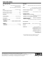
SPECIFICATIES
NX-210P, NX-C210
Type ............................... Full range akoestische-suspensie
luidsprekersysteem
Type met magnetische afscherming
Driver.................................................... 8 cm konus-woofer
Nominaal ingangsvermogen ..................................... 30W
Maximaal ingangsvermogen ................................... 100W
Impedantie .....................................................................6Ω
Frekwentiebereik..................................... 65 Hz tot 20 kHz
Gevoeligheid .............................................86 dB/2,83W/m
Afmetingen (L x H x B)
<NX-210P>........................ 100 mm x 140 mm x 113 mm
<NX-C210> ....................... 140 mm x 100 mm x 112 mm
Gewicht
<NX-210P>....................................................... 0,7 kg x 4
<NX-C210> ............................................................0,7 kg
SW-P201
Type ............... Advanced Yamaha Active Servo Technology
Driver.................................. 16 cm konus-woofer (JA1678)
Type met magnetische afscherming
Versterker-uitgangsvermogen ............................. 50W/5Ω
Frekwentiebereik...................... 30 Hz tot 200 Hz (–10 dB)
Spanningsvereisten
Modellen voor U.S.A. en Canada
.................................................. 120V, 60 Hz wisselstroom
Modellen voor Groot-Brittannië en Europa
.................................................. 230V, 50 Hz wisselstroom
Modellen voor Australië ......... 240V, 50 Hz wisselstroom
Algemene modellen
........................110-120/220-240V, 50/60 Hz wisselstroom
Stroomverbruik ...........................................................42W
Afmetingen (L x H x B)........ 200 mm x 395 mm x 384 mm
Gewicht ..................................................................... 9,3 kg
Toebehoren.................................... Audio aansluitkabel x 1
Luidsprekerdraad (4 m) x 3
Luidsprekerdraad (15 m) x 2
Montagesteun (type A) x 3
Montagesteun (type B) x 2
Montagesteun (type C) x 5
Schroef (type A) x 8
Schroef (type B) x 2
* Alle specificaties zijn onder voorbehoud en kunnen
zondere nadere kennisgeving worden gewijzigd.
YAMAHA ELECTRONICS CORPORATION, USA 6660 ORANGETHORPE AVE., BUENA PARK, CALIF. 90620, U.S.A.
YAMAHA CANADA MUSIC LTD. 135 MILNER AVE., SCARBOROUGH, ONTARIO M1S 3R1, CANADA
YAMAHA ELECTRONIK EUROPA G.m.b.H. SIEMENSSTR. 22-34, 25462 RELLINGEN BEI HAMBURG, F.R. OF GERMANY
YAMAHA ELECTRONIQUE FRANCE S.A. RUE AMBROISE CROIZAT BP70 CROISSY-BEAUBOURG 77312 MARNE-LA-VALLEE CEDEX02, FRANCE
YAMAHA ELECTRONICS (UK) LTD. YAMAHA HOUSE, 200 RICKMANSWORTH ROAD WATFORD, HERTS WD1 7JS, ENGLAND
YAMAHA SCANDINAVIA A.B. J A WETTERGRENS GATA 1, BOX 30053, 400 43 VÄSTRA FRÖLUNDA, SWEDEN
YAMAHA MUSIC AUSTRALIA PTY, LTD. 17-33 MARKET ST., SOUTH MELBOURNE, 3205 VIC., AUSTRALIA
Printed in China
V601210
-
 1
1
-
 2
2
-
 3
3
-
 4
4
-
 5
5
-
 6
6
-
 7
7
-
 8
8
-
 9
9
-
 10
10
-
 11
11
-
 12
12
-
 13
13
-
 14
14
-
 15
15
-
 16
16
-
 17
17


Yamaha NS-P210 Manual do proprietário
- Categoria
- Subwoofers
- Tipo
- Manual do proprietário
- Este manual também é adequado para
em outras línguas
- español: Yamaha NS-P210 El manual del propietario
- français: Yamaha NS-P210 Le manuel du propriétaire
- italiano: Yamaha NS-P210 Manuale del proprietario
- English: Yamaha NS-P210 Owner's manual
- русский: Yamaha NS-P210 Инструкция по применению
- Nederlands: Yamaha NS-P210 de handleiding
- Deutsch: Yamaha NS-P210 Bedienungsanleitung
- dansk: Yamaha NS-P210 Brugervejledning
- čeština: Yamaha NS-P210 Návod k obsluze
- svenska: Yamaha NS-P210 Bruksanvisning
- polski: Yamaha NS-P210 Instrukcja obsługi
- Türkçe: Yamaha NS-P210 El kitabı
- suomi: Yamaha NS-P210 Omistajan opas
- română: Yamaha NS-P210 Manualul proprietarului
Artigos relacionados
-
Yamaha SW-2 Manual do proprietário
-
-
Yamaha YST-SW45 Manual do usuário
-
-
-
-
-
-
-