Sony XM-GTX6041 Manual do proprietário
- Categoria
- Alto-falantes do carro
- Tipo
- Manual do proprietário

XM-GTX6041_BR [GB/PT] 4-300-771-31(1)
4-300-771-31(1)
Operating instructions
Manual de instruções
XM-GTX6041
Stereo Power Amplifier
Precautions
This unit is designed for negative ground 12 V DC
operation only.
Use speakers with an impedance of 2 to 8 Ω
(4 to 8 Ω when used as a bridging amplifier).
Do not connect any active speakers (with built-in
amplifiers) to the speaker terminals of the unit.
Doing so may damage the active speakers.
Avoid installing the unit in areas subject to:
— high temperatures such as from direct sunlight
or hot air from the heater
— rain or moisture
— dust or dirt.
If your car is parked in direct sunlight and there is a
considerable rise in temperature inside the car,
allow the unit to cool down before use.
When installing the unit horizontally, be sure not to
cover the fins with the floor carpet etc.
If this unit is placed too close to the car audio unit
or antenna, interference may occur. In this case,
relocate the amplifier away from the car audio unit
or antenna.
If no power is being supplied to the car audio unit,
check the connections.
This power amplifier employs a protection circuit*
to protect the transistors and speakers if the
amplifier malfunctions. Do not attempt to test the
protection circuits by covering the heat sink or
connecting improper loads.
Do not use the unit on a weak battery as its
optimum performance depends on a good power
supply.
For safety reasons, keep your car audio unit volume
moderate so that you can still hear sounds outside
your car.
Fuse Replacement
If the fuse blows, check the power connection and
replace both the fuses. If the fuse blows again after
replacement, there may be an internal malfunction. In
such a case, consult your nearest Sony dealer.
Warning
When replacing the fuse, be sure to use one matching
the amperage stated above the fuse holder. Never use
a fuse with an amperage rating exceeding the one
supplied with the unit as this could damage the unit.
* Protection circuit
This amplifier is provided with a protection circuit that
operates in the following cases:
— when the unit is overheated
— when a DC current is generated
— when the speaker terminals are short-circuited.
The color of the POWER/PROTECTOR indicator will change
from green to red, and the unit will shut down.
If this happens, turn off the connected equipment, take out
the cassette tape or disc, and determine the cause of the
malfunction. If the amplifier has overheated, wait until the
unit cools down before use.
If you have any questions or problems concerning
your unit that are not covered in this manual, please
consult your nearest Sony dealer.
Features
The power output of each channel is 90 W RMS
(at 4 Ω).
Built in Low-pass filter (80 Hz, 18 dB/oct) and
High-pass filter (80 Hz, 12 dB/oct).
Protection circuit and indicator provided.
Pulse power supply* for stable and regulated output
power.
* Pulse power supply
This unit has a built-in power regulator which converts the
power supplied by the 12 V DC car battery into high speed
pulses using a semiconductor switch. These pulses are
stepped up by the built-in pulse transformer and separated
into both positive and negative power supplies before
being converted into direct current again. This is to
regulate fluctuating voltage from the car battery. This light
weight power supply system provides a highly efficient
power supply with a low impedance output.
Características
A potência de saída de cada canal é de 90 W RMS
(a 4 Ω).
Filtro de passagem para as frequências baixas
incorporado (80 Hz, 18 dB/oct) e filtro de passagem
para as frequências altas (80 Hz, 12 dB/oct).
Circuito e indicador de proteção fornecidos.
Fornecimento de corrente por impulsos* para
obtenção de uma potência de saída estável e regular.
* Fornecimento de corrente por impulsos
Este aparelho tem um regulador de potência incorporado
que converte a corrente fornecida pela bateria de 12 V CC
do automóvel em impulsos de alta velocidade, utilizando
um interruptor semicondutor. Estes impulsos são
aumentados pelo transformador incorporado e separados
em fornecimento de corrente positiva e negativa antes de
voltarem a ser convertidos em corrente contínua. Isto serve
para regular a tensão oscilante da bateria do automóvel.
Este sistema de fornecimento de corrente muito leve
fornece uma corrente altamente eficiente com uma saída
de baixa impedância.
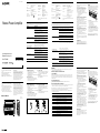
Dimensions / Dimensões
Unit: mm
Unidade: mm
234
252
309
55
376
Specifications
Circuit system OTL (output transformerless)
circuit
Pulse power supply
Inputs RCA pin jacks
Input level adjustment range
0.3 – 6 V (RCA pin jacks)
Outputs Speaker terminals
Speaker impedance 2 – 8 Ω (stereo)
4 – 8 Ω (when used as a bridging
amplifier)
Power output 90 W RMS × 4 (4 Ω, 1 kHz, 10 %
THD, 14.4 V)
Frequency response 5 Hz – 50 kHz (
dB)
Harmonic distortion 0.05 % or less (at 1 kHz, 4 Ω)
Low-pass filter 80 Hz, 18 dB/oct
High-pass filter 80 Hz, 12 dB/oct
Power requirements 12 V DC car battery
(negative ground)
Power supply voltage 10.5 – 16 V
Current drain at rated output: 31 A
(4 Ω, 60 W × 4)
Remote input: 1 mA
Dimensions Approx. 376 × 55 × 252 mm
(w/h/d) not incl. projecting parts
and controls
Mass Approx. 3.0 kg not incl. accessories
Supplied accessories Mounting screws (4)
Protection cap (1)
Design and specifications are subject to change
without notice.
Troubleshooting Guide
The following checklist will assist in the correction of most problems which you may encounter with your unit.
Before going through the checklist below, refer to the connection and operating procedures.
Problem Cause/Solution
The POWER/PROTECTOR indicator
does not light up.
The fuse is blown. Replace the fuse with a new one.
The ground wire is not securely connected.
Fasten the ground wire securely to a metal point of the car.
The voltage going into the remote terminal is too low.
The connected car audio unit is not turned on.
Turn on the car audio unit.
The system employs too many amplifiers.
Use a relay.
Check the battery voltage (10.5 – 16 V).
The POWER/PROTECTOR indicator will
change from green to red.
Turn off the power switch. The speaker outputs are shorted.
Rectify the cause of the short.
Turn off the power switch. Make sure the speaker cord and ground wire are
securely connected.
The unit becomes abnormally hot.
The unit heats up abnormally.
Use speakers with suitable impedance.
2 – 8 Ω (stereo), 4 – 8 Ω (when used as a bridging amplifier).
Make sure to place the unit in a well ventilated location.
The thermal protector is activated. Reduce the volume.
The sound is interrupted.
Alternator noise is heard.
The power connecting wires are installed too close to the RCA pin cords.
Keep the wires away from the cords.
The ground wire is not securely connected.
Fasten the ground wire securely to a metal point of the car.
Negative speaker wires are touching the car chassis.
Keep the wires away from the car chassis.
The sound is muffled.
The LPF switch is set to the “OFF” position.
When connecting the full range speaker, set to “OFF” position.
The FILTER select switch is set to the “OFF” position.
When connecting the full range speaker, set to “OFF” or “HP” position.
The sound is too low.
The LEVEL adjustment control is not appropriate. Turn the LEVEL adjustment
control in the clockwise direction.
Precauções
Este aparelho foi concebido para funcionar apenas
com CC de 12 V aterramento negativo.
Utilize alto-falantes com uma impedância de 2 a 8 Ω
(4 a 8 Ω quando utilizado como amplificador em
ponte).
Não ligue alto-falantes ativos (com amplificação)
aos terminais dos alto-falantes do aparelho. Se o
fizer, pode provocar danos nos alto-falantes ativos.
Evite instalar o aparelho em áreas:
— em que esteja exposto a altas temperaturas
como, por exemplo, à incidência direta dos raios
solares ou ao ar quente proveniente do
aquecedor
— em que esteja exposto à chuva ou umidade
— em que esteja exposto ao pó ou sujeira.
Se o automóvel estiver estacionado ao sol e a
temperatura no seu interior subir
consideravelmente, deixe o aparelho esfriar antes de
utilizá-lo.
Quando instalar o aparelho horizontalmente, não
tape a grelha de ventilação com o tapete, etc.
Se colocar o aparelho muito perto da unidade de
som ou da antena, podem ocorrer interferências. Se
isso acontecer, afaste o amplificador da unidade de
som ou da antena do automóvel.
Se o aparelho não estiver recebendo corrente,
verifique as conexões.
Este amplificador de potência possui um circuito de
proteção* que protege os transístores e os alto-
falantes, se o amplificador funcionar mal. Não teste
os circuitos de proteção tapando as aberturas de
resfriamento ou ligando-lhe cargas inadequadas.
Não utilize o aparelho com a bateria fraca pois, para
que funcione em condições ótimas, tem de existir
uma boa alimentação de corrente.
Por razões de segurança, mantenha o volume da
unidade de som a um nível moderado para poder
ouvir os sons do exterior.
Substituir o fusível
Se o fusível fundir, verifique as ligações de corrente e
substitua os dois fusíveis. Se, depois de o ter
substituído, o fusível voltar a fundir, pode existir um
defeito interno. Nesse caso, consulte o representante
Sony mais próximo.
Aviso
Quando substituir o fusível, verifique se está
utilizando um fusível com a amperagem idêntica à
indicada no fusível que retirou. Nunca utilize um
fusível com uma amperagem superior à do aparelho
porque pode provocar um defeito.
* Circuito de proteção
Este amplificador está equipado com um circuito de
proteção que funciona nas seguintes situações:
— se houver sobreaquecimento do aparelho
— se for gerada corrente CC
— se ocorrer um curto-circuito nos terminais dos
alto-falantes.
A cor do indicador POWER/PROTECTOR muda de verde
para vermelho e o aparelho desliga-se.
Se isto acontecer, desligue o equipamento, retire a cassete
ou o disco e verifique a causa do defeito. Se houver
sobreaquecimento do aparelho, aguarde
até que este esfrie antes de voltar a utilizá-lo.
Se tiver dúvidas ou problemas referentes ao aparelho
que não se encontrem neste manual, consulte o
representante Sony mais próximo.
Especificações
Sistema do circuito Circuito OTL (saída sem
transformador)
Fornecimento de corrente por
impulsos
Entradas tomadas de pinos RCA
Margem de regulação do nível de entrada
0,3 – 6 V (tomadas de pinos RCA)
Saídas Terminais dos alto-falantes
Impedância do alto-falante
2 – 8 Ω (estéreo)
4 – 8 Ω (quando utilizado como
amplificador em ponte)
Potência de saída 90 W RMS × 4 (4 Ω, 1 kHz, 10 %
THD, 14,4 V)
Resposta em frequência 5 Hz bis 50 kHz (
dB)
Distorção harmônica máx. 0,05 % ou menos (a 1 kHz,
4 Ω)
Filtro passa-baixo 80 Hz, 18 dB/oct
Filtro passa-alto 80 Hz, 12 dB/oct
Requisitos de corrente Bateria de automóvel de 12 V CC
(aterramento negativo)
Tensão de corrente 10,5 – 16 V
Corrente com saída nominal: 31 A
(4 Ω, 60 W × 4)
Entrada para controle remoto: 1 mA
Dimensões Aprox. 376 × 55 × 252 mm (l/a/p)
não incluindo controles e peças
salientes
Peso Aprox. 3,0 kg acessórios não
incluídos
Acessórios fornecidos Parafusos de montagem (4)
Capa de proteção (1)
Design e especificações sujeitos a alterações sem aviso
prévio.
Guia de resolução de problemas
A lista de verificação apresentada abaixo destina-se a ajudá-lo a solucionar a maioria dos problemas que possam surgir.
Antes de ler a lista de verificação apresentada abaixo, verifique as conexões e as operações de funcionamento.
Problema Causa/Solução
O indicador POWER/PROTECTOR não
acende.
O fusível está queimado. Substitua o fusível por um novo.
O fio terra não está bem conectado.
Conecte-o a um ponto metálico do automóvel.
A tensão que passa para o terminal remoto é muito baixa.
A unidade de som não está ligada.
Ligue-a.
O sistema está utilizando muitos amplificadores.
Utilize um relé.
Verifique a tensão da bateria (10,5 – 16 V).
O indicador POWER/PROTECTOR muda
de verde para vermelho.
Desligue o equipamento. Os alto-falantes estão em curto-circuito.
Corrija a causa do curto-circuito.
Desligue o equipamento. Verifique se o cabo do alto-falante e o fio terra estão
conectados de forma segura.
O aparelho aquece muito.
O aparelho aquece de forma anormal.
Utilize alto-falantes com a impedância adequada.
2 – 8 Ω (estéreo), 4 – 8 Ω (quando utilizado como amplificador em ponte)
Verifique se o instalou em um local bem ventilado.
O protetor térmico está ativado. Reduza o volume.
O som tem interrupções.
Ouve-se o ruído do alternador.
Os cabos de ligação à corrente estão instalados muito perto dos cabos de pinos
RCA.
Afaste os cabos uns dos outros.
O fio terra não está conectado de forma segura.
Ligue-o a um ponto metálico do automóvel.
Os fios negativos dos alto-falantes estão tocando no chassis do automóvel.
Afaste-os do chassis.
O som está abafado.
O interruptor LPF está definido para a posição “OFF”.
Ao conectar o alto-falante de gama total, coloque-o na posição “OFF”.
O interruptor seletor FILTER está definido para a posição “OFF”.
Ao conectar o alto-falante de gama total, coloque-o na posição “OFF” ou “HP”.
O volume do som está muito baixo.
O controle de regulação LEVEL não é adequado. Rode o controle de regulação de
LEVEL no sentido horário.
Location and Function of Controls
POWER/PROTECTOR indicator
Lights up in green during operation.
When the PROTECTOR is activated the indicator
will change from green to red.
When the PROTECTOR is activated refer to the
Troubleshooting Guide.
LEVEL adjustment control
The input level can be adjusted with this control.
Turn it in the clockwise direction when the output
level of the car audio unit seems low.
FILTER select switch
When the switch is in the LP position,the filter is set
to low-pass (80 Hz). When the switch is in the HP
position, the filter is set to high-pass (80 Hz).
LPF switch
When the LPF switch is set to ON, the Low-pass
filter (80 Hz) is effective.
Localização e funções dos controles
Indicador POWER/PROTECTOR
Acende-se com uma luz verde durante o
funcionamento.
Se PROTECTOR estiver ativado, o indicador muda
de verde para vermelho.
Se PROTECTOR estiver ativado, consulte o Guia de
resolução de problemas.
Controle de regulação de LEVEL
Este controle serve para regular o nível de entrada.
Gire no sentido horário se achar que o nível de
saída de áudio da unidade de som está baixo.
Interruptor selector de FILTER
Quando o interruptor está na posição LP, o filtro é
definido para passa-baixo (80 Hz). Quando o
interruptor está na posição HP, o filtro é definido
para passa-alto (80 Hz).
Interruptor LPF
Se o interruptor LPF estiver na posição ON, o filtro
passa-baixo (80 Hz) está ativado.
ADVERTÊNCIA
Evite o uso prolongado do aparelho com volume alto (potência superior a 85 decibéis), pois isto poderá
prejudicar a sua audição (Lei Federal No 11.291/06).
Recomendações Importantes sobre o Nível de Volume
Caro(a) consumidor(a)
Maximize o prazer de ouvir a música com este aparelho lendo estas recomendações que ensinam você a tirar o
máximo proveito do aparelho quando reproduzir um som a um nível seguro. Um nível que permite que o som
seja alto e claro, sem distorção e sem causar desconforto e, o mais importante, de uma forma que proteja a sua
sensibilidade auditiva.
Para estabelecer um nível seguro:
Ajuste o controle de volume a um nível baixo.
Aumente lentamente o som até poder ouvi-lo confortavelmente e claramente, sem distorções.
Uma vez estabelecido um nível de som confortável:
Ajuste o controle de volume e deixe-o nesta posição. O minuto gasto para fazer este ajuste agora protegerá a sua
audição no futuro. Afinal de contas, nós queremos que você ouça durante toda a vida.
Usando sabiamente o seu novo equipamento de som proporcionará a você uma vida toda de entretenimento e
prazer. A Sony recomenda que você evite a exposição prolongada a ruídos muito altos.
A seguir, incluímos uma tabela com os níveis de intensidade sonora em decibéis e os exemplos de situações
correspondentes para a sua referência.
Nível de Decibéis Exemplos
30 Biblioteca silenciosa, sussurros leves.
40 Sala de estar, refrigerador, quarto longe do trânsito.
50 Trânsito leve, conversação normal, escritório silencioso.
60 Ar condicionado a uma distância de 6 m, máquina de costura.
70 Aspirador de pó, secador de cabelo, restaurante ruidoso.
80 Tráfego médio de cidade, coletor de lixo, alarme de despertador a uma distância
de 60 cm.
OS RUÍDOS ABAIXO PODEM SER PERIGOSOS EM CASO DE EXPOSIÇÃO CONSTANTE
90 Metrô, motocicleta, tráfego de caminhão, cortador de grama.
100 Caminhão de lixo, serra elétrica, furadeira pneumática.
120 Show de banda de rock em frente às caixas acústicas, trovão.
140 Tiro de arma de fogo, avião a jato.
180 Lançamento de foguete.
Informação cedida pela Deafness Research Foundation, por cortesia.

XM-GTX6041_BR [GB/PT] 4-300-771-31(1)
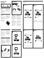
Power Connection Wires (not supplied)
Cabos de conexão à corrente (não fornecidos)
to a metal point of the car
a um ponto metálico do
automóvel
Fuse (50 A)
Fusível (50 A)
+12V car battery
Bateria do automóvel de +12V
Car audio unit
Unidade de som
Remote output*
1
Saída para
controle
remoto*
1
(REM)
less than 450 mm
inferior a 450 mm
*
2
*
1
If you have the factory original or some other car audio unit without a remote output for the amplifier, connect the
remote input terminal (REMOTE) to the accessory power supply.
*
1
Se tiver a unidade de som original fornecida de fábrica ou outro sistema de som para automóvel sem uma saída para
controle remoto no amplificador, conecte o terminal de entrada para controle remoto (REMOTE) à fonte de alimentação
para acessórios.
Line Input Connection
Conexão de entrada de linha
Line Input Connection
Conexão de entrada de linha
Input Connections / Conexões de entrada
4-Speaker System
Sistema de 4 alto-falantes
3-Speaker System
Sistema de 3 alto-falantes
Speaker Connections
Turn on or off the LPF and HPF switch at the unit rear as illustrated below.
Conexões dos alto-falantes
Ligue ou desligue o interruptor LPF e HPF na parte traseira do aparelho conforme ilustrado abaixo.
Connections / Conexões
Parts for Installation and Connections /
Peças para instalação e conexões
ø 5 × 15 mm
(× 4)
Installation
Before Installation
Mount the unit either inside the trunk or under a
seat.
Choose the mounting location carefully so the unit
will not interfere with the normal movements of the
driver and it will not be exposed to direct sunlight
or hot air from the heater.
Do not install the unit under the floor carpet, where
the heat dissipation from the unit will be
considerably impaired.
First, place the unit where you plan to install it, and
mark the positions of the 4 screw holes on the
mounting board (not supplied). Then drill a 3 mm
pilot hole at each mark and mount the unit onto the
board with the supplied mounting screws. The
mounting screws are all 15 mm long, so make sure
that the mounting board is thicker than
15 mm.
Instalação
Antes de fazer a instalação
Monte o aparelho dentro da mala ou por baixo do
banco.
Escolha cuidadosamente o local de montagem de
modo que o aparelho não interfira com os
movimentos normais do condutor e não fique
exposto à incidência direta dos raios solares nem ao
ar quente proveniente do sistema de aquecimento.
Não instale o aparelho por baixo do tapete do carro
porque impedirá a dissipação de calor do aparelho.
Em primeiro lugar, coloque o aparelho no local onde
pretende instalá-lo e marque as posições dos 4 furos
para os parafusos na placa de montagem (não
fornecida). Depois, faça um furo de 3 mm em cada
marca e monte o aparelho na placa, utilizando os
parafusos de montagem fornecidos. Como os
parafusos de montagem têm 15 mm de comprimento,
deve-se verificar se a placa de montagem tem uma
espessura superior a 15 mm.
Mount the unit as illustrated.
Monte o aparelho como mostra a figura.
Make the terminal connections as illustrated below.
Conecte os terminais como se mostra na figura abaixo.
Pass the wires through the cap, connect the wires, then cover the terminals with the cap.
Note
When you tighten the screw, be careful not to apply too much torque* as doing so may damage the screw.
* The torque value should be less than 1 N•m.
Passe os fios pela capa de proteção, conecte-os e depois tape os terminais com a capa de proteção.
Nota
Aperte bem o parafuso, mas não com muita força* para evitar danificá-lo.
* O valor da força aplicada deve ser inferior a 1 N•m.
Rear
Traseira
Front
Frontal
Car audio unit
Unidade de som
LINE OUT
LINE OUT
Notes
In this system, the volume of the subwoofer will be
controlled by the car audio unit fader control.
In this system, the output signals to the subwoofer will
be the combination of both the REAR L and R INPUT
jacks’ signals.
Front speaker (min. 2 Ω)
Alto-falantes frontais (mín. 2 Ω)
Rear speaker (min. 2 Ω)
Alto-falantes traseiros (min. 2 Ω)
Left
Esquerdo
Right
Direito
Left
Esquerdo
Right
Direito
Subwoofer (min. 4 Ω)
Subwoofer (min. 4 Ω)
Full range speakers (min. 2 Ω)
Alto-falantes de gama total (min. 2 Ω)
Left
Esquerdo
Right
Direito
Cautions
Before making any connections, disconnect the
ground terminal of the car battery to avoid short
circuits.
Be sure to use speakers with an adequate power
rating. If you use small capacity speakers, they may
be damaged.
This is a Phase-Inverted Amplifier.
Do not connect the terminal of the speaker
system to the car chassis, and do not connect the
terminal of the right speaker with that of the left
speaker.
Install the input and output cords away from the
power supply wire as running them close together
can generate some interference noise.
This unit is a high powered amplifier. Therefore, it
may not perform to its full potential if used with the
speaker cords supplied with the car.
If your car is equipped with a computer system for
navigation or some other purpose, do not remove
the ground wire from the car battery. If you
disconnect the wire, the computer memory may be
erased. To avoid short circuits when making
connections, disconnect the +12V power supply
wire until all the other wires have been connected.
Cuidado
Antes de fazer qualquer conexão, desligue o
terminal de aterramento da bateria do automóvel
para evitar curto-circuitos.
Verifique se os alto-falantes utilizados têm uma
potência nominal adequada. Se utilizar alto-falantes
de baixa capacidade, pode danificá-los.
Este amplificador é um amplificador de fase invertida.
Não ligue o terminal do sistema de alto-falantes
ao chassis do automóvel nem o terminal do alto-
falante direito ao terminal do alto-falante esquerdo.
Instale os cabos de entrada e de saída longe do cabo
de alimentação de corrente porque se estiverem
muito perto podem gerar interferências.
Este aparelho é um amplificador de grande
potência. Como tal, você pode não conseguir
utilizá-lo com a potência máxima se usar os cabos
para alto-falantes fornecidos com o automóvel.
Se o automóvel estiver equipado com um
computador de bordo para navegação, não retire o
fio terra da bateria do automóvel. Se desligar o fio, a
memória do computador será apagada. Para evitar
curto-circuitos, quando o fizer, conecte o cabo de
conexão à corrente de +12V somente depois de
conectar todos os outros cabos.
Notes on the power supply
Connect the +12V power supply wire only after all the other
wires have been connected.
Be sure to connect the ground wire of the unit securely
to a metal point of the car. A loose connection may
cause a malfunction of the amplifier.
Be sure to connect the remote control wire of the car audio
unit to the remote terminal.
When using a car audio unit without a remote output on the
amplifier, connect the remote input terminal (REMOTE) to
the accessory power supply.
Use a power supply wire with a fuse attached (50 A).
All power wires connected to the positive battery post
should be fused within 450 mm of the battery post, and
before they pass through any metal.
Make sure that the vehicle’s battery wires connected to the
vehicle (ground to chassis)*
2
are of a wire gauge at least
equal to that of the main power wire connected from the
battery to the amplifier.
During full-power operation, a current of more than 50 A
will run through the system. Therefore, make sure that the
wires to be connected to the +12V and GND terminals of
this unit are at least 10-Gauge (AWG-10) or have a sectional
area of more than 5 mm
2
.
Notas sobre o fornecimento de corrente
Conecte o cabo de conexão à corrente de +12V somente
depois de conectar todos os outros cabos.
Conecte o fio terra do aparelho a um ponto metálico do
automóvel. Uma conexão mal feita pode danificar o
amplificador.
Verifique se conectou o cabo do controle remoto da unidade
de som ao terminal para controle remoto.
Quando utilizar uma unidade de som sem saída para
controle remoto no amplificador, conecte o terminal de
entrada para controle remoto (REMOTE) à fonte de
alimentação para acessórios.
Utilize um cabo de conexão à corrente com um fusível
incorporado (50 A)
Todos os cabos elétricos conectados ao borne positivo da
bateria devem ter um fusível a uma distância de 450 mm do
borne da bateria e antes de passarem por qualquer parte
metálica.
Verifique se os cabos da bateria conectados ao automóvel
(aterramento negativo)*
2
têm uma medida pelo menos
igual à do cabo principal que conecta a bateria ao
amplificador.
Durante o funcionamento com potência total, o sistema é
percorrido por uma corrente superior a 50 A. Assim, verifique
se os cabos que vai conectar aos terminais +12V e GND
deste aparelho têm um calibre superior a 10 (AWG-10) ou
uma seção superior a 5 mm
2
.
Subwoofer (min. 2 Ω)
Subwoofer (min. 2 Ω)
Full range speakers (min. 2 Ω)
Alto-falantes de gama total (min. 2 Ω)
Left
Esquerdo
Right
Direito
Left
Esquerdo
Right
Direito
2-Way System
Sistema de 2 vias
Right
Direito
Left
Esquerdo
Car audio unit
Unidade de som
LINE OUT
Note
In this system, the volume of the subwoofer will be controlled by the car audio unit fader control.
Nota
Neste sistema, o volume do subwoofer será controlado pelo controle de fader da unidade de som.
2-Speaker System
Sistema de 2 alto-falantes
Subwoofer (min. 4 Ω)
Subwoofer (min. 4 Ω)
Right
Direito
Left
Esquerdo
Subwoofer (min. 4 Ω)
Subwoofer (min. 4 Ω)
Notas
Neste sistema, o volume do subwoofer será controlado
pelo controle de fader da unidade de som do
automóvel.
Neste sistema, os sinais de saída para o subwoofer serão
a combinação dos sinais das tomadas REAR L e R INPUT.
-
 1
1
-
 2
2


Sony XM-GTX6041 Manual do proprietário
- Categoria
- Alto-falantes do carro
- Tipo
- Manual do proprietário
em outras línguas
- English: Sony XM-GTX6041 Owner's manual
Artigos relacionados
-
Sony XM-604M Manual do usuário
-
Sony XM-GTX6040 Manual do usuário
-
Sony XM-ZR6022 Manual do usuário
-
Sony XM-ZZR3301 Instruções de operação
-
Sony XM-N1004 Instruções de operação
-
Sony XM-N502 Instruções de operação
-
Sony XM-ZR602 Instruções de operação
-
-
Sony XM-S400D Manual do proprietário
-