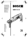
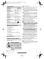
Bosch GBM 16-2 E Operating Instructions Manual
- Categoria
- Exercícios de força
- Tipo
- Operating Instructions Manual

EURO • Printed in Germany • BA 3 609 929 468 • GBM 16-2 • Titel (Vorderseite) • OSW 02.05
Bedienungsanleitung
Operating Instructions
Instructions d’emploi
Instrucciones de servicio
Manual de instruções
Istruzioni d’uso
Gebruiksaanwijzing
Betjeningsvejledning
Bruksanvisning
Brukerveiledningen
Käyttöohje
Oδηγία øειρισµïύ
Kullanım kılavuzu
Deutsch
English
Français
Español
Português
Italiano
Nederlands
Dansk
Svenska
Norsk
Suomi
Eλληνικά
Türkçe
GBM 16-2 E
3 609 929 468.book Seite 1 Donnerstag, 2. Mai 2002 10:51 10

EURO • Printed in Germany • BA 3 609 929 468 • GBM 16-2 • U2 • OSW 02.05
2 • 3 609 929 468 • 02.05
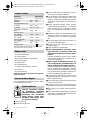
2 608 180 003
(BS 35)
2 608 180 004
(BS 45)
2 608 030 053
(MS 65)
2 608 030 054
(MS 75)
2 608 030 055
(MS 80)
3 609 929 468.book Seite 2 Donnerstag, 2. Mai 2002 10:51 10

EURO • Printed in Germany • BA 3 609 929 468 • GBM 16-2 • U3 • OSW 02.05
3 • 3 609 929 468 • 02.05
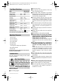
GBM 16-2 E
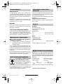
1
2
3
4
5
6
7
8
x
x
A
7
➊➋
B
9
3 609 929 468.book Seite 5 Donnerstag, 2. Mai 2002 10:51 10

EURO • Printed in Germany • BA 3 609 929 468 • GBM 16-2 • D • OSW 02.05
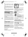
Deutsch - 1
1 Zahnkranzbohrfutter
2 Gangwahlschalter
3 Feststelltaste
4 Ein-/Ausschalter
5 Bohrfutterschlüssel
6 Tiefenanschlag
7 Flügelschraube für
Tiefenanschlagverstellung
8 Zusatzgriff
9 Innensechskantschlüssel
Abgebildetes oder beschriebenes Zubehör gehört
teilweise nicht zum Lieferumfang.
Das Gerät ist bestimmt zum Bohren in Holz, Me-
tall, Keramik und Kunststoff.
Gefahrloses Arbeiten mit dem
Gerät ist nur möglich, wenn Sie
die Bedienungsanleitung und
die Sicherheitshinweise voll-
ständig lesen und die darin ent-
haltenen Anweisungen strikt be-
folgen. Zusätzlich müssen die allgemeinen
Sicherheitshinweise im beigefügten Heft be-
folgt werden.
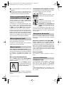
■ Schutzbrille tragen.
■ Festes Schuhwerk tragen.
■ Bei langen Haaren Haarschutz tragen. Nur mit
enganliegender Kleidung arbeiten.
■ Wird bei der Arbeit das Netzkabel beschädigt
oder durchtrennt, Kabel nicht berühren, son-
dern sofort den Netzstecker ziehen. Gerät nie-
mals mit beschädigtem Kabel benutzen.
■ Geräte, die im Freien verwendet werden, über
einen Fehlerstrom-Schutzschalter (FI-) mit
maximal 30 mA Auslösestrom anschließen.
Nur ein für den Außenbereich zugelassenes
Verlängerungskabel verwenden.
■ Das Gerät darf nur an ein ordnungsgemäß ge-
erdetes Stromnetz angeschlossen werden.
Steckdose und Verlängerungskabel müssen
einen funktionsfähigen Schutzleiter besitzen.
■ Stecker nur bei ausgeschaltetem Gerät in die
Steckdose einstecken.
■ Kabel immer nach hinten vom Gerät wegfüh-
ren.
■ Beim Bohren Zusatzgriff 8 verwenden.
■ Das Elektrowerkzeug nur an isolierten
Handgriffen anfassen, wenn das Einsatz-
werkzeug eine verborgene Leitung oder
das eigene Netzkabel treffen kann.
Kontakt mit einer spannungsführenden Lei-
tung kann Metallteile des Gerätes unter Span-
nung setzen und zu einem elektrischen Schlag
führen.
■ Verwenden Sie geeignete Suchgeräte, um
verborgene Versorgungsleitungen aufzu-
spüren, oder ziehen Sie die örtliche Versor-
gungsgesellschaft hinzu.
Kontakt mit Elektroleitungen kann zu Feuer
und elektrischem Schlag führen. Beschä-
digung einer Gasleitung kann zur Explosion
führen. Eindringen in eine Wasserleitung ver-
ursacht Sachbeschädigung oder kann einen
elektrischen Schlag verursachen.
■ Blockieren des Bohrwerkzeugs führt zu ruck-
artiger Reaktionskraft des Gerätes. In diesem
Fall Gerät sofort ausschalten.
■ Beim Arbeiten das Gerät immer fest mit beiden
Händen halten und für einen sicheren Stand
sorgen.
■ Das Gerät vor dem Ablegen immer ausschal-
ten und warten bis das Gerät zum Stillstand
gekommen ist.
■ Niemals Kindern die Benutzung des Gerätes
gestatten.
■ Bosch kann nur dann eine einwandfreie Funk-
tion des Gerätes zusichern, wenn das für die-
ses Gerät vorgesehene Original-Zubehör ver-
wendet wird.
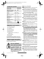
Gerätekennwerte
Bohrmaschine GBM 16-2 E
Bestellnummer 0 601 120 6..
Nennaufnahme [W] 900
Abgabeleistung [W] 475
Leerlaufdrehzahl
1. Gang [min
-1
] 520
2. Gang [min
-1
] 1 200
Bohrfutterspannbereich
max.
[mm] 16
Bohr-Ø Stahl
1./2. Gang
[mm] 16/8
Bohr-Ø Holz
1./2. Gang
[mm] 40/20
Bohr-Ø Aluminium
1./2. Gang
[mm] 20/13
Gewicht ca. [kg] 3,6
Schutzklasse / II
Bitte die Bestellnummer Ihrer Maschine beachten. Die
Handelsbezeichnungen einzelner Maschinen können
variieren.
Geräteelemente
Bestimmungsgemäßer Gebrauch
Zu Ihrer Sicherheit
3 609 929 468.book Seite 1 Donnerstag, 2. Mai 2002 10:51 10
4 • 3 609 929 468 • TMS • 18.04.02

EURO • Printed in Germany • BA 3 609 929 468 • GBM 16-2 • D • OSW 02.05
Deutsch - 2
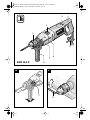
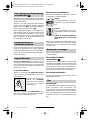
Je nach Anwendung kann der Zusatzgriff in jeder
beliebigen Winkellage am Spindelhals montiert
werden.
Zum Verstellen des Zusatzgriffes, unteres Griff-
stück gegen den Uhrzeigersinn drehen (
➊) und
in der gewünschten Stellung wieder festzie-
hen (
➋).
Mit dem Tiefenanschlag 6 kann die Bohrtiefe ein-
gestellt werden. Die Flügelschraube 7 lösen und
Tiefenanschlag parallel bis auf Höhe der Bohrer-
spitze herausziehen. An der Skala (Pfeil) den ab-
gelesenen Skalenwert abzüglich der gewünsch-
ten Bohrtiefe X einstellen.
Das Bohrfutter öffnen, bis das Werkzeug einge-
setzt werden kann. Das Werkzeug einsetzen.
Mit dem Bohrfutterschlüssel 5 gleichmäßig in al-
len drei Bohrungen spannen.
Netzspannung beachten: Die Spannung der
Stromquelle muss mit den Angaben auf dem
Typschild des Gerätes übereinstimmen. Mit
230 V gekennzeichnete Geräte können auch an
220 V betrieben werden.
Ein-/Ausschalten
Zur Inbetriebnahme des Gerätes den Ein-/Aus-
schalter 4 drücken und gedrückt halten.
Zum Feststellen den Ein-/
Ausschalter 4 drücken und
die Feststelltaste 3 nach
oben schieben.
Zum Ausschalten des Gerätes den Ein-/Aus-
schalter 4 loslassen bzw. drücken und loslassen.
Mechanische Gangwahl
Mit dem Gangwahlschalter 2 können zwei Dreh-
zahlbereiche vorgewählt werden:
Gang I:
Niedriger Drehzahlbereich; zum Ar-
beiten mit großem Bohrdurchmes-
ser.
Gang II:
Hoher Drehzahlbereich; zum Arbei-
ten mit kleinem Bohrdurchmesser.
Den Gangwahlschalter 2 nur bei
Stillstand des Gerätes betätigen!
Lässt sich der Gangwahlschalter 2 bei Stillstand
nicht bis zum Anschlag drehen, die Antriebsspin-
del mit dem Bohrer etwas drehen.
Den Innensechskantschlüssel mit dem kurzen
Schaft voran in das Bohrfutter einspannen.
Bohrfutter lösen (siehe Bild )
Die Maschine auf eine standfeste Unterlage
(z. B. Werkbank) legen. Die Maschine festhalten
und das Bohrfutter wie eine Schraube durch
Linksdrehen lösen. Ein festsitzendes Bohrfutter
wird durch einen Schlag auf den langen Schaft
des Innensechskantschlüssels 9 gelöst.
Bohrfutter festziehen
Die Montage des Bohrfutters erfolgt in umgekehr-
ter Reihenfolge.
Bohrer schärfen
Beim Bohren in Metall nur einwandfreie ge-
schärfte HSS-Bohrer (HSS = Hochleistungs-
Schnell-Schnittstahl) verwenden. Entsprechende
Qualität garantiert das Bosch-Zubehör-Pro-
gramm.
Mit dem Bohrerschärfgerät (siehe Zubehör) kön-
nen Sie Spiralbohrer von 3,5–10 mm mühelos
schärfen.
Bohrständer
Für besonders präzise Arbeiten empfiehlt es
sich, einen Bohrständer (siehe Zubehör) zu ver-
wenden.
Maschinenschraubstock
Der als Zubehör erhältliche Maschinenschraub-
stock ermöglicht sicheres Festspannen von
Werkstücken. Dies verhindert ein Verdrehen des
Werkstückes und dadurch entstehende Unfälle.
Zusatzgriff/Tiefenanschlag
(siehe Bild )
Werkzeug einsetzen
Inbetriebnahme
A
3
4
Bohrfutter wechseln
Tipps
B
3 609 929 468.book Seite 2 Donnerstag, 2. Mai 2002 10:51 10
5 • 3 609 929 468 • TMS • 18.04.02

EURO • Printed in Germany • BA 3 609 929 468 • GBM 16-2 • D • OSW 02.05
Deutsch - 3
■ Vor allen Arbeiten am Gerät Netzstecker
ziehen.
☞
Gerät und Lüftungsschlitze stets sauber
halten, um gut und sicher zu arbeiten.
Sollte das Gerät trotz sorgfältiger Herstellungs-
und Prüfverfahren einmal ausfallen, ist die Repa-
ratur von einer autorisierten Kundendienststelle
für Bosch-Elektrowerkzeuge ausführen zu las-
sen.
Bei allen Rückfragen und Ersatzteilbestellungen
bitte unbedingt die 10-stellige Bestellnummer laut
Typenschild des Gerätes angeben.
Rohstoffrückgewinnung statt Müllentsorgung
Gerät, Zubehör und Verpackung sollten einer
umweltgerechten Wiederverwertung zugeführt
werden.
Diese Anleitung ist aus chlorfrei gefertigtem Re-
cycling-Papier hergestellt. Zum sortenreinen Re-
cycling sind Kunststoffteile gekennzeichnet.
In Deutschland sind nicht mehr gebrauchsfähige
Geräte zum Recycling beim Handel abzugeben
oder (ausreichend frankiert) direkt einzuschicken
an:
Recyclingzentrum Elektrowerkzeuge
Osteroder Landstraße 3
37589 Kalefeld
Messwerte ermittelt entsprechend EN 50 144.
Der A-bewertete Schalldruckpegel des Gerätes
beträgt typischerweise 83 dB (A).
Der Geräuschpegel beim Arbeiten kann
85 dB (A) überschreiten.
Gehörschutz tragen!
Die Hand-Arm-Vibration ist typischerweise niedri-
ger als 2,5 m/s
2
.
www.powertool-portal.de, das Internetportal
für Handwerker und Heimwerker
www.ewbc.de, der Informations-Pool für Hand-
werk und Ausbildung
Deutschland
Robert Bosch GmbH
Servicezentrum Elektrowerkzeuge
Zur Luhne 2
D-37589 Kalefeld
✆ Service:....................................... 01 80 - 3 35 54 99
Fax
............................................. +49 (0) 55 53 / 20 22 37
✆ Kundenberater:...................... 01 80 - 3 33 57 99
Österreich
ABE Service GmbH
Jochen-Rindt-Straße 1
A-1232 Wien
✆ Service:..................................... +43 (0)1 / 61 03 80
Fax
................................................. +43 (0)1 / 61 03 84 91
✆ Kundenberater:............. +43 (0)1 / 797 22 3066
E-Mail: [email protected]
Schweiz
Robert Bosch AG
Kundendienst Elektrowerkzeuge
Industriestrasse 31
CH-8112 Otelfingen
✆ Service:................................. +41 (0)1 / 8 47 16 16
✆ Kundenberater:...... Grüne Nr. 0 800 55 11 55
Wir erklären in alleiniger Verantwortung, dass
dieses Produkt mit den folgenden Normen oder
normativen Dokumenten übereinstimmt:
EN 50 144 gemäß den Bestimmungen der Richt-
linien 89/336/EWG, 98/37/EG.
Dr. Gerhard Felten Dr. Eckerhard Strötgen
Entwicklungsleiter Leiter Produktzulassung
Robert Bosch GmbH, Geschäftsbereich Elektrowerkzeuge
Änderungen vorbehalten
Wartung und Reinigung
Umweltschutz
Geräusch-/Vibrationsinformation
Service und Kundenberater
Konformitätserklärung
3 609 929 468.book Seite 3 Donnerstag, 2. Mai 2002 10:51 10
6 • 3 609 929 468 • TMS • 18.04.02

EURO • Printed in Germany • BA 3 609 929 468 • GBM 16-2 • GB • OSW 02.05
English - 1
1 Key chuck
2 Gear selector
3 Lock-on button
4 On/Off switch
5 Chuck key
6 Depth stop
7 Wing bolt for depth stop adjustment
8 Auxiliary handle
9 Allen key
Not all of the accessories illustrated or described are
included as standard delivery.
The drill is designed for drilling in wood, metal,
ceramic and plastic.
Working safely with this ma-
chine is possible only when the
operating and safety information
are read completely and the in-
structions contained therein are
strictly followed. In addition, the
general safety notes in the enclosed booklet
must be observed.
■ Wear safety goggles.
■ Wear sturdy shoes.
■ For long hair, wear hair protection. Work only
with closely fitting clothes.
■ If the mains cable is damaged or cut through
while working, do not touch the cable but im-
mediately pull the mains plug. Never use the
machine with a damaged cable.
■ Connect machines that are used in the open
via a residual current device (RCD) with an ac-
tuating current of 30 mA maximum. Use only
extension cables that are approved for outdoor
use.
■ The machine may be connected only to prop-
erly earthed mains. The socket and extension
cable must have a functional protective con-
ductor.
■ Insert the mains plug only when the machine is
switched off.
■ Always direct the cable to the rear away from
the machine.
■ When drilling use the auxiliary handle 8.
■ Hold the power tool only by the insulated
gripping surfaces, when performing an op-
eration where the cutting tool may run into
hidden wiring or its own cord.
Contact with a “live” wire will make exposed
metal parts of the tool “live” and shock the op-
erator.
■ Use appropriate detectors to determine if
utility lines are hidden in the work area or
call the local utility company for assist-
ance.
Contact with electric lines can lead to fire and
electric shock. Damaging a gas line can lead
to explosion. Penetrating a water line causes
property damage or may cause an electric
shock.
■ If the drilling tool jams, it will cause the power
tool to jolt. If this occurs switch the machine off
immediately.
■ When working with the machine, always hold it
firmly with both hands and provide for a secure
stance.
■ Always switch the machine off and wait until it
has come to a standstill before placing it down.
■ Never allow children to use the machine.
■ Bosch is only able to ensure perfect operation
of the machine if the original accessories in-
tended for it are used.
Tool Specifications
Drill GBM 16-2 E
Order number 0 601 120 6..
Rated power [W] 900
Output power [W] 475
No-load speed
1st gear [rpm] 520
2nd gear [rpm] 1 200
Chuck clamping
range max.
[mm] 16
Drilling dia., steel
1st/2nd gear
[mm] 16/8
Drilling dia., wood
1st/2nd gear
[mm] 40/20
Drilling dia., aluminium
1st/2nd gear
[mm] 20/13
Weight approx. [kg] 3.6
Protection class / II
Please observe the order number of your machine.
The trade names of the individual machines may vary.
Machine Elements
Intended Use
For Your Safety
3 609 929 468.book Seite 1 Donnerstag, 2. Mai 2002 10:51 10
7 • 3 609 929 468 • TMS • 18.04.02

EURO • Printed in Germany • BA 3 609 929 468 • GBM 16-2 • GB • OSW 02.05
English - 2
Depending on the application, the auxiliary han-
dle can be mounted to the spindle collar in any
position.
For adjustment of the auxiliary handle, turn the
bottom part of the handle in counterclockwise di-
rection (
➊) and retighten again in the required
position (
➋).
The drilling depth can be set with the depth
stop 6. Loosen wing bolt 7 and pull the depth stop
out until it is flush with the tip of the drill bit. On the
scale (arrow), subtract the required drilling
depth X from the scale value read and adjust.
Open the drill chuck until the tool can be inserted.
Insert the tool.
Clamp evenly in all three holes with the chuck
key 5.
Observe correct mains voltage: The voltage of
the power source must agree with the voltage
specified on the nameplate of the machine.
Equipment marked with 230 V can also be con-
nected to 220 V.
Switching On and Off
To start the machine, press the On/Off switch 4
and keep it depressed.
Lock the pushed On/Off
switch 4 by pushing the lock-
on button 3 upward.
To switch off the machine, release the On/Off
switch 4 or push and release it then.
Gear Selection, Mechanical
Two speed ranges can be pre-selected with the
gear selector 2:
1st gear:
Low speed range; for working with
large drilling diameter.
2nd gear:
Higher speed range; for working
with small drilling diameter.
Actuate the gear selector 2 only
when the machine is at a stand-
still!
If the gear selector 2 cannot be fully engaged at
standstill, lightly rotate the drive/drill spindle with
the drill bit by twisting the chuck.
Clamp the short end of an Allen key in the chuck.
Loosening the Drill Chuck
(see figure )
Place the machine on a firm surface (e. g., work-
bench). Hold the machine firmly and loosen the
drill chuck by turning to the left in the same way
as for a screw. Loosen a tightly sitting drill chuck
by giving the long shaft of the Allen key 9 a sharp
knock.
Tightening the Drill Chuck
The drill chuck is mounted in reverse order.
Sharpening Drill Bits
For drilling in metal, use only perfectly sharpened
HSS drills. The appropriate quality is guaranteed
by the Bosch accessories program.
Twist drills from 3.5–10 mm can easily be sharp-
ened with the drill sharpener (see accessories).
Bench Stand
We recommend the use of a bench stand (see
accessories) for work where greater precision is
particularly required.
Machine Vice
The machine vice can be obtained as an acces-
sory and clamps work pieces tightly for drilling.
This prevents the work piece from turning and
any accidents this would cause.
Auxiliary Handle/Depth Stop
(see figure )
Inserting the Tool
Initial Operation
A
3
4
Replacing the Drill Chuck
Tips
B
3 609 929 468.book Seite 2 Donnerstag, 2. Mai 2002 10:51 10
8 • 3 609 929 468 • TMS • 18.04.02

EURO • Printed in Germany • BA 3 609 929 468 • GBM 16-2 • GB • OSW 02.05
English - 3
■ Before any work on the machine itself, pull
the mains plug.
☞
For safe and proper working, always keep
the machine and the ventilation slots clean.
If the machine should fail despite the care taken
in manufacturing and testing procedures, repair
should be carried out by an after-sales service
centre for Bosch power tools.
In all correspondence and spare parts orders,
please always include the 10-digit order number
given on the nameplate of the machine.
WARNING! Important instructions for con-
necting a new 3-pin plug to the 2-wire cable.
The wires in the cable are coloured according to
the following code:
Do not
connect the blue or brown wire to the
earth terminal of the plug.
Important: If for any reason the moulded plug is
removed from the cable of this machine it must be
disposed of safely.
Recycle raw materials instead of
disposing as waste
The machine, accessories and
packaging should be sorted for en-
vironmental-friendly recycling.
These instructions are printed on recycled paper
manufactured without chlorine. The plastic com-
ponents are labelled for categorized recycling.
Measured values determined according to
EN 50 144.
Typically the A-weighted sound pressure level of
the product is 83 dB (A).
The noise level when working can exceed
85 dB (A).
Wear hearing protection!
The typical hand/arm vibration is below 2.5 m/s
2
.
Great Britain
Robert Bosch Ltd. (B.S.C.)
P.O. Box 98
Broadwater Park
North Orbital Road
Denham-Uxbridge
GB-Middlesex UB 9 5HJ
✆ Service............................ +44 (0)18 95 / 83 87 82
✆ Advice line.................... +44 (0)18 95 / 83 87 91
Fax
............................................. +44 (0)18 95 / 83 87 89
Ireland
Beaver Distribution Ltd.
Greenhills Road
IRL-Tallaght-Dublin 24
✆ Service................................... +353 (0)1 / 414 9400
Fax
.................................................... +353 (0)1 / 459 8030
Australia
Robert Bosch Australia L.t.d.
RBAU/SPT2
1555 Centre Road
P.O. Box 66 Clayton
AUS-3168 Clayton/Victoria
✆ ................................................ +61 (0)1 / 800 804 777
Fax
................................................ +61 (0)1 / 800 819 520
www.bosch.com.au
E-Mail: [email protected]
New Zealand
Robert Bosch Limited
14-16 Constellation Drive
Mairangi Bay
Auckland
New Zealand
✆ ..................................................... +64 (0)9 / 47 86 158
Fax
..................................................... +64 (0)9 / 47 82 914
We declare under our sole responsibility that this
product is in conformity with the following stand-
ards or standardization documents: EN 50 144
according to the provisions of the directives
89/336/EEC, 98/37/EC.
Dr. Gerhard Felten Dr. Eckerhard Strötgen
Senior Vice President Engineering Head of Product Certification
Robert Bosch GmbH, Geschäftsbereich Elektrowerkzeuge
Subject to change without notice
Maintenance and Cleaning
Environmental Protection
Noise/Vibration Information
strain relief
live = brown
neutral = blue
To be fitted
by qualified
professional only
Service and
Customer Assistance
Declaration of Conformity
3 609 929 468.book Seite 3 Donnerstag, 2. Mai 2002 10:51 10
9 • 3 609 929 468 • TMS • 18.04.02

EURO • Printed in Germany • BA 3 609 929 468 • GBM 16-2 • F • OSW 02.05
Français - 1
1 Mandrin à clé
2 Commutateur de vitesse
3 Bouton de blocage
4 Interrupteur Marche/Arrêt
5 Clé de mandrin
6 Butée de profondeur
7 Vis papillon pour le réglage de la butée de
profondeur
8 Poignée supplémentaire
9 Clé mâle pour vis à six pans creux
Les accessoires reproduits ou décrits ne sont pas
forcément fournis avec la machine.
L’appareil est conçu pour le perçage dans le bois,
le métal, la céramique et les matières plastiques.
Pour travailler sans risque avec
cet appareil, lire intégralement
au préalable les instructions
d’utilisation et les remarques
concernant la sécurité. Respec-
ter scrupuleusement les indica-
tions et les consignes qui y sont données.
Respecter en plus les indications générales
de sécurité se trouvant dans le cahier ci-joint.
■ Porter des lunettes de protection.
■ Mettre une paire de chaussures solides.
■ Les personnes portant les cheveux longs doi-
vent se munir d’un protège-cheveux. Ne tra-
vailler qu’avec des vêtements près du corps.
■ Si le câble d’alimentation électrique est en-
dommagé ou se rompt pendant le travail, ne
pas y toucher. Retirer immédiatement la fiche
du câble d’alimentation de la prise de courant.
Ne jamais utiliser un appareil dont le cordon
d’alimentation est endommagé.
■ Monter un disjoncteur différentiel (courant de
déclenchement : 30 mA max.) en amont des
appareils utilisés en plein air. N’utiliser qu’un
câble de rallonge électrique autorisé pour les
travaux à l’extérieur.
■ L’appareil ne doit être branché que sur un ré-
seau de courant électrique correctement relié
à la terre. La prise de courant ainsi que la ral-
longe électrique doivent être munies d’un con-
ducteur de protection en bon état.
■ Ne brancher l’appareil que si celui-ci est en po-
sition « Arrêt ».
■ Toujours ramener les câbles à l’arrière de l’ap-
pareil.
■ Pour effectuer des travaux de perçage, utiliser
la poignée supplémentaire 8.
■ Ne tenir l’outil électrique que par les poi-
gnées isolées lorsqu’il y a risque que l’outil
électrique puisse toucher une conduite ca-
chée ou son propre câble d’alimentation.
Le contact avec une conduite sous tension
peut mettre les parties métalliques de l’appa-
reil sous tension et provoquer ainsi un choc
électrique.
■ Utiliser des détecteurs appropriés afin de
déceler des conduites cachées ou consul-
ter les entreprises d’approvisionnement lo-
cales.
Un contact avec des conduites d’électricité
peut provoquer un incendie ou un choc électri-
que. Un endommagement d’une conduite de
gaz peut provoquer une explosion. La perfora-
tion d’une conduite d’eau provoque des dégâts
matériels et peut provoquer un choc électri-
que.
■ Le blocage de l’outil de perçage provoque de
fortes réactions au niveau de l’appareil. Dans
ce cas-là, arrêter immédiatement l’appareil.
■ Pendant le travail avec cet appareil, le tenir
toujours fermement avec les deux mains.
Adopter une position stable et sûre.
■ Avant de déposer l’appareil, toujours le mettre
hors fonctionnement et attendre l’arrêt total de
l’appareil.
Caractéristiques techniques
Perceuse GBM 16-2 E
Référence 0 601 120 6..
Puissance absorbée [W] 900
Puissance débitée [W] 475
Régime à vide
1ère vitesse [tr/min] 520
2ème vitesse [tr/min] 1 200
Fixation du mandrin de
perçage max.
[mm] 16
Ø perçage dans l’acier
1ère/2ème vitesse
[mm] 16/8
Ø perçage dans le bois
1ère/2ème vitesse
[mm] 40/20
Ø perçage dans l’alumi-
nium 1ère/2ème vitesse
[mm] 20/13
Poids env. [kg] 3,6
Classe de protection / II
Faire attention au numéro de référence de la machine.
Les désignations commerciales des différentes machines
peuvent varier.
Eléments de la machine
Utilisation conformément à la
destination de l’appareil
Pour votre sécurité
3 609 929 468.book Seite 1 Donnerstag, 2. Mai 2002 10:51 10
10 • 3 609 929 468 • TMS • 18.04.02

EURO • Printed in Germany • BA 3 609 929 468 • GBM 16-2 • F • OSW 02.05
Français - 2
■ Ne jamais permettre aux enfants d’utiliser cet
appareil.
■ Bosch ne peut garantir un fonctionnement im-
peccable que si les accessoires Bosch d’ori-
gine prévus pour cet appareil sont utilisés.
Suivant l’utilisation, la poignée supplémentaire
peut être montée dans n’importe quelle position
angulaire sur le collet de broche.
Pour déplacer la poignée supplémentaire, tour-
ner le manche de la poignée supplémentaire
dans le sens inverse des aiguilles d’une mon-
tre (
➊) et le resserrer (➋) une fois la poignée
supplémentaire mise dans la position désirée.
La butée de profondeur 6 permet de régler la pro-
fondeur de perçage. Pour cela, desserrer la vis
papillon 7 et tirer la butée de profondeur parallè-
lement jusqu’à la pointe du foret. Régler la valeur
relevée sur la graduation (flèche) après avoir dé-
duit la profondeur de perçage X souhaitée.
Ouvrir le mandrin de perçage de sorte que l’outil
puisse être monté. Monter l’outil.
A l’aide de la clé de mandrin 5, serrer de manière
régulière dans les trois alésages.
Tenir compte de la tension du secteur : La ten-
sion de la source de courant doit correspondre
aux indications figurant sur la plaque signalétique
de l’appareil. Les appareils fonctionnant sous
230 V peuvent également être exploités sous
220 V.
Mise en fonctionnement/Arrêt
Afin de mettre l’appareil en fonctionnement,
appuyer sur l’interrupteur Marche/Arrêt 4 et le
maintenir appuyé.
Afin de le bloquer, appuyer
sur l’interrupteur Marche/Ar-
rêt 4 et pousser vers le haut
le bouton de blocage 3.
Afin d’arrêter l’appareil, relâcher l’interrupteur
Marche/Arrêt 4 ou appuyer sur l’interrupteur et le
relâcher.
Commutation mécanique de la vitesse
Le commutateur de vitesse 2 permet de sélec-
tionner deux plages de vitesse de rotation :
Vitesse I :
Petites vitesses de rotation ; pour
diamètres de perçage importants.
Vitesse II :
Vitesses de rotation élevées ; pour
petits diamètres de perçage.
N’actionner le commutateur de
vitesse 2 qu’à l’arrêt total de l’ap-
pareil !
Au cas où le commutateur de vitesse 2 ne se lais-
serait pas tourner à fond, l’appareil étant à l’arrêt,
tourner légèrement la broche d’entraînement
muni du foret.
Serrer la clé mâle coudée pour vis à six pans
creux avec le côté le plus court dans le mandrin
de serrage.
Desserrer le mandrin (voir figure )
Déposer l’appareil sur un support rigide (par
exemple établi). Maintenir l’appareil et desserrer
le mandrin de perçage par un mouvement de ro-
tation vers la gauche exactement comme pour
une vis. Au cas où le mandrin de perçage serait
coincé, il suffit de donner un coup sur le bout long
de la clé mâle coudée pour vis à six pans creux 9
afin de le desserrer.
Serrer le mandrin
Pour monter le mandrin, procéder en sens in-
verse.
Affûtage des forets
Lors de perçages dans les métaux, n’utiliser que
des forets HSS en bon état et bien affûtés
(HSS = aciers super rapides). Le programme
d’accessoires Bosch garantit la qualité des fo-
rets.
Le dispositif d’affûtage (voir « accessoires ») per-
met un affûtage aisé des forets hélicoïdaux de
3,5–10 mm.
Poignée supplémentaire/Butée
de profondeur (voir figure )
Mise en place de l’outil
Mise en service
A
3
4
Changement du mandrin
Conseils d’utilisation
B
3 609 929 468.book Seite 2 Donnerstag, 2. Mai 2002 10:51 10
11 • 3 609 929 468 • TMS • 18.04.02

EURO • Printed in Germany • BA 3 609 929 468 • GBM 16-2 • F • OSW 02.05
Français - 3
Support de perçage
Lors de travaux nécessitant une grande préci-
sion, il est recommandé d’utiliser un support de
perçage (voir « accessoires »).
Etau
L’étau, disponible en tant qu’accessoire, permet
de serrer les pièces à travailler afin d’empêcher
un glissement de la pièce et de réduire ainsi les
risques d’accidents qui pourraient en résulter.
■ Avant toute intervention sur l’appareil pro-
prement dit, toujours retirer la fiche du câ-
ble d’alimentation de la prise de courant.
☞
Pour obtenir un travail sûr et satisfaisant,
nettoyer régulièrement l’appareil ainsi que
ses ouïes de refroidissement.
Si, malgré tous les soins apportés à la fabrication
et au contrôle de l’appareil, celui-ci devait avoir
un défaut, la réparation ne doit être confiée qu’à
une station de service après-vente agréée pour
outillage Bosch.
Pour toute demande de renseignements ou com-
mande de pièces de rechange, nous préciser im-
pérativement le numéro de référence à dix chif-
fres de la machine.
Récupération des matières pre-
mières plutôt qu’élimination des
déchets
Les machines, comme d’ailleurs
leurs accessoires et emballages,
doivent pouvoir suivre chacune une
voie de recyclage appropriée.
Ce manuel d’instructions a été fabriqué à partir
d’un papier recyclé blanchi en l’absence de
chlore. Nos pièces plastiques ont ainsi été mar-
quées en vue d’un recyclage sélectif des diffé-
rents matériaux.
Valeurs de mesure obtenues conformément à la
norme européenne 50 144.
La mesure réelle (A) du niveau sonore de l’outil
est de 83 dB (A).
Le niveau sonore en fonctionnement peut dépas-
ser 85 dB (A).
Munissez-vous d’une protection acoustique !
La vibration de l’avant-bras est en-dessous de
2,5 m/s
2
.
France
Information par Minitel 11
Nom : Bosch Outillage
Loc : Saint Ouen
Dépt : 93
Robert Bosch France S.A.
Service Après-vente/Outillage
B.P. 67-50, Rue Ardoin
F-93402 St. Ouen Cedex
✆ Service conseil client,
Numéro Vert
.................................... 0 800 05 50 51
Belgique
Robert Bosch S.A.
After Sales Service Outillage
Rue Henri Genesse 1
BE-1070 Bruxelles
✆ ..................................................... +32 (0)2 / 525.50.29
Fax
..................................................... +32 (0)2 / 525.54.30
✆ Service conseil client..... +32 (0)2 / 525.53.07
E-Mail : [email protected]
Suisse
Robert Bosch AG
Service après-vente/Outillage
Industriestrasse 31
CH-8112 Otelfingen
✆ .................................................... +41 (0)1 / 8 47 16 16
✆ Service conseil client,
Numéro Vert
.................................... 0 800 55 11 55
Nous déclarons sous notre propre responsabilité
que ce produit est en conformité avec les normes
ou documents normalisés suivants : EN 50 144
conformément aux réglementations 89/336/CEE,
98/37/CE.
Dr. Gerhard Felten Dr. Eckerhard Strötgen
Chef de bureau d’études Chef du service
Homologation de produit
Robert Bosch GmbH, Geschäftsbereich Elektrowerkzeuge
Sous réserve de modifications
Nettoyage et entretien
Instructions de protection de
l’environnement
Bruits et vibrations
Service Après-Vente
Déclaration de conformité
3 609 929 468.book Seite 3 Donnerstag, 2. Mai 2002 10:51 10
12 • 3 609 929 468 • TMS • 18.04.02

EURO • Printed in Germany • BA 3 609 929 468 • GBM 16-2 • E • OSW 02.05
Español - 1
1 Portabrocas de corona dentada
2 Selector de velocidades
3 Tecla de enclavamiento
4 Interruptor de conexión/desconexión
5 Llave de portabrocas
6 Tope de profundidad
7 Tornillo de mariposa para ajuste del tope de
profundidad
8 Empuñadura adicional
9 Llave macho hexagonal
Los accesorios descritos e ilustrados no corresponden
en parte al material que se adjunta
El aparato ha sido proyectado para taladrar ma-
dera, metal, cerámica y material sintético.
Solamente puede trabajar sin pe-
ligro con el aparato si lee ínte-
gramente las instrucciones de
manejo y las indicaciones de se-
guridad, ateniéndose estricta-
mente a las recomendaciones
allí comprendidas. Adicional-
mente deberán respetarse las
instrucciones de seguridad ge-
nerales comprendidas en el fo-
lleto adjunto.
■ Ponerse unas gafas de protección.
■ Llevar calzado fuerte.
■ Si tiene el pelo largo, recójaselo bajo una pro-
tección adecuada. Trabajar únicamente con
vestimenta ceñida al cuerpo.
■ Si llega a dañarse o cortarse el cable de red
durante el trabajo, no tocar el cable, sino ex-
traer inmediatamente el enchufe de la red. No
usar jamás el aparato con un cable deterio-
rado.
■ Conectar los aparatos empleados en el exte-
rior a través de un fusible diferencial ajustado
a una corriente de disparo de 30 mA máximo.
Utilizar cables de prolongación autorizados
para su uso en el exterior.
■ El aparato solamente debe conectarse a la red
si ésta dispone de una toma de tierra regla-
mentaria. La toma de corriente y los cables de
prolongación deben disponer de un conductor
de protección en correctas condiciones.
■ Conectar la máquina a la red únicamente es-
tando desconectada.
■ Mantener el cable siempre detrás del aparato.
■ Al taladrar emplear la empuñadura adicio-
nal 8.
■ Únicamente sujetar la herramienta eléc-
trica por las empuñaduras aisladas en
caso de que el útil pudiera llegar a dañar un
conductor oculto o el propio cable de red
del aparato.
El contacto con un conductor portador de ten-
sión pone bajo tensión las partes metálicas del
aparato pudiendo causar una descarga al
usuario.
Características técnicas
Taladradora GBM 16-2 E
Número de pedido 0 601 120 6..
Potencia absorbida [W] 900
Potencia útil [W] 475
Revoluciones en vacío
1
a
velocidad [min
-1
] 520
2
a
velocidad [min
-1
] 1 200
Capacidad de sujeción
del portabrocas máx.
[mm] 16
Ø de taladro en acero
1
a
/2
a
velocidad [mm] 16/8
Ø de taladro en madera
1
a
/2
a
velocidad [mm] 40/20
Ø de taladro en aluminio
1
a
/2
a
velocidad [mm] 20/13
Peso aprox. [kg] 3,6
Clase de protección / II
Preste atención al nº de pedido de su máquina. Las deno-
minaciones comerciales en ciertas máquinas pueden va-
riar.
Elementos del aparato
Utilización reglamentaria
Para su seguridad
3 609 929 468.book Seite 1 Donnerstag, 2. Mai 2002 10:51 10
13 • 3 609 929 468 • TMS • 18.04.02

EURO • Printed in Germany • BA 3 609 929 468 • GBM 16-2 • E • OSW 02.05
Español - 2
■ Utilice unos instrumentos de exploración
adecuados para detectar tuberías y cables
ocultos, o consulte a su compañía abaste-
cedora local.
El contacto con cables eléctricos puede provo-
car un incendio o sacudida eléctrica. El dete-
rioro de tuberías de gas puede producir una
explosión. La perforación de una tubería de
agua puede causar daños materiales o una
sacudida eléctrica.
■ Al bloquearse el útil de taladrar se obtiene un
par de reacción brusco en el aparato. En estos
casos, desconectarlo inmediatamente.
■ Trabajar siempre con el aparato sujetándolo
firmemente con ambas manos y manteniendo
una posición estable.
■ Siempre desconectar y esperar a que se de-
tenga el aparato, antes de depositarlo.
■ Jamás permita que los niños utilicen el apa-
rato.
■ Bosch solamente puede garantizar el funcio-
namiento correcto del aparato si se utilizan los
accesorios originales previstos.
La empuñadura adicional puede montarse en
cuello del husillo en cualquier posición angular
para adaptarla al trabajo respectivo.
Para ajustar la empuñadura adicional, aflojar el
mango de la empuñadura girándolo en el sentido
de las agujas del reloj (
➊) y volver a apretarlo en
la posición deseada (
➋).
Con el tope de profundidad 6 puede ajustarse la
profundidad de taladrado. Aflojar el tornillo de
mariposa 7 y sacar paralelamente el tope de pro-
fundidad hasta que coincida con la punta de la
broca. Restar la profundidad de perforación X
deseada al valor indicado en la escala (flecha) y
ajustar este valor en la escala.
Abrir el portabrocas lo suficiente para poder in-
sertar el útil. Introducir el útil.
Aplicar la llave del portabrocas 5 en cada uno de
los tres taladros y apretar uniformemente.
Cerciorarse de que la tensión de la red sea
correcta: La tensión de la fuente de energía
debe coincidir con las indicaciones en la placa de
características del aparato. Los aparatos marca-
dos con 230 V pueden funcionar también a
220 V.
Conexión y desconexión
Para la puesta en marcha del aparato presionar
y mantener accionado el interruptor de conexión/
desconexión 4.
Para enclavar el interruptor
de conexión/desconexión 4
mantenerlo presionado y
desplazar hacia arriba la te-
cla de enclavamiento 3.
Para desconectar el aparato soltar, o presionar
y soltar si estuviese enclavado, el interruptor de
conexión/desconexión 4.
Selector mecánico de velocidad
Con el selector de velocidades 2 pueden ajus-
tarse dos márgenes de velocidad:
Velocidad I:
Campo de revoluciones reducidas;
para realizar perforaciones de gran
diámetro.
Velocidad II:
Campo de revoluciones altas; para
realizar perforaciones de pequeño
diámetro.
¡Solamente accionar el selector
de velocidad 2 con el aparato de-
tenido!
Si el selector de velocidad 2 no se puede girar
hasta el tope, girar a mano ligeramente el husillo
motriz.
Empuñadura adicional/tope de
profundidad (ver figura )
A
Montaje de la herramienta
Puesta en servicio
3
4
3 609 929 468.book Seite 2 Donnerstag, 2. Mai 2002 10:51 10
14 • 3 609 929 468 • TMS • 18.04.02

EURO • Printed in Germany • BA 3 609 929 468 • GBM 16-2 • E • OSW 02.05
Español - 3
Fijar el extremo corto de la llave macho hexago-
nal en el portabrocas.
Desmontaje del portabrocas
(ver figura )
Depositar la máquina sobre una base firme (p. ej.
un banco de trabajo). Sujetar la máquina y aflojar
el portabrocas girándolo a izquierdas. Si el por-
tabrocas no pudiese aflojarse a mano, golpear
hacia la izquierda el extremo largo de la llave ma-
cho hexagonal 9.
Montaje del portabrocas
El montaje del portabrocas se realiza en el orden
inverso.
Afilado de brocas
Al taladrar en metal, utilizar solamente bro-
cas HSS perfectamente afiladas (HSS = acero
de corte rápido de gran rendimiento). El pro-
grama de accesorios Bosch garantiza la corres-
pondiente calidad.
Con el dispositivo para afilar brocas (ver acceso-
rios) pueden afilarse fácilmente brocas helicoida-
les de 3,5–10 mm.
Soporte para taladrar
Para realizar trabajos con gran precisión se reco-
mienda utilizar un soporte para taladrar (ver ac-
cesorios).
Tornillo de banco para la máquina
La mordaza para máquina (accesorio especial)
permite sujetar firmemente las piezas. Con ello
se impide que la pieza llegue a girarse corriendo
el riego de accidentarse.
■ Antes de cualquier manipulación en el apa-
rato extraer el enchufe de la red.
☞
Mantener siempre limpios el aparato y las
rejillas de refrigeración para poder trabajar
con seguridad.
Si a pesar de los esmerados procesos de fabrica-
ción y control, el aparato llegase a averiarse, la
reparación deberá encargarse a un taller de ser-
vicio autorizado para herramientas eléctricas
Bosch.
Al realizar consultas o solicitar piezas de re-
puesto, es imprescindible indicar siempre el nú-
mero de pedido de 10 cifras que figura en la
placa de características del aparato.
Recuperación de materias primas en lugar de
producir desperdicios
El aparato, los accesorios y el embalaje debieran
someterse a un proceso de recuperación que
respete el medio ambiente.
Estas instrucciones se han impreso sobre papel
reciclado sin la utilización de cloro. Para efectuar
un reciclaje selectivo se han identificado las pie-
zas de plástico.
Cambio de portabrocas
Consejos prácticos
B
Mantenimiento y limpieza
Protección del medio ambiente
3 609 929 468.book Seite 3 Donnerstag, 2. Mai 2002 10:51 10
15 • 3 609 929 468 • TMS • 18.04.02

EURO • Printed in Germany • BA 3 609 929 468 • GBM 16-2 • E • OSW 02.05
Español - 4
Determinación de los valores de medición según
norma EN 50 144.
El nivel de presión de sonido, típico, medido con
un filtro tipo A, es de 83 dB (A).
El nivel de ruido, con la máquina trabajando, po-
drá sobrepasar circunstancialmente 85 dB (A).
¡Usar protectores auditivos!
El nivel de vibraciones típico en la mano/brazo es
menor de 2,5 m/s
2
.
España
Robert Bosch España, S.A.
Departamento de ventas
Herramientas Eléctricas
C/Hermanos García Noblejas, 19
E-28037 Madrid
✆ Asesoramiento al cliente.... +34 901 11 66 97
Fax
........................................................... +34 91 327 98 63
Venezuela
Robert Bosch S.A.
Final Calle Vargas. Edf. Centro Berimer P.B.
Boleita Norte
Caracas 107
✆ ..................................................... +58 (0)2 / 207 45 11
México
Robert Bosch S.A. de C.V.
✆ Interior:............................ +52 (0)1 / 800 250 3648
✆ D.F.:......................................... +52 (0)1 / 5662 8785
E-Mail: [email protected]
Argentina
Robert Bosch Argentina S.A.
Córdoba 5160
1414 Buenos Aires (Capital Federal)
Atención al Cliente
✆ ................................................. +54 (0)810 / 555 2020
E-Mail: [email protected]
Perú
Autorex Peruana S.A.
República de Panamá 4045,
Lima 34
✆ ...................................................... +51 (0)1 / 475-5453
E-Mail: [email protected]
Chile
EMASA S.A.
Irarrázaval 259 – Ñuñoa
Santiago
✆ ....................................................... +56 (0)2 / 520 3100
E-Mail: [email protected]
Declaramos bajo nuestra sola responsabilidad
que este producto está en conformidad con las
normas o documentos normalizados siguientes:
EN 50 144 de acuerdo con las regulaciones
89/336/CEE, 98/37/CE.
Dr. Gerhard Felten Dr. Eckerhard Strötgen
Director de Desarrollo Director de Homologación
de Producto
Robert Bosch GmbH, Geschäftsbereich Elektrowerkzeuge
Reservado el derecho de modificaciones
Información sobre ruidos y
vibraciones
Servicio técnico y asistencia al
cliente
Declaración de conformidad
3 609 929 468.book Seite 4 Donnerstag, 2. Mai 2002 10:51 10
16 • 3 609 929 468 • TMS • 18.04.02

EURO • Printed in Germany • BA 3 609 929 468 • GBM 16-2 • P • OSW 02.05
Português - 1
1 Mandril de brocas de coroa dentada
2 Selector de velocidades
3 Tecla de imobilização
4 Interruptor de ligar/desligar
5 Chave de mandril de brocas
6 Esbarro de profundidade
7 Parafuso de orelhas para o ajuste do
esbarro de profundidade
8 Punho adicional
9 Chave de interior sextavado
Os acessórios ilustrados e descritos nas instruções de
serviço nem sempre são abrangidos pelo conjunto de
fornecimento!
O aparelho é determinado para furar em ma-
deira, metal, cerâmica e plástico.
Um trabalho seguro com o apa-
relho só é possível após ter lido
completamente as instruções de
serviço e as indicações de segu-
rança e após observar rigorosa-
mente as indicações nelas conti-
das. Adicionalmente deverá se-
guir as indicações gerais de
segurança que se encontram no
caderno em anexo.
■ Usar óculos de protecção.
■ Usar sapatos firmes.
■ Utilizar uma protecção para cabelos no caso
de cabelos compridos. Trabalhar exclusiva-
mente com roupas justas.
■ Caso o cabo de rede for danificado ou cortado
durante o trabalho, não toque no cabo. Tire
imediatamente a ficha da tomada. Jamais uti-
lizar o aparelho com um cabo danificado.
■ Aparelhos que forem utilizados ao ar livre de-
vem ser ligados através de um interruptor de
protecção contra corrente de falha (FI) com no
máximo 30 mA de corrente de activação. Utili-
zar apenas um cabo de extensão apropriado
para a utilização ao ar livre.
■ O aparelho só deve ser ligado à uma rede de
corrente eléctrica correctamente ligada à
terra. A tomada e o cabo de extensão devem
ter um conductor de protecção em perfeito es-
tado de funcionamento.
■ A ficha só deve ser introduzida na tomada com
a máquina desligada.
■ Conduzir o cabo sempre por detrás da má-
quina.
■ Ao furar, deverá utilizar o punho adicional 8.
■ Apenas segurar a ferramenta eléctrica pe-
las superfícies de manuseio isoladas, caso
a ferramenta de utilização possa entrar em
contacto com uma tubulação escondida no
muramento ou o próprio cabo eléctrico.
O contacto com um cabo que conduz tensão
eléctrica, colocará sob tensão as partes de
metal expostas da ferramenta e pode levar a
um choque eléctrico.
■ Utilize aparelhos detectores apropriados
para detectar cabos de alimentação ou
peça apoio da sua firma de abastecimento.
O contacto com cabos eléctricos pode provo-
car incêndio e choque eléctrico. O dano de
uma linha de gás pode levar a uma explosão.
Uma perfuração de um tubo de água provoca
um dano material ou pode provocar um cho-
que eléctrico.
Dados técnicos do aparelho
Berbequim GBM 16-2 E
N° de encomenda 0 601 120 6..
Potência nominal
absorvida
[W] 900
Potência útil [W] 475
Rotações em vazio
1ª marcha [min
-1
] 520
2ª marcha [min
-1
] 1 200
Capacidade do mandril
de brocas máx.
[mm] 16
Ø de furação para
aço 1ª/2ª marcha
[mm] 16/8
Ø de furação para
alvenaria 1ª/2ª marcha
[mm] 40/20
Ø de furação para
alumínio 1ª/2ª marcha
[mm] 20/13
Peso aprox. [kg] 3,6
Classe de protecção / II
Por favor observar o número de encomenda da sua
máquina. A designação comercial de diversas máquinas
pode variar.
Elementos do aparelho
Utilização de acordo com as
disposições
Para sua segurança
3 609 929 468.book Seite 1 Donnerstag, 2. Mai 2002 10:51 10
17 • 3 609 929 468 • TMS • 18.04.02

EURO • Printed in Germany • BA 3 609 929 468 • GBM 16-2 • P • OSW 02.05
Português - 2
■ O bloqueio da broca leva à uma força de reac-
ção intermitente do aparelho. Neste caso de-
verá desligar imediatamente o aparelho.
■ Ao trabalhar com o aparelho, segure-o sempre
com ambas as mãos e mantenha uma posição
firme.
■ Sempre desligar o aparelho antes de depo-
sitá-la e aguardar até que o aparelho páre
completamente.
■ Jamais deverá permitir que crianças utilizem
este aparelho.
■ A Bosch só pode assegurar um funciona-
mento perfeito do aparelho, se para este apa-
relho foram utilizados acessórios originais pre-
vistos para tal.
De acordo com a aplicação, é possível montar o
punho adicional em qualquer ângulo à gola do
veio.
Para deslocar o punho adicional, deverá girar a
parte inferior do punho no sentido contrário dos
ponteiros do relógio (
➊) e apertar na posição de-
sejada (
➋).
A profundidade de perfuração pode ser regulada
através do esbarro de profundidade 6. Soltar o
parafuso de orelhas 7 e puxar paralelamente o
esbarro de profundidade para fora, até a altura
da ponta da broca. Ajustar na escala (seta) o va-
lor de escala lido, subtraíndo a profundidade de
perfuração X desejada.
Abrir a o mandril de brocas, até poder introduzir
a ferramenta. Introduzir a ferramenta.
Apertar uniformemente em todos os três orifícios
com a chave de mandril de brocas 5.
Tenha em atenção a tensão de rede: A tensão
da fonte de corrente deve coincidir com as indi-
cações no logotipo do aparelho. Aparelhos com
a indicação de 230 V também podem ser opera-
dos com 220 V.
Ligar e desligar
Pressionar o interruptor de ligar/desligar 4 para
colocar o aparelho em funcionamento e man-
ter pressionado.
Para imobilizar deverá pres-
sionar o interruptor de ligar/
desligar 4 e empurrar a tecla
de imobilização 3 para cima.
Para desligar o aparelho, deverá soltar o inter-
ruptor de ligar/desligar 4 ou premir e soltar de
novo.
Selecção mecânica de marcha
Com o selector de velocidades 2 podem ser pré-
seleccionados dois regimes de velocidade:
Marcha I:
Faixa de reduzido número de rota-
ção; para trabalhar com grande di-
âmetro de perfuração.
Marcha II:
Faixa de alto número de rotação;
para trabalhar com pequeno diâ-
metro de perfuração.
Apenas accionar o selector de
velocidades 2 quando o apare-
lho estiver parado!
Se o selector de velocidades 2 não puder ser gi-
rado completamente, deverá girar um pouco o
veio de accionamento com a broca.
Introduzir uma chave de sextavado interno na
bucha, com o lado curto para frente.
Soltar a bucha (veja figura )
Colocar a máquina sobre uma base firme (p. ex.
bancada de trabalho). Segurar a máquina e sol-
tar o mandril de brocas como um parafuso, gi-
rando para a esquerda. Um mandril de brocas
emperrado deverá ser solto com um golpe na
haste comprida da chave de sextavado interior 9.
Apertar a bucha
A montagem da bucha é efectuada em sequên-
cia oposta.
Punho adicional/Esbarro de
profundidade (veja figura )
Colocar a ferramenta
Colocação em funcionamento
A
Substituir a bucha
3
4
B
3 609 929 468.book Seite 2 Donnerstag, 2. Mai 2002 10:51 10
18 • 3 609 929 468 • TMS • 18.04.02

EURO • Printed in Germany • BA 3 609 929 468 • GBM 16-2 • P • OSW 02.05
Português - 3
Afiar as brocas
Ao furar metais, deverá usar somente bro-
cas HSS perfeitamente afiadas (HSS = Aço de
corte rápido de alto rendimento). O programa de
acessórios da Bosch garante uma qualidade cor-
respondente.
Utilizando-se o aparelho de afiar brocas (veja
acessórios), podem-se afiar com facilidade bro-
cas espirais de 3,5–10 mm.
Montante
No caso de trabalhos que requerem um máximo
de precisão, recomendamos o uso de um mon-
tante (veja acessórios).
Torno de bancada para a máquina
Com o torno de bancada adquirível como aces-
sório, é possível fixar seguramente as peças a
serem trabalhadas. Isto impede movimentos da
peça de trabalho e acidentes subsequentes.
■ Tirar a ficha da tomada antes do todos os
trabalhos no aparelho.
☞
Sempre manter o aparelho e as aberturas
de ventilação limpas, para trabalhar bem e
de forma segura.
Caso o aparelho venha a apresentar falhas, ape-
sar de cuidadosos processos de fabricação e de
controlo de qualidade, deve ser reparado em um
serviço técnico autorizado para aparelhos eléctri-
cos Bosch.
No caso de informações e encomendas de aces-
sórios, indique por favor sem falta o número de
encomenda de 10 algarismos do aparelho!
Reciclagem de matérias primas
em vez de eliminação de lixo
Recomenda-se sujeitar o aparelho,
os acessórios e a embalagem à
uma reutilização ecológica.
Estas instruções foram manufacturadas com pa-
pel reciclável isento de cloro. Para efeitos de
uma reciclagem específica, as peças de plástico
dispõem de uma respectiva marcação.
Valores de medida de acordo com EN 50 144.
O nível de pressão acústica avaliado A do apare-
lho é tipicamente 83 dB (A).
O nível de ruído durante o trabalho pode exceder
85 dB (A).
Utilize protectores acústicos!
A vibração do braço e da mão é tipicamente infe-
rior a 2,5 m/s
2
.
Portugal
Robert Bosch LDA
Avenida Infante D. Henrique
Lotes 2E-3E
P-1800 Lisboa
✆ .................................................... +351 21 / 8 50 00 00
Fax
.................................................... +351 21 / 8 51 10 96
Brasil
Robert Bosch Ltda.
Caixa postal 1195
13065-900 Campinas
✆ .............................................................. 0800 / 70 45446
E-Mail: [email protected]
Declaramos sob nossa exclusiva responsabili-
dade que este produto cumpre as seguintes nor-
mas ou documentos normativos: EN 50 144 con-
forme as disposições das directivas 89/336/CEE,
98/37/CE.
Dr. Gerhard Felten Dr. Eckerhard Strötgen
Director do dept. de Director da homologação
desenvolvimento de produtos
Robert Bosch GmbH, Geschäftsbereich Elektrowerkzeuge
Reservado o direito a modificações
Recomendações
Manutenção e conservação
Protecção do meio-ambiente
Informações sobre ruído e
vibrações
Serviço
Declaração de conformidade
3 609 929 468.book Seite 3 Donnerstag, 2. Mai 2002 10:51 10
19 • 3 609 929 468 • TMS • 18.04.02

EURO • Printed in Germany • BA 3 609 929 468 • GBM 16-2 • I • OSW 02.05
Italiano - 1
1 Mandrino a cremagliera
2 Selettore di velocità
3 Tasto di bloccaggio
4 Interruttore di avvio/arresto
5 Chiave di serraggio per mandrini
6 Asta di profondità
7 Vite ad alette per la regolazione della battuta
di profondità
8 Impugnatura supplementare
9 Chiave a brugola
Gli accessori illustrati o descritti nelle istruzioni per
l’uso non sono sempre compresi nella fornitura!
La macchina è ideale per forare nel legno, nel
metallo, nella ceramica e nella materia plastica.
È possibile lavorare con la mac-
china senza incorrere in pericoli
soltanto dopo aver letto comple-
tamente le istruzioni per l’uso e
l’opuscolo avvertenze per la si-
curezza e seguendo rigorosa-
mente le istruzioni in essi contenute. Inoltre
vanno rispettate anche le generali istruzioni
di sicurezza riportate nell’opuscolo allegato.
■ Portare occhiali di protezione.
■ Indossare calzatura robusta.
■ In caso di capelli lunghi è necessario portare
un’adatta protezione per i capelli. Lavorare
soltanto con abiti adatti ed aderenti al corpo.
■ Se durante un’operazione di lavoro viene dan-
neggiato oppure troncato il cavo dell’alimenta-
zione di rete, non toccare il cavo ma estrarre
immediatamente la spina dalla presa. Mai uti-
lizzare la macchina con un cavo danneggiato.
■ Collegare le macchine che vengono utilizzate
all’esterno attraverso un interruttore di sicu-
rezza per correnti di guasto (FI) con una cor-
rente di disinnesto di massimo 30 mA. Usare
soltanto un cavo di prolunga omologato per
ambienti esterni.
■ La macchina può essere collegata soltanto ad
una rete di alimentazione provvista di un cor-
retto collegamento a terra. Sia la presa che il
cavo di prolunga devono essere muniti di un
conduttore di protezione perfettamente funzio-
nante.
■ Inserire la spina nella presa di rete soltanto
quando la macchina è disinserita.
■ Far passare sempre il cavo sul lato posteriore
della macchina.
■ Durante l’operazione di foratura, utilizzare l’im-
pugnatura supplementare 8.
■ Quando vi è il pericolo che l’utensile ad in-
nesto possa incontrare una linea nascosta
oppure anche il proprio cavo di rete, affer-
rare l’elettroutensile tenendolo esclusiva-
mente con le mani sulle impugnature iso-
late.
Un contatto con una linea portatrice di ten-
sione può mettere sotto tensione le parti in me-
tallo della macchina e provocare quindi una
scossa elettrica.
■ Al fine di rilevare linee di alimentazione na-
scoste, utilizzare adatte apparecchiature di
ricerca oppure rivolgersi alla locale società
erogatrice.
Un contatto con linee elettriche può provocare
lo sviluppo di incendi e di scosse elettriche.
Danneggiando linee del gas si può creare il
pericolo di esplosioni. Penetrando una tuba-
zione dell’acqua si provocano seri danni mate-
riali oppure vi è il pericolo di provocare una
scossa elettrica.
■ Il bloccaggio della punta utensile provoca una
forza da contraccolpo della macchina. In un
caso del genere si deve disinserire immediata-
mente la macchina.
Dati tecnici
Trapano GBM 16-2 E
Codice di ordinazione 0 601 120 6..
Potenza assorbita
nominale
[W] 900
Potenza resa [W] 475
Numero di giri a vuoto
1
a
marcia [g/min] 520
2
a
marcia [g/min] 1 200
Apertura mandrino
mass.
[mm] 16
Diametro punte per
acciaio 1
a
/2
a
marcia [mm] 16/8
Diametro punte per
legno 1
a
/2
a
marcia [mm] 40/20
Diametro punte per
alluminio 1
a
/2
a
marcia [mm] 20/13
Peso ca. [kg] 3,6
Classe protezione / II
Si prega di tenere sempre in considerazione il codice d’or-
dine della Vostra macchina. Le descrizioni commerciali di
singole macchine possono variare.
Elementi della macchina
Uso conforme alle norme
Per la Vostra sicurezza
3 609 929 468.book Seite 1 Donnerstag, 2. Mai 2002 10:51 10
20 • 3 609 929 468 • TMS • 18.04.02
A página está carregando...
A página está carregando...
A página está carregando...
A página está carregando...
A página está carregando...
A página está carregando...
A página está carregando...
A página está carregando...
A página está carregando...
A página está carregando...
A página está carregando...
A página está carregando...
A página está carregando...
A página está carregando...
A página está carregando...
A página está carregando...
A página está carregando...
A página está carregando...
A página está carregando...
A página está carregando...
A página está carregando...
A página está carregando...
A página está carregando...
A página está carregando...
A página está carregando...
-
 1
1
-
 2
2
-
 3
3
-
 4
4
-
 5
5
-
 6
6
-
 7
7
-
 8
8
-
 9
9
-
 10
10
-
 11
11
-
 12
12
-
 13
13
-
 14
14
-
 15
15
-
 16
16
-
 17
17
-
 18
18
-
 19
19
-
 20
20
-
 21
21
-
 22
22
-
 23
23
-
 24
24
-
 25
25
-
 26
26
-
 27
27
-
 28
28
-
 29
29
-
 30
30
-
 31
31
-
 32
32
-
 33
33
-
 34
34
-
 35
35
-
 36
36
-
 37
37
-
 38
38
-
 39
39
-
 40
40
-
 41
41
-
 42
42
-
 43
43
-
 44
44
-
 45
45


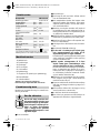
Bosch GBM 16-2 E Operating Instructions Manual
- Categoria
- Exercícios de força
- Tipo
- Operating Instructions Manual
em outras línguas
- français: Bosch GBM 16-2 E
- italiano: Bosch GBM 16-2 E
- Nederlands: Bosch GBM 16-2 E
- dansk: Bosch GBM 16-2 E
Artigos relacionados
-
Bosch GBM 10-2 RE Manual do proprietário
-
-
-
Bosch GBM 23-2 E Professional Manual do proprietário
-
-
-
Bosch PSR 960 Manual do proprietário
-
Bosch PBH 3000 FRE Set Manual do proprietário
-
-
Bosch GMB 32 Professional Instruções de operação