Bosch 30-180 B Manual do usuário
- Categoria
- Rebarbadoras
- Tipo
- Manual do usuário

Robert Bosch Power Tools GmbH
70538 Stuttgart
GERMANY
www.bosch-pt.com
1 609 92A 6ER (2022.05) O / 99
en Original instructions
fr Notice originale
pt Manual original
zh 正本使用明
zh 原始使用說明書
th
id Petunjuk-Petunjuk untuk
Penggunaan Orisinal
vi Bn gc hng dn s dng
ar
fa
1 609 92A 6ER
GWS Professional
30-180 B | 30-230 B | 30-180 PB | 30-230 PB

2 |
English ...................................................Page 6
Français..................................................Page 14
Português .............................................. Página 24
....................................................... 33
.................................................. 41
...................................................... 48
Bahasa Indonesia..................................... Halaman 58
Ting Vit............................................... Trang 68
.................................................. 78
.................................................. 88
1 609 92A 6ER | (10.05.2022) Bosch Power Tools

| 3
A
B
(4) (4)
C
(27)
(28)
(18)
Bosch Power Tools 1 609 92A 6ER | (10.05.2022)

4 |
(1)
(3)
(5)
(6)
(15)
(14)
(13)
(12)
(17)
(16)
(14)
(13)
(8)
(9)
(10)
(8)
(9)
(10)
(4)
(2)
(16)(7)
(11) (11)
1 609 92A 6ER | (10.05.2022) Bosch Power Tools

| 5
(5)
(26)
(25)
(24)
(13) (14)
(19)
(20) (23)
(21)
(22)
(18)
(19)
Bosch Power Tools 1 609 92A 6ER | (10.05.2022)

6 | English
English
Safety Instructions
General Power Tool Safety Warnings
WARNING Read all safety warnings and all in-
structions. Failure to follow the
warnings and instructions may result in electric shock, fire
and/or serious injury.
Save all warnings and instructions for future reference.
The term "power tool" in the warnings refers to your mains-
operated (corded) power tool or battery-operated (cord-
less) power tool.
Work area safety
uKeep work area clean and well lit. Cluttered or dark
areas invite accidents.
uDo not operate power tools in explosive atmospheres,
such as in the presence of flammable liquids, gases or
dust. Power tools create sparks which may ignite the dust
or fumes.
uKeep children and bystanders away while operating a
power tool. Distractions can cause you to lose control.
Electrical safety
uPower tool plugs must match the outlet. Never modify
the plug in any way. Do not use any adapter plugs with
earthed (grounded) power tools. Unmodified plugs and
matching outlets will reduce risk of electric shock.
uAvoid body contact with earthed or grounded sur-
faces, such as pipes, radiators, ranges and refrigerat-
ors. There is an increased risk of electric shock if your
body is earthed or grounded.
uDo not expose power tools to rain or wet conditions.
Water entering a power tool will increase the risk of elec-
tric shock.
uDo not abuse the cord. Never use the cord for carry-
ing, pulling or unplugging the power tool. Keep cord
away from heat, oil, sharp edges or moving parts.
Damaged or entangled cords increase the risk of electric
shock.
uWhen operating a power tool outdoors, use an exten-
sion cord suitable for outdoor use. Use of a cord suit-
able for outdoor use reduces the risk of electric shock..
uIf operating a power tool in a damp location is un-
avoidable, use a residual current device (RCD) protec-
ted supply. Use of an RCD reduces the risk of electric
shock.
Personal safety
uStay alert, watch what you are doing and use common
sense when operating a power tool. Do not use a
power tool while you are tired or under the influence
of drugs, alcohol or medication. A moment of inatten-
tion while operating power tools may result in serious per-
sonal injury.
uUse personal protective equipment. Always wear eye
protection. Protective equipment such as dust mask,
non-skid safety shoes, hard hat, or hearing protection
used for appropriate conditions will reduce personal in-
juries.
uPrevent unintentional starting. Ensure the switch is in
the off-position before connecting to power source
and/or battery pack, picking up or carrying the tool.
Carrying power tools with your finger on the switch or en-
ergising power tools that have the switch on invites acci-
dents.
uRemove any adjusting key or wrench before turning
the power tool on. A wrench or a key left attached to a
rotating part of the power tool may result in personal in-
jury.
uDo not overreach. Keep proper footing and balance at
all times. This enables better control of the power tool in
unexpected situations.
uDress properly. Do not wear loose clothing or jew-
ellery. Keep your hair, clothing and gloves away from
moving parts. Loose clothes, jewellery or long hair can
be caught in moving parts.
uIf devices are provided for the connection of dust ex-
traction and collection facilities, ensure these are con-
nected and properly used. Use of dust collection can re-
duce dust-related hazards.
Power tool use and care
uDo not force the power tool. Use the correct power
tool for your application. The correct power tool will do
the job better and safer at the rate for which it was de-
signed.
uDo not use the power tool if the switch does not turn it
on and off. Any power tool that cannot be controlled
with the switch is dangerous and must be repaired.
uDisconnect the plug from the power source and/or the
battery pack from the power tool before making any
adjustments, changing accessories, or storing power
tools. Such preventive safety measures reduce the risk
of starting the power tool accidentally.
uStore idle power tools out of the reach of children and
do not allow persons unfamiliar with the power tool or
these instructions to operate the power tool. Power
tools are dangerous in the hands of untrained users.
uMaintain power tools. Check for misalignment or bind-
ing of moving parts, breakage of parts and any other
condition that may affect the power tool’s operation.
If damaged, have the power tool repaired before use.
Many accidents are caused by poorly maintained power
tools.
uKeep cutting tools sharp and clean. Properly main-
tained cutting tools with sharp cutting edges are less
likely to bind and are easier to control.
uUse the power tool, accessories and tool bits etc. in
accordance with these instructions, taking into ac-
count the working conditions and the work to be per-
1 609 92A 6ER | (10.05.2022) Bosch Power Tools

English | 7
formed. Use of the power tool for operations different
from those intended could result in a hazardous situation.
Service
uHave your power tool serviced by a qualified repair
person using only identical replacement parts. This
will ensure that the safety of the power tool is maintained.
Safety Warnings for Angle Grinder
Safety Warnings common for Grinding, Sanding, Wire
Brushing or Abrasive Cutting Off operations
uThis power tool is intended to function as a grinder,
sander, wire brush or cut-off tool. Read all safety
warnings, instructions, illustrations and specifica-
tions provided with this power tool. Failure to follow all
instructions listed below may result in electric shock, fire
and/or serious injury.
uOperations such as polishing are not recommended to
be performed with this power tool. Operations for
which the power tool was not designed may create a haz-
ard and cause personal injury.
uDo not use accessories which are not specifically de-
signed and recommended by the tool manufacturer.
Just because the accessory can be attached to your
power tool, it does not assure safe operation.
uThe rated speed of the accessory must be at least
equal to the maximum speed marked on the power
tool. Accessories running faster than their rated speed
can break and fly apart.
uThe outside diameter and the thickness of your ac-
cessory must be within the capacity rating of your
power tool. Incorrectly sized accessories cannot be ad-
equately guarded or controlled.
uThreaded mounting of accessories must match the
grinder spindle thread. For accessories mounted by
flanges, the arbour hole of the accessory must fit the
locating diameter of the flange. Accessories that do not
match the mounting hardware of the power tool will run
out of balance, vibrate excessively and may cause loss of
control.
uDo not use a damaged accessory. Before each use in-
spect the accessory such as abrasive wheels for chips
and cracks, backing pad for cracks, tear or excess
wear, wire brush for loose or cracked wires. If power
tool or accessory is dropped, inspect for damage or in-
stall an undamaged accessory. After inspecting and
installing an accessory, position yourself and bystand-
ers away from the plane of the rotating accessory and
run the power tool at maximum no load speed for one
minute. Damaged accessories will normally break apart
during this test time.
uWear personal protective equipment. Depending on
application, use face shield, safety goggles or safety
glasses. As appropriate, wear dust mask, hearing pro-
tectors, gloves and workshop apron capable of stop-
ping small abrasive or workpiece fragments. The eye
protection must be capable of stopping flying debris gen-
erated by various operations . The dust mask or respir-
ator must be capable of filtrating particles generated by
your operation. Prolonged exposure to high intensity
noise may cause hearing loss.
uKeep bystanders a safe distance away from work area.
Anyone entering the work area must wear personal
protective equipment. Fragments of workpiece or of a
broken accessory may fly away and cause injury beyond
immediate area of operation.
uHold the power tool by insulated gripping surfaces
only, when performing an operation where the cutting
accessory may contact hidden wiring or its own cord.
Cutting accessory contacting a "live" wire may make ex-
posed metal parts of the power tool "live" and could give
the operator an electric shock.
uPosition the cord clear of the spinning accessory. If
you lose control, the cord may be cut or snagged and your
hand or arm may be pulled into the spinning accessory.
uNever lay the power tool down until the accessory has
come to a complete stop. The spinning accessory may
grab the surface and pull the power tool out of your con-
trol.
uDo not run the power tool while carrying it at your
side. Accidental contact with the spinning accessory
could snag your clothing, pulling the accessory into your
body.
uRegularly clean the power tool’s air vents. The motor’s
fan will draw the dust inside the housing and excessive
accumulation of powdered metal may cause electrical
hazards.
uDo not operate the power tool near flammable materi-
als. Sparks could ignite these materials.
uDo not use accessories that require liquid coolants.
Using water or other liquid coolants may result in electro-
cution or shock.
Kickback and Related Warnings
Kickback is a sudden reaction to a pinched or snagged rotat-
ing wheel, backing pad, brush or any other accessory. Pinch-
ing or snagging causes rapid stalling of the rotating access-
ory which in turn causes the uncontrolled power tool to be
forced in the direction opposite of the accessory’s rotation
at the point of the binding.
For example, if an abrasive wheel is snagged or pinched by
the workpiece, the edge of the wheel that is entering into the
pinch point can dig into the surface of the material causing
the wheel to climb out or kick out. The wheel may either
jump toward or away from the operator, depending on direc-
tion of the wheel’s movement at the point of pinching. Abras-
ive wheels may also break under these conditions.
Kickback is the result of power tool misuse and/or incorrect
operating procedures or conditions and can be avoided by
taking proper precautions as given below.
uMaintain a firm grip on the power tool and position
your body and arm to allow you to resist kickback
forces. Always use auxiliary handle, if provided, for
maximum control over kickback or torque reaction
Bosch Power Tools 1 609 92A 6ER | (10.05.2022)

8 | English
during start-up. The operator can control torque reac-
tions or kickback forces, if proper precautions are taken.
uNever place your hand near the rotating accessory.
Accessory may kickback over your hand.
uDo not position your body in the area where power
tool will move if kickback occurs. Kickback will propel
the tool in direction opposite to the wheel’s movement at
the point of snagging.
uUse special care when working corners, sharp edges
etc. Avoid bouncing and snagging the accessory.
Corners, sharp edges or bouncing have a tendency to
snag the rotating accessory and cause loss of control or
kickback.
uDo not attach a saw chain woodcarving blade or
toothed saw blade. Such blades create frequent kick-
back and loss of control.
Safety Warnings specific for Grinding and Abrasive
Cutting-Off operations
uUse only wheel types that are recommended for your
power tool and the specific guard designed for the se-
lected wheel. Wheels for which the power tool was not
designed cannot be adequately guarded and are unsafe.
uThe grinding surface of centre depressed wheels must
be mounted below the plane of the guard lip. An im-
properly mounted wheel that projects through the plane
of the guard lip cannot be adequately protected.
uThe guard must be securely attached to the power tool
and positioned for maximum safety, so the least
amount of wheel is exposed towards the operator.
The guard helps to protect operator from broken wheel
fragments, accidental contact with wheel and sparks that
could ignite clothing.
uWheels must be used only for recommended applica-
tions. For example: do not grind with the side of cut-
off wheel. Abrasive cut-off wheels are intended for peri-
pheral grinding, side forces applied to these wheels may
cause them to shatter.
uAlways use undamaged wheel flanges that are of cor-
rect size and shape for your selected wheel. Proper
wheel flanges support the wheel thus reducing the pos-
sibility of wheel breakage. Flanges for cut-off wheels may
be different from grinding wheel flanges.
uDo not use worn down wheels from larger power
tools. Wheel intended for larger power tool is not suit-
able for the higher speed of a smaller tool and may burst.
Additional Safety Warnings specific for Abrasive Cutting
Off operations
uDo not “jam” the cut-off wheel or apply excessive
pressure. Do not attempt to make an excessive depth
of cut. Overstressing the wheel increases the loading
and susceptibility to twisting or binding of the wheel in
the cut and the possibility of kickback or wheel breakage.
uDo not position your body in line with and behind the
rotating wheel. When the wheel, at the point of opera-
tion, is moving away from your body, the possible kick-
back may propel the spinning wheel and the power tool
directly at you.
uWhen wheel is binding or when interrupting a cut for
any reason, switch off the power tool and hold the
power tool motionless until the wheel comes to a com-
plete stop. Never attempt to remove the cut-off wheel
from the cut while the wheel is in motion otherwise
kickback may occur. Investigate and take corrective ac-
tion to eliminate the cause of wheel binding.
uDo not restart the cutting operation in the workpiece.
Let the wheel reach full speed and carefully re-enter
the cut. The wheel may bind, walk up or kickback if the
power tool is restarted in the workpiece.
uSupport panels or any oversized workpiece to minim-
ize the risk of wheel pinching and kickback. Large
workpieces tend to sag under their own weight. Supports
must be placed under the workpiece near the line of cut
and near the edge of the workpiece on both sides of the
wheel.
uUse extra caution when making a “pocket cut” into ex-
isting walls or other blind areas. The protruding wheel
may cut gas or water pipes, electrical wiring or objects
that can cause kickback.
Safety Warnings specific for Sanding operations
uDo not use excessively oversized sanding disc paper.
Follow manufacturers recommendations, when select-
ing sanding paper. Larger sanding paper extending bey-
ond the sanding pad presents a laceration hazard and
may cause snagging, tearing of the disc, or kickback.
Safety Warnings specific for Wire Brushing operations
uBe aware that wire bristles are thrown by the brush
even during ordinary operation. Do not overstress the
wires by applying excessive load to the brush The wire
bristles can easily penetrate light clothing and/or skin.
uIf the use of a guard is recommended for wire brush-
ing, do not allow any interference of the wire wheel or
brush with the guard. Wire wheel or brush may expand
in diameter due to work load and centrifugal forces.
Additional safety information
Wear safety goggles.
uUse suitable detectors to determine if utility lines are
hidden in the work area or call the local utility com-
pany for assistance. Contact with electric lines can lead
to fire and electric shock. Damaging a gas line can lead to
explosion. Penetrating a water line causes property dam-
age or may cause an electric shock.
uDo not touch grinding and cutting discs until they have
cooled down. The discs can become very hot while work-
ing.
uRelease the On/Off switch and set it to the off position
when the power supply is interrupted, e. g., in case of
1 609 92A 6ER | (10.05.2022) Bosch Power Tools

English | 9
a power failure or when the mains plug is pulled. This
prevents uncontrolled restarting.
uSecure the workpiece. A workpiece clamped with
clamping devices or in a vice is held more secure than by
hand.
Products sold in GB only:
Your product is fitted with an BS 1363/A approved electric
plug with internal fuse (ASTA approved to BS 1362).
If the plug is not suitable for your socket outlets, it should be
cut off and an appropriate plug fitted in its place by an au-
thorised customer service agent. The replacement plug
should have the same fuse rating as the original plug.
The severed plug must be disposed of to avoid a possible
shock hazard and should never be inserted into a mains
socket elsewhere.
Product Description and
Specifications
Read all the safety and general instructions.
Failure to observe the safety and general in-
structions may result in electric shock, fire
and/or serious injury.
Please observe the illustrations at the beginning of this oper-
ating manual.
Intended use
The power tool is intended for cutting, roughing and brush-
ing metal and stone materials without the use of water.
A separate protective guard for cutting must be used when
cutting with bonded abrasives.
Sufficient dust extraction must be provided when cutting
stone.
With approved abrasive tools, the power tool can be used for
sanding with sanding discs.
Product Features
The numbering of the product features refers to the diagram
of the power tool on the graphics page.
(1) Spindle lock button
(2) Status indicator (LED)
(3) On/off switch
(4) Dust filter
(5) Auxiliary handle (insulated gripping surface)
(6) Protective guard for grinding with clamping lever
(7) Protective guard for grinding with locking screw
(8) Coding cam
(9) Clamping lever for protective guard
(10) Adjusting screw for protective guard
(11) Locking screw for protective guard
(12) Grinding disca)
(13) Clamping nut
(14) Quick-clamping nut a)
(15) Carbide grinding heada)
(16) Protective guard for cuttinga)
(17) Cutting disca)
(18) Grinding spindle
(19) Hand guarda)
(20) Rubber sanding pada)
(21) Abrasive disca)
(22) Round nuta)
(23) Cup brusha)
(24) Diamond cutting disca)
(25) Extraction guard for cutting with cutting guidesa)
(26) Handle (insulated gripping surface)
(27) Clamping flange
(28) O-ring
a) Accessories shown or described are not included with the
product as standard. You can find the complete selection of
accessories in our accessories range.
Technical Data
Angle Grinder GWS 30-180 B GWS 30-230 B GWS 30-180 PB GWS 30-230 PB GWS 30-230 B
Article number 3 601 HG0 0.. 3 601 HG1 0.. 3 601 HG0 1.. 3 601 HG1 1.. 3 601 HG1 0..
Rated power input W 2800 2800 2800 2800 2200
Rated speed min–1 8500 6500 8500 6500 6500
Max. grinding disc dia-
meter
mm 180 230 180 230 230
Grinding spindle thread M 14 M 14 M 14 M 14 M 14
Max. thread length of
grinding spindle
mm 25 25 25 25 25
Kickback stop ● ● ● ● ●
Restart protection ● ● ● ● ●
Soft start ● ● ● ● ●
Bosch Power Tools 1 609 92A 6ER | (10.05.2022)

10 | English
Angle Grinder GWS 30-180 B GWS 30-230 B GWS 30-180 PB GWS 30-230 PB GWS 30-230 B
Run-out brake ● ● ● ● ●
Status indicator (LED) ● ● ● ● ●
PROtection switch – – ● ● –
Weight according to EPTA-
Procedure 01:2014
kg 5.7 5.9 5.7 5.9 5.9
Protection class / II / II / II / II / II
The specifications apply to a rated voltage [U] of 230 V. These specifications may vary at different voltages and in country-specific models.
The appliance meets IEC 61000-3-11 requirements and is subject to conditional connection. The appliance can lead to occa-
sional voltage fluctuations under unfavorable power conditions. The impedance of this appliance is set as Zactual =0.11Ω. The
user must make sure, that the connection point, with the impedance Zmax, on which the appliance shall be plugged in meets the
impedance requirement: Zactual≥Zmax. If Zmax is unknown, determine Zmax in consultation with the network supplier or supply au-
thority.
Fitting
Fitting Protective Equipment
uPull the plug out of the socket before carrying out any
work on the power tool.
Note: If the grinding disc breaks during operation or the
holding fixtures on the protective guard/power tool become
damaged, the power tool must be sent to the after-sales ser-
vice immediately; see the "After-Sales Service and Applica-
tion Service" section for addresses.
Protective guard for grinding with clamping lever
Open the clamping lever(9). Place the protective guard(6)
with the coding cam(8) engaging into the coding groove on
the spindle collar until the shoulder of the protective guard is
seated against the flange of the power tool, and turn the pro-
tective guard(6) to the required position. Close the clamp-
ing lever(9).
uAdjust the protective guard(6) such that sparking in
the direction of the operator is prevented.
The tensioning force of the clamp from the protective
guard(6) can be changed by loosening or tightening the ad-
justment screw(10). Ensure that the protective guard(6) is
fitted securely and check it regularly.
Note: The coding cams on the protective guard(6) ensure
that only a protective guard that is suitable for the power
tool can be fitted.
Protective guard for grinding with locking screw
Place the protective guard (7) on the spindle collar. Adjust
the position of the protective guard (7) to the requirements
of the operation and lock the protective guard (7) with the
locking screw (11).
uAdjust the protective guard (7) such that sparking in
the direction of the operator is prevented.
Protective guard for cutting
uAlways use the protective guard for cutting (16) when
cutting with bonded abrasives.
uProvide sufficient dust extraction when cutting stone.
The protective guard for cutting(16) is fitted in the same
way as the protective guard for grinding with locking
screw(7) or the protective guard for grinding with clamping
lever(6).
Extraction guard for cutting with a guide block
The extraction guard for cutting with a guide block (25) is fit-
ted in the same way as the protective guard for grinding (7).
Side handle
uDo not operate your power tool without the side
handle (5).
Screw the side handle (5) on the left or right of the machine
head depending on how your are working.
Vibration Damping
The integrated vibration
damping function reduces
the generated vibration.
uDo not continue to use the power tool if the damping
element is damaged.
Hand guard
uAlways fit the hand guard (19) when working with the
rubber sanding plate (20) or with the cup brush/disc
brush/flap disc.
Attach the hand guard (19) to the side handle (5).
Fitting the Abrasive Tools
uPull the plug out of the socket before carrying out any
work on the power tool.
uDo not touch grinding and cutting discs until they have
cooled down. The discs can become very hot while work-
ing.
Note: Ensure that the clamping flange supplied(27) is
mounted correctly in accordance with figureC.
Make sure that the fitted O-ring(28) is not damaged and is
mounted correctly in accordance with figureC. Replace any
damaged O-rings(28).
Note: It is recommended to use the quick-clamping
nut(14). When using the clamping nut(13), expect more
force to be required to loosen it.
Clean the grinding spindle(18) and all parts to be mounted.
1 609 92A 6ER | (10.05.2022) Bosch Power Tools

English | 11
Lock the grinding spindle with the spindle lock button (1)
before clamping and releasing the abrasive tools.
uDo not press the spindle lock button while the grind-
ing spindle is moving. The power tool may become dam-
aged if you do this.
Quick-clamping nut
To change the abrasive tool easily without having to use any
additional tools, you can use the quick-clamping nut (14) in-
stead of the clamping nut (13).
uThe quick-clamping nut (14) may be used only for
grinding or cutting discs.
Only use quick-clamping nuts (14) that are in good work-
ing order and not damaged.
When screwing on, make sure that the printed side of the
quick-clamping nut (14) is not facing the grinding disc;
the arrow must be pointing towards the index mark (29).
(29)
Press the spindle lock but-
ton (1) to lock the grinding
spindle. To tighten the
quick-clamping nut, turn
the grinding disc firmly
clockwise.
If the quick-clamping nut
has been attached correctly
and is not damaged, you
can loosen it by hand by
turning the knurled ring an-
ticlockwise. If the quick-
clamping nut is stuck, do
not attempt to loosen it
with pliers – always use
the two-pin spanner. Posi-
tion the two‑pin spanner as
shown in the figure.
Grinding/Cutting Disc
Pay attention to the dimensions of the grinding tools. The
mounting hole diameter must fit the mounting flange without
play. Do not use reducers or adapters.
When using diamond cutting discs, pay attention that the
direction-of-rotation arrow on the diamond cutting disc and
the direction of rotation of the machine (see direction-of-ro-
tation arrow on the machine head) agree.
See graphics page for the mounting sequence.
To fasten the grinding/cutting disc, screw on the clamping
nut (13) and tighten with the two-hole spanner.
uAfter fitting the abrasive tool, check that the abrasive
tool is fitted correctly and can turn freely before
switching on the power tool. Make sure that the abras-
ive tool does not brush against the protective guard or
other parts.
Flap disc
uAlways fit the hand guard (19) when working with the
flap disc.
Rubber sanding pad
uAlways fit the hand guard (19) when working with the
rubber sanding pad (20).
See the graphics page for fitting instructions.
Screw on the round nut (22) and tighten with the two-pin
spanner.
Cup brush/disc brush
uAlways fit the hand guard (19) when working with the
cup brush or disc brush.
See the graphics page for fitting instructions.
The cup brush/disc brush must be screwed onto the grinding
spindle until it rests firmly against the grinding spindle flange
at the end of the grinding spindle thread. Tighten the cup
brush/disc brush with an open-ended spanner.
Approved abrasive tools
You can use all the abrasive tools mentioned in these operat-
ing instructions.
The permissible speed [min-1] or the circumferential speed
[m/s] of the abrasive tools used must at least match the val-
ues given in the table.
It is therefore important to observe the permissible rota-
tional/circumferential speed on the label of the abrasive
tool.
Max. [mm] [mm]
D b d [min-1] [m/s]
180
230
8
8
22.2
22.2
8500
6500
80
80
180
230
–
–
–
–
8500
6500
80
80
100 30 M 14 /
5/8"
8500 45
Dust/Chip Extraction
The dust from materials such as lead paint, some types of
wood, minerals and metal can be harmful to human health.
Touching or breathing in this dust can trigger allergic reac-
tions and/or cause respiratory illnesses in the user or in
people in the near vicinity.
Certain dusts, such as oak or beech dust, are classified as
carcinogenic, especially in conjunction with wood treatment
additives (chromate, wood preservative). Materials contain-
ing asbestos may only be machined by specialists.
– Use a dust extraction system that is suitable for the ma-
terial wherever possible.
Bosch Power Tools 1 609 92A 6ER | (10.05.2022)

12 | English
– Provide good ventilation at the workplace.
– It is advisable to wear a P2 filter class breathing mask.
The regulations on the material being machined that apply in
the country of use must be observed.
uAvoid dust accumulation at the workplace. Dust can
easily ignite.
Removing/fitting the dust filter
Remove any used dust filters(4) along with the screws in ac-
cordance with figureA. Fit a new dust filter in accordance
with figureB.
When fitting the dust filter(4), only use the original screws
to avoid damage to the electronics.
Operation
Start-Up
uPay attention to the mains voltage. The voltage of the
power source must match the voltage specified on the
rating plate of the power tool. Power tools marked
with 230V can also be operated with 220V.
uProducts that are only sold in AUS and NZ: Use a resid-
ual current device (RCD) with a nominal residual current
of 30 mA or less.
uHold the tool by the insulated gripping surfaces and
auxiliary handle only. The application tool could come
into contact with hidden wiring or its own cord. Con-
tact with live wires may make metal parts of the tool live,
posing a risk of electric shock.
Switching on/off
To start the power tool, push the on/off switch(3) forwards
and then press it down.
To lock-on the pressed on/off switch(3), push the on/off
switch (3) further forwards.
To switch off the power tool, release the on/off switch(3);
or, if the switch is locked, briefly press the on/off switch(3)
and then release it.
Switch without locking mechanism (country-specific):
To start the power tool, push the on/off switch(3) forwards
and then press it down.
To switch off the power tool, release the on/off switch(3).
uAlways check abrasive tools before using them. The
abrasive tool must be fitted properly and be able to
move freely. Carry out a test run for at least one
minute with no load. Do not use abrasive tools that are
damaged, run untrue or vibrate during use. Damaged
abrasive tools can burst apart and cause injuries.
Kickback control
If there is a sudden kickback in the power tool,
e.g. jamming in a separating cut, the power
supply to the motor will be interrupted elec-
tronically.
To restart the tool, set the On/Off switch (3) to the "off" po-
sition and then switch the power tool on again.
Restart protection
The restart protection feature prevents the power tool from
uncontrolled starting after the power supply to it has been
interrupted.
To restart the tool, set the on/off switch(3) to the "off" posi-
tion and then switch the power tool on again.
Note: If the power tool starts up immediately after an inter-
ruption in the power supply, the restart protection feature
has failed.The power tool must be sent to the after-sales ser-
vice immediately; see the "After-Sales Service and Applica-
tion Service" section for addresses.
Soft start
The electronic soft start limits the torque when the power
tool is switched on and enables a smooth start-up.
Note: If the power tool runs at full speed immediately after
being switched on, this means that the soft start and restart
protection mechanisms have failed. The power tool must be
sent to the after-sales service immediately; see the "After-
Sales Service and Application Service" section for ad-
dresses.
Electronic Brake System
The power tool is fitted with an electronic
brake system. When the power supply is
switched off, the abrasive tool is brought to a
complete stop within a few seconds. This
means that the run-out time is shorter than for
angle grinders without an electronic brake system and en-
ables the power tool to be set down sooner.
Note: If the braking effect deteriorates noticeably, the elec-
tronic brake system has failed. The power tool must be sent
to the after-sales service immediately; see the "After-Sales
Service and Application Service" section for addresses.
Status indicator (LED)
The following tables describes the LED status indicators(2) on the power tool.
Status indicator (LED)(2) Meaning/cause Solution
Green Status OK –
Flashing red Power tool has overheated and will switch off. Leave the power tool to cool down. If the
status indicator (LED) lights up green, the
power tool can be switched on again.
Illuminated red Kickback shutdown,restart protection or over-
load protection has been triggered, the power
tool will switch off.
Turn the power tool off and on again.
1 609 92A 6ER | (10.05.2022) Bosch Power Tools

English | 13
Working Advice
uPull the plug out of the socket before carrying out any
work on the power tool.
uExercise caution when cutting slots in structural walls;
see the "Information on structural design" section.
uClamp the workpiece if it is not secure under its own
weight.
uDo not load the power tool so heavily that it comes to a
stop.
uIf the power tool has been subjected to a heavy load,
continue to run it at no-load for several minutes to
cool down the accessory.
uDo not use the power tool with a cut-off stand.
uDo not touch grinding and cutting discs until they have
cooled down. The discs can become very hot while work-
ing.
Note: Remove the plug from the socket when not using the
tool. When the power tool is plugged in, mains voltage is
present and the tool consumes a small amount of electricity,
even if switched off.
Rough grinding
uNever use cutting discs for rough grinding.
The best rough grinding results are achieved with a set angle
of 30° to 40°. Move the power tool back and forth with mod-
erate pressure. This will ensure that the workpiece does not
become too hot or discolour and that grooves are not
formed.
Flap Disc
With the flap disc (accessory), curved surfaces and profiles
can be worked. Flap discs have a considerably higher ser-
vice life, lower noise levels and lower sanding temperatures
than conventional sanding sheets.
Cutting Metal
uAlways use the protective guard for cutting (16) when
cutting with bonded abrasives.
When carrying out abrasive cutting, use a moderate feed
that is suited to the material being machined. Do not exert
pressure on the cutting disc and do not tilt or swing the
power tool.
Do not attempt to reduce the speed of a cutting disc coming
to a stop by applying pressure from the side.
The power tool must always
work in an up-grinding mo-
tion. Otherwise, there is a
risk that it will be pushed
uncontrolled out of the cut.
For best results when cut-
ting profiles and rectangular
tubing, start at the smallest
cross section.
Cutting stone
uProvide sufficient dust extraction when cutting stone.
uWear a dust mask.
uThe power tool may be used only for dry cutting/grind-
ing.
For best results when cutting stone, use a diamond cutting
disc.
When using the extraction guard for cutting with a guide
block (25), the vacuum cleaner must be approved for vacu-
uming stone dust. Suitable vacuum cleaners are available
from Bosch.
Switch on the power tool
and position it with the
front part of the guide block
on the workpiece. Move the
power tool with a moderate
feed motion that is suited to
the material being ma-
chined.
When cutting especially
hard materials such as con-
crete with a high pebble content, the diamond cutting disc
can overheat and become damaged as a result. This is
clearly indicated by circular sparking, rotating with the dia-
mond cutting disc.
If this happens, stop cutting and allow the diamond cutting
disc to cool down by running the power tool for a short time
at maximum speed with no load.
Working noticeably slower and with circular sparking indic-
ate that the diamond cutting disc that has become dull. You
can resharpen the disc by briefly cutting into abrasive mater-
ial (e.g. lime-sand brick).
Information on structural design
Slots in load-bearing walls are subject to DIN 1053 part 1 or
country-specific regulations. These regulations must be ob-
served under all circumstances. Seek advice from the re-
sponsible structural engineer, architect or construction su-
pervisor before starting work.
Maintenance and Service
Maintenance and Cleaning
uPull the plug out of the socket before carrying out any
work on the power tool.
uTo ensure safe and efficient operation, always keep
the power tool and the ventilation slots clean.
uIn extreme conditions, always use a dust extractor if
possible. Blow out ventilation slots frequently and in-
stall a residual current device (RCD) upstream. When
machining metals, conductive dust can settle inside the
power tool, which can affect its protective insulation.
Store and handle the accessories carefully.
In order to avoid safety hazards, if the power supply cord
needs to be replaced, this must be done by Bosch or by an
after-sales service centre that is authorised to repair Bosch
power tools.
Bosch Power Tools 1 609 92A 6ER | (10.05.2022)

14 | Français
After-Sales Service and Application Service
Our after-sales service responds to your questions concern-
ing maintenance and repair of your product as well as spare
parts. You can find explosion drawings and information on
spare parts at: www.bosch-pt.com
The Bosch product use advice team will be happy to help you
with any questions about our products and their accessor-
ies.
In all correspondence and spare parts orders, please always
include the 10‑digit article number given on the nameplate
of the product.
Malaysia
Robert Bosch Sdn. Bhd.(220975-V) PT/SMY
No. 8A, Jalan 13/6
46200 Petaling Jaya
Selangor
Tel.: (03) 79663194
Toll-Free: 1800 880188
Fax: (03) 79583838
E-Mail: [email protected]
www.bosch-pt.com.my
You can find further service addresses at:
www.bosch-pt.com/serviceaddresses
Disposal
The power tool, accessories and packaging should be re-
cycled in an environmentally friendly manner.
Do not dispose of power tools along with
household waste.
Français
Consignes de sécurité
Avertissements de sécurité généraux pour l’outil
AVERTISSE-
MENT
Lire tous les avertissements de sé-
curité et toutes les instructions.
Ne pas suivre les avertissements et
instructions peut donner lieu à un choc électrique, un incen-
die et/ou une blessure sérieuse.
Conserver tous les avertissements et toutes les instruc-
tions pour pouvoir s'y reporter ultérieurement.
Le terme «outil» dans les avertissements fait référence à
votre outil électrique alimenté par le secteur (avec cordon
d’alimentation) ou votre outil fonctionnant sur batterie (sans
cordon d’alimentation).
Sécurité de la zone de travail
uConserver la zone de travail propre et bien éclairée.
Les zones en désordre ou sombres sont propices aux ac-
cidents.
uNe pas faire fonctionner les outils électriques en at-
mosphère explosive, par exemple en présence de li-
quides inflammables, de gaz ou de poussières. Les ou-
tils électriques produisent des étincelles qui peuvent en-
flammer les poussières ou les fumées.
uMaintenir les enfants et les personnes présentes à
l’écart pendant l’utilisation de l’outil. Les distractions
peuvent vous faire perdre le contrôle de l’outil.
Sécurité électrique
uIl faut que les fiches de l’outil électrique soient adap-
tées au socle. Ne jamais modifier la fiche de quelque
façon que ce soit. Ne pas utiliser d’adaptateurs avec
des outils à branchement de terre. Des fiches non mo-
difiées et des socles adaptés réduiront le risque de choc
électrique.
uEviter tout contact du corps avec des surfaces reliées
à la terre telles que les tuyaux, les radiateurs, les cui-
sinières et les réfrigérateurs. Il existe un risque accru
de choc électrique si votre corps est relié à la terre.
uNe pas exposer les outils à la pluie ou à des conditions
humides. La pénétration d‘eau à l’intérieur d’un outil aug-
mentera le risque de choc électrique.
uNe pas maltraiter le cordon. Ne jamais utiliser le cor-
don pour porter, tirer ou débrancher l’outil. Maintenir
le cordon à l’écart de la chaleur, du lubrifiant, des
arêtes ou des parties en mouvement. Des cordons en-
dommagés ou emmêlés augmentent le risque de choc
électrique.
uLorsqu’on utilise un outil à l’extérieur, utiliser un pro-
longateur adapté à l’utilisation extérieure. L’utilisation
d’un cordon adapté à l’utilisation extérieure réduit le
risque de choc électrique.
uSi l'usage d'un outil dans un emplacement humide est
inévitable, utiliser une alimentation protégée par un
dispositif à courant différentiel résiduel (RCD).
L'usage d'un RCD réduit le risque de choc électrique.
Sécurité des personnes
uRester vigilant, regarder ce que vous êtes en train de
faire et faire preuve de bon sens dans votre utilisation
de l’outil. Ne pas utiliser un outil lorsque vous êtes fa-
tigué ou sous l’emprise de drogues, d’alcool ou de mé-
dicaments. Un moment d’inattention en cours d’utilisa-
tion d’un outil peut entraîner des blessures graves des
personnes.
uUtiliser un équipement de sécurité. Toujours porter
une protection pour les yeux. Les équipements de sécu-
rité tels que les masques contre les poussières, les chaus-
sures de sécurité antidérapantes, les casques ou les pro-
tections acoustiques utilisés pour les conditions appro-
priées réduiront les blessures de personnes.
1 609 92A 6ER | (10.05.2022) Bosch Power Tools

Français | 15
uEviter tout démarrage intempestif. S’assurer que l’in-
terrupteur est en position arrêt avant de brancher
l’outil au secteur et/ou au bloc de batteries, de le ra-
masser ou de le porter. Porter les outils en ayant le
doigt sur l’interrupteur ou brancher des outils dont l’inter-
rupteur est en position marche est source d’accidents.
uRetirer toute clé de réglage avant de mettre l’outil en
marche. Une clé laissée fixée sur une partie tournante de
l’outil peut donner lieu à des blessures de personnes.
uNe pas se précipiter. Garder une position et un équi-
libre adaptés à tout moment. Cela permet un meilleur
contrôle de l’outil dans des situations inattendues.
uS’habiller de manière adaptée. Ne pas porter de vête-
ments amples ou de bijoux. Garder les cheveux, les vê-
tements et les gants à distance des parties en mouve-
ment. Des vêtements amples, des bijoux ou les cheveux
longs peuvent être pris dans des parties en mouvement.
uSi des dispositifs sont fournis pour le raccordement
d’équipements pour l’extraction et la récupération des
poussières, s’assurer qu’ils sont connectés et correc-
tement utilisés. Utiliser des collecteurs de poussière
peut réduire les risques dus aux poussières.
Utilisation et entretien de l’outil
uNe pas forcer l’outil. Utiliser l’outil adapté à votre ap-
plication. L’outil adapté réalisera mieux le travail et de
manière plus sûre au régime pour lequel il a été construit.
uNe pas utiliser l’outil si l’interrupteur ne permet pas de
passer de l’état de marche à arrêt et vice versa. Tout
outil qui ne peut pas être commandé par l’interrupteur est
dangereux et il faut le réparer.
uDébrancher la fiche de la source d’alimentation en
courant et/ou le bloc de batteries de l’outil avant tout
réglage, changement d’accessoires ou avant de ran-
ger l’outil. De telles mesures de sécurité préventives ré-
duisent le risque de démarrage accidentel de l’outil.
uConserver les outils à l’arrêt hors de la portée des en-
fants et ne pas permettre à des personnes ne connais-
sant pas l’outil ou les présentes instructions de le faire
fonctionner. Les outils sont dangereux entre les mains
d’utilisateurs novices.
uObserver la maintenance de l’outil. Vérifier qu’il n’y a
pas de mauvais alignement ou de blocage des parties
mobiles, des pièces cassées ou toute autre condition
pouvant affecter le fonctionnement de l’outil. En cas
de dommages, faire réparer l’outil avant de l’utiliser.
De nombreux accidents sont dus à des outils mal entrete-
nus.
uGarder affûtés et propres les outils permettant de
couper. Des outils destinés à couper correctement en-
tretenus avec des pièces coupantes tranchantes sont
moins susceptibles de bloquer et sont plus faciles à
contrôler.
uUtiliser l’outil, les accessoires et les lames etc.,
conformément à ces instructions, en tenant compte
des conditions de travail et du travail à réaliser. L’utili-
sation de l’outil pour des opérations différentes de celles
prévues pourrait donner lieu à des situations dange-
reuses.
Maintenance et entretien
uFaire entretenir l’outil par un réparateur qualifié utili-
sant uniquement des pièces de rechange identiques.
Cela assurera que la sécurité de l’outil est maintenue.
Instructions de sécurité pour meuleuses
angulaires
Avertissements de sécurité communs pour les
opérations de meulage, de ponçage, de brossage
métallique ou de tronçonnage par meule abrasive
uCet outil électrique est destiné à fonctionner comme
meuleuse, ponceuse, brosse métallique ou outil à
tronçonner. Lire toutes les mises en garde de sécurité,
les instructions, les illustrations et les spécifications
fournies avec cet outil électrique. Le fait de ne pas
suivre toutes les instructions données ci-dessous peut
provoquer un choc électrique, un incendie et/ou une bles-
sure grave.
uLes opérations de lustrage ne sont pas recommandées
avec cet outil électrique. Les opérations pour lesquelles
l’outil électrique n’a pas été conçu peuvent provoquer un
danger et causer un accident corporel.
uNe pas utiliser d’accessoires non conçus spécifique-
ment et recommandés par le fabricant d’outils. Le
simple fait que l’accessoire puisse être fixé à votre outil
électrique ne garantit pas un fonctionnement en toute sé-
curité.
uLa vitesse assignée de l’accessoire doit être au moins
égale à la vitesse maximale indiquée sur l’outil élec-
trique. Les accessoires fonctionnant plus vite que leur vi-
tesse assignée peuvent se rompre et voler en éclat.
uLe diamètre extérieur et l’épaisseur de votre acces-
soire doivent se situer dans le cadre des caractéris-
tiques de capacité de votre outil électrique. Les acces-
soires dimensionnés de façon incorrecte ne peuvent pas
être protégés ou commandés de manière appropriée.
uLe montage fileté d'accessoires doit être adapté au fi-
let de l'arbre de la meuleuse. Pour les accessoires
montés avec des flasques, l'alésage central de l'acces-
soire doit s’adapter correctement au diamètre du
flasque. Les accessoires qui ne correspondent pas aux
éléments de montage de l’outil électrique seront en dés-
équilibre, vibreront de manière excessive et pourront
provoquer une perte de contrôle.
uNe pas utiliser d’accessoire endommagé. Avant
chaque utilisation examiner les accessoires comme
les meules abrasives pour détecter la présence éven-
tuelle de copeaux et fissures, les patins d’appui pour
détecter des traces éventuelles de fissures, de déchi-
rure ou d’usure excessive, ainsi que les brosses métal-
liques pour détecter des fils desserrés ou fissurés. Si
l’outil électrique ou l’accessoire a subi une chute, exa-
miner les dommages éventuels ou installer un acces-
soire non endommagé. Après examen et installation
Bosch Power Tools 1 609 92A 6ER | (10.05.2022)

16 | Français
d’un accessoire, placez-vous ainsi que les personnes
présentes à distance du plan de l’accessoire rotatif et
faire marcher l’outil électrique à vitesse maximale à
vide pendant 1 min. Les accessoires endommagés se-
ront normalement détruits pendant cette période d’essai.
uPorter un équipement de protection individuelle. En
fonction de l’application, utiliser un écran facial, des
lunettes de sécurité ou des verres de sécurité. Le cas
échéant, utiliser un masque antipoussières, des pro-
tections auditives, des gants et un tablier capables
d’arrêter les petits fragments abrasifs ou des pièces à
usiner. La protection oculaire doit être capable d’arrêter
les débris volants produits par les diverses opérations. Le
masque antipoussières ou le respirateur doit être capable
de filtrer les particules produites par vos travaux. L’expo-
sition prolongée aux bruits de forte intensité peut provo-
quer une perte de l’audition.
uMaintenir les personnes présentes à une distance de
sécurité par rapport à la zone de travail. Toute per-
sonne entrant dans la zone de travail doit porter un
équipement de protection individuelle. Des fragments
de pièce à usiner ou d’un accessoire cassé peuvent être
projetés et provoquer des blessures en dehors de la zone
immédiate d’opération.
uTenir l’outil uniquement par les surfaces de préhen-
sion isolantes, pendant les opérations au cours des-
quelles l’accessoire coupant peut être en contact avec
des conducteurs cachés ou avec son propre câble. Le
contact de l’accessoire coupant avec un fil «sous tension»
peut mettre «sous tension» les parties métalliques expo-
sées de l’outil électrique et provoquer un choc électrique
sur l’opérateur.
uPlacer le câble éloigné de l’accessoire de rotation. Si
vous perdez le contrôle, le câble peut être coupé ou subir
un accroc et votre main ou votre bras peut être tiré dans
l’accessoire de rotation.
uNe jamais reposer l’outil électrique avant que l’acces-
soire n’ait atteint un arrêt complet. L’accessoire de ro-
tation peut agripper la surface et arracher l’outil élec-
trique hors de votre contrôle.
uNe pas faire fonctionner l’outil électrique en le portant
sur le côté. Un contact accidentel avec l’accessoire de ro-
tation pourrait accrocher vos vêtements et attirer l’acces-
soire sur vous.
uNettoyer régulièrement les orifices d’aération de l’ou-
til électrique. Le ventilateur du moteur attirera la pous-
sière à l’intérieur du boîtier et une accumulation excessive
de poudre de métal peut provoquer des dangers élec-
triques.
uNe pas faire fonctionner l’outil électrique à proximité
de matériaux inflammables. Des étincelles pourraient
enflammer ces matériaux.
uNe pas utiliser d’accessoires qui nécessitent des réfri-
gérants fluides. L’utilisation d’eau ou d’autres réfrigé-
rants fluides peut aboutir à une électrocution ou un choc
électrique.
Rebonds et mises en garde correspondantes
Le rebond est une réaction soudaine au pincement ou à l’ac-
crochage d’une meule rotative, d’un patin d’appui, d’une
brosse ou de tout autre accessoire. Le pincement ou l’accro-
chage provoque un blocage rapide de l’accessoire en rota-
tion qui, à son tour, contraint l’outil électrique hors de
contrôle dans le sens opposé de rotation de l’accessoire au
point du grippage.
Par exemple, si une meule abrasive est accrochée ou pincée
par la pièce à usiner, le bord de la meule qui entre dans le
point de pincement peut creuser la surface du matériau, pro-
voquant des sauts ou l’expulsion de la meule. La meule peut
sauter en direction de l’opérateur ou encore en s’en éloi-
gnant, selon le sens du mouvement de la meule au point de
pincement. Les meules abrasives peuvent également se
rompre dans ces conditions.
Le rebond résulte d’un mauvais usage de l’outil et/ou de pro-
cédures ou de conditions de fonctionnement incorrectes et
peut être évité en prenant les précautions appropriées spé-
cifiées ci-dessous.
uMaintenir fermement l’outil électrique et placer votre
corps et vos bras pour vous permettre de résister aux
forces de rebond. Toujours utiliser une poignée auxi-
liaire, le cas échéant, pour une maîtrise maximale du
rebond ou de la réaction de couple au cours du démar-
rage. L’opérateur peut maîtriser les couples de réaction
ou les forces de rebond, si les précautions qui s’imposent
sont prises.
uNe jamais placer votre main à proximité de l’acces-
soire en rotation. L’accessoire peut effectuer un rebond
sur votre main.
uNe pas vous placer dans la zone où l’outil électrique se
déplacera en cas de rebond. Le rebond pousse l’outil
dans le sens opposé au mouvement de la meule au point
d’accrochage.
uApporter un soin particulier lors de travaux dans les
coins, les arêtes vives etc. Eviter les rebondissements
et les accrochages de l’accessoire. Les coins, les arêtes
vives ou les rebondissements ont tendance à accrocher
l’accessoire en rotation et à provoquer une perte de
contrôle ou un rebond.
uNe pas fixer de chaîne coupante, de lame de sculpture
sur bois, de chaîne coupante ni de lame de scie den-
tée. De telles lames provoquent des rebonds fréquents et
des pertes de contrôle.
Mises en garde de sécurité spécifiques aux opérations de
meulage et de tronçonnage abrasif
uUtiliser uniquement des types de meules recomman-
dés pour votre outil électrique et le protecteur spéci-
fique conçu pour la meule choisie. Les meules pour les-
quelles l’outil électrique n’a pas été conçu ne peuvent pas
être protégées de façon satisfaisante et sont dange-
reuses.
uLa surface de meulage des meules à moyeu déporté
doit être montée sous le plan de la lèvre du protec-
teur. Une meule montée de manière incorrecte qui dé-
1 609 92A 6ER | (10.05.2022) Bosch Power Tools

Français | 17
passe du plan de la lèvre du protecteur ne peut pas être
protégée de manière appropriée.
uLe protecteur doit être solidement fixé à l’outil élec-
trique et placé en vue d’une sécurité maximale, de
sorte que l’opérateur soit exposé le moins possible à
la meule. Le protecteur permet de protéger l’opérateur
des fragments de meule cassée, d’un contact accidentel
avec la meule et d’étincelles susceptibles d’enflammer les
vêtements.
uLes meules doivent être utilisées uniquement pour les
applications recommandées. Par exemple: ne pas
meuler avec le côté de la meule à tronçonner. Les
meules à tronçonner abrasives sont destinées au meulage
périphérique, l’application de forces latérales à ces
meules peut les briser en éclats.
uToujours utiliser des flasques de meule non endomma-
gés qui sont de taille et de forme correctes pour la
meule que vous avez choisie. Des flasques de meule ap-
propriés supportent la meule réduisant ainsi la possibilité
de rupture de la meule. Les flasques pour les meules à
tronçonner peuvent être différents des autres flasques de
meule.
uNe pas utiliser de meules usées d’outils électriques
plus grands. La meule destinée à un outil électrique plus
grand n’est pas appropriée pour la vitesse plus élevée
d’un outil plus petit et elle peut éclater.
Mises en garde de sécurité additionnelles spécifiques
aux opérations de tronçonnage abrasif
uNe pas «coincer» la meule à tronçonner ou ne pas ap-
pliquer une pression excessive. Ne pas tenter d’exécu-
ter une profondeur de coupe excessive. Une contrainte
excessive de la meule augmente la charge et la probabilité
de torsion ou de blocage de la meule dans la coupe et la
possibilité de rebond ou de rupture de la meule.
uNe pas vous placer dans l’alignement de la meule en
rotation ni derrière celle-ci. Lorsque la meule, au point
de fonctionnement, s’éloigne de votre corps, le rebond
éventuel peut propulser la meule en rotation et l’outil
électrique directement sur vous.
uLorsque la meule se bloque ou lorsque la coupe est in-
terrompue pour une raison quelconque, mettre l’outil
électrique hors tension et tenir l’outil électrique im-
mobile jusqu’à ce que la meule soit à l’arrêt complet.
Ne jamais tenter d’enlever la meule à tronçonner de la
coupe tandis que la meule est en mouvement sinon le
rebond peut se produire. Rechercher et prendre des
mesures correctives afin d’empêcher que la meule ne se
grippe.
uNe pas démarrer de nouveau le travail directement sur
la pièce. Laissez le disque atteindre sa vitesse maxi-
male et entrer en contact avec la pièce prudemment.
Le disque peut s’accrocher, se soulever brusquement ou
avoir un mouvement arrière si l’appareil est redémarré en
charge.
uPrévoir un support de panneaux ou de toute pièce à
usiner surdimensionnée pour réduire le risque de pin-
cement et de rebond de la meule. Les grandes pièces à
usiner ont tendance à fléchir sous leur propre poids. Les
supports doivent être placés sous la pièce à usiner près
de la ligne de coupe et près du bord de la pièce des deux
côtés de la meule.
uSoyez particulièrement prudent lorsque vous faites
une «coupe en retrait» dans des parois existantes ou
dans d’autres zones sans visibilité. La meule saillante
peut couper des tuyaux de gaz ou d’eau, des câblages
électriques ou des objets, ce qui peut entraîner des re-
bonds.
Mises en garde de sécurité spécifiques aux opérations de
ponçage
uNe pas utiliser de papier abrasif trop surdimensionné
pour les disques de ponçage. Suivre les recommanda-
tions des fabricants, lors du choix du papier abrasif.
Un papier abrasif plus grand s’étendant au-delà du patin
de ponçage présente un danger de lacération et peut pro-
voquer un accrochage, une déchirure du disque ou un re-
bond.
Mises en garde de sécurité spécifiques aux opérations de
brossage métallique
uGarder à l’esprit que des brins métalliques sont reje-
tés par la brosse même au cours d’une opération ordi-
naire. Ne pas soumettre à une trop grande contrainte
les fils métalliques en appliquant une charge exces-
sive à la brosse. Les brins métalliques peuvent aisément
pénétrer dans des vêtements légers et/ou la peau.
uSi l’utilisation d’un protecteur est recommandée pour
le brossage métallique, ne permettre aucune gêne du
touret ou de la brosse métallique au protecteur. Le
touret ou la brosse métallique peut se dilater en diamètre
en raison de la charge de travail et des forces centrifuges.
Consignes de sécurité additionnelles
Portez toujours des lunettes de protection.
uUtilisez un détecteur approprié pour vérifier s’il n’y a
pas de conduites cachées ou contactez votre société
de distribution d’eau locale. Tout contact avec des
câbles électriques peut provoquer un incendie ou un choc
électrique. Tout endommagement d’une conduite de gaz
peut provoquer une explosion. La perforation d’une
conduite d’eau provoque des dégâts matériels et peut
provoquer un choc électrique.
uAttendez que les meules à ébarber et les disques à
tronçonner aient refroidi avant de les toucher. Les
meules deviennent brûlantes pendant le travail.
uDéverrouiller l’interrupteur Marche/Arrêt et le mettre
dans la position d’arrêt, si l’alimentation en courant
est interrompue, par ex. par une panne de courant ou
quand la fiche du secteur est débranchée. Ceci permet
d’éviter un redémarrage incontrôlé.
uBloquez la pièce à travailler. Une pièce à travailler ser-
rée par des dispositifs de serrage appropriés ou dans un
Bosch Power Tools 1 609 92A 6ER | (10.05.2022)

18 | Français
étau est fixée de manière plus sûre que quand elle est te-
nue avec une main.
Description des prestations et du
produit
Lisez attentivement toutes les instructions
et consignes de sécurité. Le non-respect des
instructions et consignes de sécurité peut pro-
voquer un choc électrique, un incendie et/ou
entraîner de graves blessures.
Référez-vous aux illustrations qui se trouvent à l’avant de la
notice d’utilisation.
Utilisation conforme
L’outil électroportatif est conçu pour le tronçonnage, le meu-
lage/l’ébarbage et le brossage à sec de la pierre et du métal.
Pour le tronçonnage avec des abrasifs agglomérés, utilisez
un capot de protection spécifiquement conçu pour le tron-
çonnage.
Pour le tronçonnage de pierres, veillez à assurer une aspira-
tion suffisante des poussières.
En combinaison avec les accessoires de ponçage adéquats,
l’outil électroportatif peut aussi être utilisé pour le ponçage
avec des disques abrasifs.
Éléments constitutifs
La numérotation des éléments de l’appareil se réfère à la re-
présentation de l’outil électroportatif sur la page graphique.
(1) Bouton de blocage de broche
(2) LED d’état
(3) Interrupteur Marche/Arrêt
(4) Filtre à poussière
(5) Poignée supplémentaire (surface de préhension iso-
lée)
(6) Capot de protection spécial meulage avec levier de
serrage
(7) Capot de protection spécial meulage avec vis de blo-
cage
(8) Ergot de détrompage
(9) Levier de serrage du capot de protection
(10) Vis d’ajustage du capot de protection
(11) Vis de blocage du capot de protection
(12) Meulea)
(13) Écrou de serrage
(14) Écrou de serrage rapide a)
(15) Meule assiette au carburea)
(16) Capot de protection spécial tronçonnagea)
(17) Disque à tronçonnera)
(18) Broche d’entraînement
(19) Protège-maina)
(20) Plateau support caoutchouca)
(21) Disque abrasifa)
(22) Écrou cylindriquea)
(23) Brosse boisseaua)
(24) Disque à tronçonner diamantéa)
(25) Capot d’aspiration spécial tronçonnage avec glissière
de guidagea)
(26) Poignée (surface de préhension isolée)
(27) Flasque de serrage
(28) Joint torique
a) Les accessoires décrits ou illustrés ne sont pas tous compris
dans la fourniture. Vous trouverez les accessoires complets
dans notre gamme d’accessoires.
Caractéristiques techniques
Meuleuse angulaire GWS 30-180 B GWS 30-230 B GWS 30-180 PB GWS 30-230 PB GWS 30-230 B
Référence 3 601 HG0 0.. 3 601 HG1 0.. 3 601 HG0 1.. 3 601 HG1 1.. 3 601 HG1 0..
Puissance absorbée nomi-
nale
W 2800 2800 2800 2800 2200
Régime nominal tr/min 8500 6500 8500 6500 6500
Diamètre de disque maxi mm 180 230 180 230 230
Filetage de la broche d’en-
traînement
M 14 M 14 M 14 M 14 M 14
Longueur de filetage maxi
de la broche d’entraîne-
ment
mm 25 25 25 25 25
Arrêt en cas de rebond
(KickBack Control)
● ● ● ● ●
Protection anti-redémar-
rage
● ● ● ● ●
Démarrage progressif ● ● ● ● ●
1 609 92A 6ER | (10.05.2022) Bosch Power Tools

Français | 19
Meuleuse angulaire GWS 30-180 B GWS 30-230 B GWS 30-180 PB GWS 30-230 PB GWS 30-230 B
Frein d’arrêt immédiat ● ● ● ● ●
LED d’état ● ● ● ● ●
Interrupteur PROtection – – ● ● –
Poids selon EPTA-Proce-
dure 01:2014
kg 5,7 5,9 5,7 5,9 5,9
Indice de protection / II / II / II / II / II
Les données indiquées sont valables pour une tension nominale [U] de 230 V. Elles peuvent varier lorsque la tension diffère de cette valeur et sur
certaines versions destinées à certains pays.
L’appareil est conforme aux exigences de la norme CEI 61000-3-11 et est soumis à un raccordement conditionnel. Dans des
conditions défavorables, l’appareil peut causer des fluctuations de tension passagères. Cet appareil a une impédance Zréel
=0,11Ω. L’utilisateur doit s’assurer que l’impédance Zmax au point de raccordement de l’appareil est telle que : Zréel≥Zmax. Si la
valeur de Zmax n’est pas connue, déterminez Zmax en concertation avec le fournisseur réseau ou l’autorité compétente.
Montage
Montage du dispositif de protection
uDébranchez le câble d’alimentation de la prise avant
d’effectuer des travaux quels qu’il soient sur l’outil
électroportatif.
Remarque : En cas de cassure de la meule ou du disque pen-
dant l’utilisation ou de détérioration des dispositifs de fixa-
tion sur le capot de protection/l’outil électroportatif, en-
voyez sans tarder l’outil électroportatif dans un centre de
service après-vente. Pour les adresses, reportez-vous à la
section « Service après-vente et conseil utilisateurs ».
Capot de protection spécial meulage avec levier de
serrage
Ouvrez le levier de serrage(9). Montez le capot de
protection(6) avec l’ergot de détrompage(8) dans la rai-
nure du collet de broche, jusqu’à ce que l’épaulement du ca-
pot de protection repose sur le flasque de l’outil électropor-
tatif et tournez le capot de protection(6) dans la position
souhaitée. Refermez le levier de serrage(9).
uOrientez le capot de protection(6) de façon à éviter
les projections d’étincelles dans votre direction.
Il est possible de modifier la force de serrage du verrouillage
du capot de protection(6) en serrant ou en desserrant la vis
d’ajustage(10). Veillez à ce que le capot de protection(6)
soit bien fixé et contrôlez régulièrement son serrage.
Remarque: Les ergots de codage se trouvant sur le capot de
protection(6) font en sorte que seul le capot de protection
adapté à l’outil électroportatif puisse être monté.
Capot de protection spécial meulage avec vis de blocage
Placez le capot de protection (7) sur le collet de broche.
Ajustez la position du capot de protection (7) en fonction
des besoins du travail à effectuer et bloquez le capot de pro-
tection (7) avec la vis de blocage (11).
uOrientez le capot de protection (7) de façon à éviter
les projections d’étincelles en direction de l’utilisa-
teur.
Capot de protection spécial tronçonnage
uPour les opérations de tronçonnage au moyen d’abra-
sifs agglomérés, toujours utiliser le capot de protec-
tion spécial tronçonnage (16).
uLors du tronçonnage de matières minérales, veillez à
assurer une aspiration suffisante des poussières.
Le capot de protection spécial tronçonnage(16) se monte
comme le capot de protection spécial meulage avec vis de
blocage(7) ou le capot de protection spécial meulage avec
levier de serrage(6).
Capot de protection spécial tronçonnage avec glissière
de guidage
Le capot de protection spécial tronçonnage avec glissière de
guidage (25) se monte comme le capot de protection spécial
meulage (7).
Poignée supplémentaire
uN’utilisez l’outil électroportatif qu’avec la poignée
supplémentaire (5).
Vissez la poignée supplémentaire (5) du côté gauche ou du
côté droit de la tête de meuleuse, selon les besoins.
Dispositif d’amortissement des vibrations
Le dispositif intégré d’amor-
tissement des vibrations (Vi-
bration Control) réduit les vi-
brations générées en cours
d’utilisation.
uNe continuez pas à utiliser l’outil électroportatif si
l’élément d’amortissement est endommagé.
Protège-main
uMontez systématiquement le protège-main pour les
travaux avec plateau caoutchouc (20) ou brosse bois-
seau/brosse circulaire/disque à lamelles (19).
Fixez le protège-main (19) avec la poignée supplémentaire
(5).
Montage des accessoires de ponçage
uDébranchez le câble d’alimentation de la prise avant
d’effectuer des travaux quels qu’il soient sur l’outil
électroportatif.
Bosch Power Tools 1 609 92A 6ER | (10.05.2022)

20 | Français
uAttendez que les meules à ébarber et les disques à
tronçonner aient refroidi avant de les toucher. Les
meules deviennent brûlantes pendant le travail.
Remarque: Assurez-vous que le flasque de serrage
fourni(27) est monté correctement, comme représenté sur
la figureC.
Assurez-vous que le joint torique(28) n’est pas endommagé
et monté correctement, comme représenté sur la figureC.
Remplacez le joint torique(28) s’il est endommagé.
Remarque : Il est recommandé d’utiliser l’écrou à serrage
rapide(14). En cas d’utilisation de l’écrou de serrage(13),
un effort plus important doit être exercé pour desserrer
l’écrou de serrage.
Nettoyez la broche d’entraînement (18) et toutes les pièces
à monter.
Pour serrer et libérer les meules et autres accessoires, ap-
puyez sur le bouton de blocage de broche (1) afin de blo-
quer la broche d’entraînement.
uN’actionnez la touche de blocage de broche que
lorsque la broche d’entraînement est à l’arrêt. L’outil
électroportatif risque sinon d’être endommagé.
Écrou de serrage rapide
Pour changer de meule ou de disque sans avoir à utiliser de
clé, utilisez l’écrou de serrage rapide (14) à la place de
l’écrou de serrage (13).
uL’écrou de serrage rapide (14) ne doit être utilisé que
pour les meules à ébarber ou disques à tronçonner.
N’utilisez qu’un écrou de serrage rapide (14) en parfait
état, sans traces de détérioration.
Lors du vissage, veillez à ce que le côté gravé de l’écrou
de serrage rapide (14) ne se trouve pas du côté meule/
disque ; la flèche doit être orientée vers la rainure de re-
père (29).
(29)
Actionnez le bouton de blo-
cage de broche (1) pour
bloquer la broche. Pour ser-
rer l’écrou de serrage ra-
pide, faites tourner d’un
geste ferme la meule/le
disque dans le sens horaire.
Pour desserrer un écrou de
serrage rapide (non endom-
magé) correctement fixé,
tournez avec la main la mo-
lette dans le sens antiho-
raire. N’essayez jamais de
desserrer un écrou de ser-
rage rapide grippé avec
une pince, utilisez unique-
ment la clé à ergots. Posi-
tionnez la clé à ergots
comme représenté sur la fi-
gure.
Meule / disque à tronçonner
N’utilisez que des meules et disques aux dimensions pres-
crites. Le diamètre de l’alésage central doit être adapté au
flasque d’entraînement. N’utilisez ni raccords réducteurs ni
adaptateurs.
Lors de l’utilisation de disques à tronçonner diamantés,
veillez à ce que la flèche de sens de rotation sur le disque et
le sens de rotation de l’outil électroportatif (voir la flèche de
sens de rotation sur la tête de meuleuse) coïncident.
L’ordre de montage est visible sur la page avec les gra-
phiques.
Pour fixer la meule / le disque à tronçonner, vissez l’écrou de
serrage (13) et serrez-le avec la clé à ergots.
uAprès avoir monté la meule/le disque et avant de
mettre l’outil en marche, vérifiez si la meule/le disque
est fixé(e) correctement et peut tourner librement.
Assurez-vous que la meule/le disque ne frôle pas le ca-
pot de protection ni d’autres pièces.
Disque à lamelles
uToujours monter le protège-main (19) pour les tra-
vaux avec le disque à lamelles.
Plateau caoutchouc
uToujours monter le protège-main (19) pour les tra-
vaux avec le plateau caoutchouc (20).
L’ordre de montage est visible sur la page avec les gra-
phiques.
Vissez l’écrou cylindrique (22) et serrez-le avec la clé à er-
gots.
Brosse boisseau / brosse circulaire
uToujours monter le protège-main (19) pour les tra-
vaux avec la brosse boisseau ou la brosse circulaire.
L’ordre de montage est visible sur la page avec les gra-
phiques.
Vissez la brosse boisseau / brosse circulaire sur la broche
jusqu’à ce qu’elle appuie fermement contre le flasque à l’ex-
trémité du filetage de broche. Serrez la brosse boisseau /
brosse circulaire avec une clé plate.
Outils de meulage admissibles
Vous pouvez utiliser toutes les meules et disques indiqués
dans cette notice d’utilisation.
1 609 92A 6ER | (10.05.2022) Bosch Power Tools
A página está carregando ...
A página está carregando ...
A página está carregando ...
A página está carregando ...
A página está carregando ...
A página está carregando ...
A página está carregando ...
A página está carregando ...
A página está carregando ...
A página está carregando ...
A página está carregando ...
A página está carregando ...
A página está carregando ...
A página está carregando ...
A página está carregando ...
A página está carregando ...
A página está carregando ...
A página está carregando ...
A página está carregando ...
A página está carregando ...
A página está carregando ...
A página está carregando ...
A página está carregando ...
A página está carregando ...
A página está carregando ...
A página está carregando ...
A página está carregando ...
A página está carregando ...
A página está carregando ...
A página está carregando ...
A página está carregando ...
A página está carregando ...
A página está carregando ...
A página está carregando ...
A página está carregando ...
A página está carregando ...
A página está carregando ...
A página está carregando ...
A página está carregando ...
A página está carregando ...
A página está carregando ...
A página está carregando ...
A página está carregando ...
A página está carregando ...
A página está carregando ...
A página está carregando ...
A página está carregando ...
A página está carregando ...
A página está carregando ...
A página está carregando ...
A página está carregando ...
A página está carregando ...
A página está carregando ...
A página está carregando ...
A página está carregando ...
A página está carregando ...
A página está carregando ...
A página está carregando ...
A página está carregando ...
A página está carregando ...
A página está carregando ...
A página está carregando ...
A página está carregando ...
A página está carregando ...
A página está carregando ...
A página está carregando ...
A página está carregando ...
A página está carregando ...
A página está carregando ...
A página está carregando ...
A página está carregando ...
A página está carregando ...
A página está carregando ...
A página está carregando ...
A página está carregando ...
A página está carregando ...
A página está carregando ...
A página está carregando ...
A página está carregando ...
-
 1
1
-
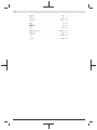 2
2
-
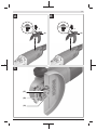 3
3
-
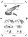 4
4
-
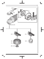 5
5
-
 6
6
-
 7
7
-
 8
8
-
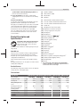 9
9
-
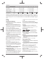 10
10
-
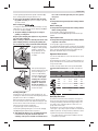 11
11
-
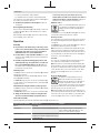 12
12
-
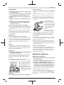 13
13
-
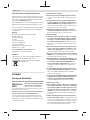 14
14
-
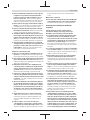 15
15
-
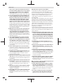 16
16
-
 17
17
-
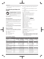 18
18
-
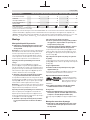 19
19
-
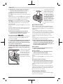 20
20
-
 21
21
-
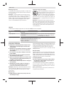 22
22
-
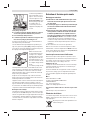 23
23
-
 24
24
-
 25
25
-
 26
26
-
 27
27
-
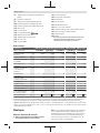 28
28
-
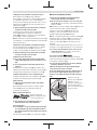 29
29
-
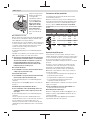 30
30
-
 31
31
-
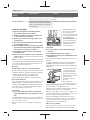 32
32
-
 33
33
-
 34
34
-
 35
35
-
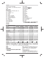 36
36
-
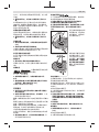 37
37
-
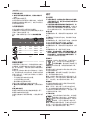 38
38
-
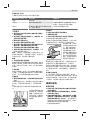 39
39
-
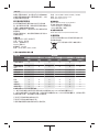 40
40
-
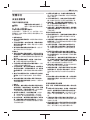 41
41
-
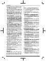 42
42
-
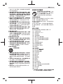 43
43
-
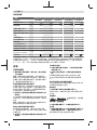 44
44
-
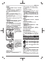 45
45
-
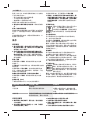 46
46
-
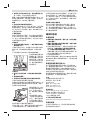 47
47
-
 48
48
-
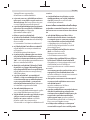 49
49
-
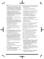 50
50
-
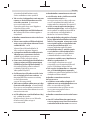 51
51
-
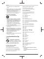 52
52
-
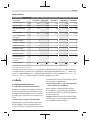 53
53
-
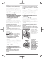 54
54
-
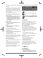 55
55
-
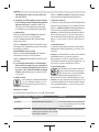 56
56
-
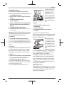 57
57
-
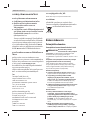 58
58
-
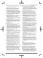 59
59
-
 60
60
-
 61
61
-
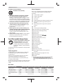 62
62
-
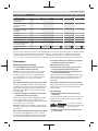 63
63
-
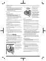 64
64
-
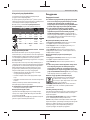 65
65
-
 66
66
-
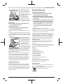 67
67
-
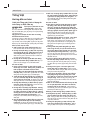 68
68
-
 69
69
-
 70
70
-
 71
71
-
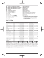 72
72
-
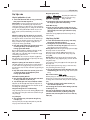 73
73
-
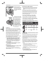 74
74
-
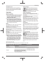 75
75
-
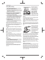 76
76
-
 77
77
-
 78
78
-
 79
79
-
 80
80
-
 81
81
-
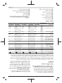 82
82
-
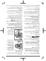 83
83
-
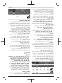 84
84
-
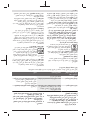 85
85
-
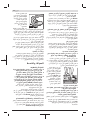 86
86
-
 87
87
-
 88
88
-
 89
89
-
 90
90
-
 91
91
-
 92
92
-
 93
93
-
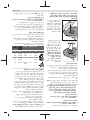 94
94
-
 95
95
-
 96
96
-
 97
97
-
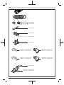 98
98
-
 99
99


Bosch 30-180 B Manual do usuário
- Categoria
- Rebarbadoras
- Tipo
- Manual do usuário
em outros idiomas
- français: Bosch 30-180 B Manuel utilisateur
- 日本語: Bosch 30-180 B ユーザーマニュアル