Makita LS0816F Manual do usuário
- Categoria
- Serras de esquadria
- Tipo
- Manual do usuário

LS0816F
EN Slide Compound Miter Saw INSTRUCTION MANUAL 13
FR Scie à Onglet Radiale MANUEL D’INSTRUCTIONS 27
DE Kapp- und Gehrungssäge BETRIEBSANLEITUNG 43
IT Troncatrice composita a slitta ISTRUZIONI PER L’USO 60
NL Schuifbare afkortverstekzaag GEBRUIKSAANWIJZING 77
ES Sierra de Inglete Telescópica MANUAL DE
INSTRUCCIONES 93
PT Serra de Esquadria c/ Braço
Telescópico MANUAL DE INSTRUÇÕES 109
EL
125
TR
Testere KULLANMA KILAVUZU 142

2
Fig.1
27
4
5
6
10
7
8
11
12 13 14 15 17 18 19
21
16
22
1
24
25
26 23
20
2
3
9
Fig.2

3
12
3
4
6
5
89
7
Fig.3
1
2
Fig.4
1
Fig.5
1
Fig.6

4
1
2
Fig.7
1
Fig.8
1
2
3
4
Fig.9
12
Fig.10
1
2
Fig.11
Fig.12
1 1
22
33
45
Fig.13

5
1
2
Fig.14
Fig.15
Fig.16
1
2
Fig.17
2
13
Fig.18
1
2
34
Fig.19

6
13
2
Fig.20
1
2
3
Fig.21
1
23
Fig.22
1
2
3
Fig.23
1
Fig.24

7
1
2
3
4
Fig.25
12
3
Fig.26
1
Fig.27
14
2356
Fig.28
12
3
Fig.29
1
3
4
2
Fig.30
12
3
Fig.31

8
14
2356
Fig.32
1
Fig.33
1
2
Fig.34
1
Fig.35
2
1
Fig.36
2
1
3
Fig.37
12
Fig.38
1
2
Fig.39

9
1
2
Fig.40
1
Fig.41
1
Fig.42
Fig.43

10
123
Fig.44
2
3
1
4
Fig.45
2
1
5
4
3
Fig.46
1
2
Fig.47
1
Fig.48
Fig.49
Fig.50
3
3
1
2
Fig.51

11
1
2
Fig.52
1
2
3
Fig.53
1
22
Fig.54
1
2
3
Fig.55
1
2
3
Fig.56
1
2
Fig.57
1
Fig.58

12
1
Fig.59
1
Fig.60

13 ENGLISH
ENGLISH (Original instructions)
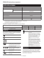
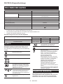
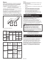
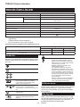
SPECIFICATIONS
Model: LS0816F
Blade diameter 216 mm
Hole diameter European countries 30 mm
Countries other than Europe 25.4 mm or 30 mm
Max. kerf thickness of the saw blade 2.8 mm
Max. miter angle Left 47°, Right 47°
Max. bevel angle Left 47°, Right 2°
5,000 min-1
476 mm x 705 mm x 521 mm
Net weight 13.9 kg
Safety class /II
without notice.
• Weight according to EPTA-Procedure 01/2014
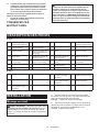
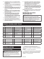
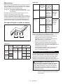
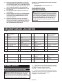
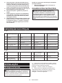
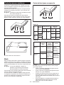
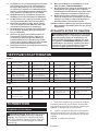
Cutting capacities (H x W) with ø 216 mm saw blade
Miter angle Bevel angle
45° (left) 0° 2° (right)
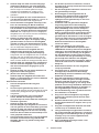
0° 36 mm x 305 mm 65 mm x 305 mm 60 mm x 305 mm
36 mm x 215 mm 65 mm x 215 mm -
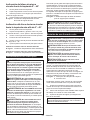
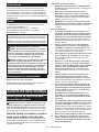
The followings show the symbols which may be used
for the equipment. Be sure that you understand their
meaning before use.
Read instruction manual.
DOUBLE INSULATION
Wear safety glasses.
holding the saw head down, after making
cuts, until the saw blade has come to a
complete stop.
-
riage fully and press down handle, then
push carriage toward the guide fence.
saw blade.
and blade guard properly.
Do not stare at operating lamp.
Only for EU countries
Due to the presence of hazardous compo-
nents in the equipment, used electrical and
electronic equipment may have a negative
impact on the environment and human health.
Do not dispose of electrical and electronic
appliances with household waste!
In accordance with the European Directive
on waste electrical and electronic equip-
ment and its adaptation to national law,
used electrical and electronic equipment
should be collected separately and
delivered to a separate collection point
for municipal waste, operating in accor-
dance with the environmental protection
regulations.
This is indicated by the symbol of the
crossed-out wheeled bin placed on the
equipment.
Intended use
The tool is intended for accurate straight and miter
cutting in wood. With appropriate saw blades, aluminum
can also be sawed. For details, according to the section
for OPERATION.
The tool should be connected only to a power supply of
the same voltage as indicated on the nameplate, and
can only be operated on single-phase AC supply. They
are double-insulated and can, therefore, also be used
from sockets without earth wire.

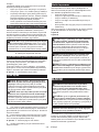
14 ENGLISH
Noise
The typical A-weighted noise level determined accord-
ing to EN62841-3-9:
Sound pressure level (LpA
Sound power level (LWA
NOTE:
been measured in accordance with a standard test
method and may be used for comparing one tool with
another.
NOTE:
may also be used in a preliminary assessment of
exposure.
WARNING: Wear ear protection.
WARNING: The noise emission during actual
processed.
WARNING: -
sures to protect the operator that are based on an
estimation of exposure in the actual conditions of
use (taking account of all parts of the operating
trigger time).
For European countries only
The Declarations of conformity are included in Annex A
to this instruction manual.
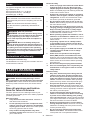
SAFETY WARNINGS
WARNING -
this power tool. Failure to follow all instructions listed
Save all warnings and instruc-
tions for future reference.
The term "power tool" in the warnings refers to your
1. Keep work area clean and well lit. Cluttered or
dark areas invite accidents.
2. Do not operate power tools in explosive atmo-
Power tools create sparks
which may ignite the dust or fumes.
3.
operating a power tool. Distractions can cause
you to lose control.
1. Power tool plugs must match the outlet. Never
adapter plugs with earthed (grounded) power
tools.
reduce risk of electric shock.
2.
refrigerators. There is an increased risk of elec-
tric shock if your body is earthed or grounded.
3. Do not expose power tools to rain or wet con-
ditions. Water entering a power tool will increase
the risk of electric shock.
4. Do not abuse the cord. Never use the cord for
or moving parts. Damaged or entangled cords
increase the risk of electric shock.
5.
extension cord suitable for outdoor use. Use of
a cord suitable for outdoor use reduces the risk of
electric shock.
6. If operating a power tool in a damp location
Use of an RCD reduces
the risk of electric shock.
7.
recommended.
8. Power tools can produce electromagnetic
However, users of pacemakers and other similar
medical devices should contact the maker of their
device and/or doctor for advice before operating
this power tool.
9. Do not touch the power plug with wet hands.
10.
manufacturer or his agent in order to avoid a
1.
common sense when operating a power tool.
-
ication. A moment of inattention while operating
2.
Protective equipment such
as a dust mask, non-skid safety shoes, hard hat or
hearing protection used for appropriate conditions
3. Prevent unintentional starting. Ensure the
Carrying power tools with
that have the switch on invites accidents.
4.
turning the power tool on. A wrench or a key left
attached to a rotating part of the power tool may
5. Do not overreach. Keep proper footing and
balance at all times. This enables better control
of the power tool in unexpected situations.

15 ENGLISH
6.
from moving parts.
long hair can be caught in moving parts.
7. If devices are provided for the connection of
Use of
dust collection can reduce dust-related hazards.
8.
A careless action
second.
9.
in Australia/New Zealand. In Australia/New
-
-
sons in the immediate working area.
Power tool use and care
1. Do not force the power tool. Use the correct
The correct
rate for which it was designed.
2. Do not use the power tool if the switch does
Any power tool that cannot
be controlled with the switch is dangerous and
must be repaired.
3. Disconnect the plug from the power source
-
tools. Such preventive safety measures reduce
the risk of starting the power tool accidentally.
4. Store idle power tools out of the reach of chil-
dren and do not allow persons unfamiliar with
the power tool or these instructions to operate
the power tool. Power tools are dangerous in the
hands of untrained users.
5. Maintain power tools and accessories. Check
-
Many accidents are caused by poorly maintained
power tools.
6. Keep cutting tools sharp and clean. Properly
maintained cutting tools with sharp cutting edges
are less likely to bind and are easier to control.
7.
-
ing into account the working conditions and
the work to be performed. Use of the power tool
result in a hazardous situation.
8.
clean and free from oil and grease. Slippery
handles and grasping surfaces do not allow for
safe handling and control of the tool in unexpected
situations.
9.
The entangle-
ment of cloth work gloves in the moving parts may
Service
1.
parts. This will ensure that the safety of the power
tool is maintained.
2. Follow instruction for lubricating and chang-
ing accessories.
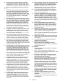
1. Mitre saws are intended to cut wood or wood-
-
Abrasive dust
causes moving parts such as the lower guard to
lower guard, the kerf insert and other plastic parts.
2. Use clamps to support the workpiece when-
ever possible. If supporting the workpiece
least 100 mm from either side of the saw blade.
Do not use this saw to cut pieces that are too
If your hand is placed too close to the saw blade,
contact.
3.
clamped or held against both the fence and the
table. Do not feed the workpiece into the blade
Unrestrained
or moving workpieces could be thrown at high
4. Push the saw through the workpiece. Do not
pull the saw through the workpiece. To make
press the saw head down and push the saw
through the workpiece. Cutting on the pull stroke
is likely to cause the saw blade to climb on top
of the workpiece and violently throw the blade
assembly towards the operator.
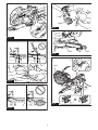
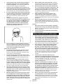
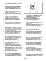
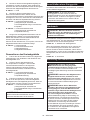
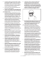
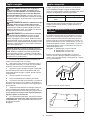
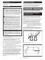
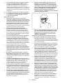
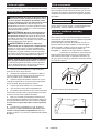
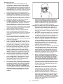
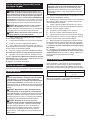
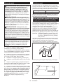
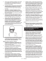
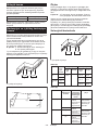
5.
of cutting either in front or behind the saw
blade. Supporting the workpiece "cross handed"
i.e. holding the workpiece to the right of the saw
blade with your left hand or vice versa is very
dangerous.
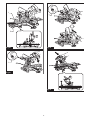
Fig.1

16 ENGLISH
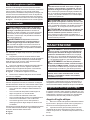
6. Do not reach behind the fence with either hand
closer than 100 mm from either side of the saw
reason while the blade is spinning. The proxim-
ity of the spinning saw blade to your hand may not
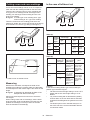
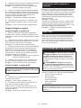
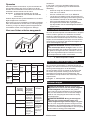
7.
the outside bowed face toward the fence.
the line of the cut. Bent or warped workpieces
can twist or shift and may cause binding on the
spinning saw blade while cutting. There should be
8. Do not use the saw until the table is clear of all
-
piece. Small debris or loose pieces of wood or
be thrown with high speed.
9. Stacked multi-
ple workpieces cannot be adequately clamped or
braced and may bind on the blade or shift during
cutting.
10. Ensure the mitre saw is mounted or placed on
A level
saw becoming unstable.
11.
workpiece and will not interfere with the blade
Without turning the tool
"ON" and with no workpiece on the table, move
the saw blade through a complete simulated cut to
assure there will be no interference or danger of
cutting the fence.
12. Provide adequate support such as table exten-
wider or longer than the table top. Workpieces
longer or wider than the mitre saw table can tip
workpiece tips, it can lift the lower guard or be
thrown by the spinning blade.
13. Do not use another person as a substitute for
a table extension or as additional support.
Unstable support for the workpiece can cause the
blade to bind or the workpiece to shift during the
cutting operation pulling you and the helper into
the spinning blade.
14.
saw blade.
and thrown violently.
15.
or tubing. Rods have a tendency to roll while
being cut, causing the blade to "bite" and pull the
work with your hand into the blade.
16. Let the blade reach full speed before contact-
ing the workpiece. This will reduce the risk of the
workpiece being thrown.
17.
parts to stop and disconnect the plug from
cause loss of control or damage to the mitre saw.
18.
the saw head down and wait for the blade to stop
Reaching with
your hand near the coasting blade is dangerous.
19.
proper guarding of the saw blade or guard operation
20.
a speed equal or higher than the speed marked
on the tool.
21. Do not use the saw to cut materials other than
22.
intended for wood and analogous materials.
Additional instructions
1. Make workshop kid proof with padlocks.
2. Never stand on the tool.
occur if the tool is tipped or if the cutting tool is
unintentionally contacted.
3. Never leave the tool running unattended. Turn
to a complete stop.
4.
Do not operate saw without guards in place.
Check blade guard for proper closing before each
use. Do not operate saw if blade guard does not
tie the blade guard into the open position.
5. Keep hands out of path of saw blade. Avoid
6.
full rear position after each crosscut operation.
7.
8.
Stopper pin or stopper lever which locks the saw
9.
damage before operation. Replace cracked or
pitch hardened on saw blades slows saw and
increases potential for kickback. Keep saw blade
-
sene. Never use gasoline to clean saw blade.
10.
occur. KICKBACK occurs when the saw
blade binds in the workpiece during a cutting
towards the operator. Loss of control and
do not continue to cut and release switch

17 ENGLISH
11.
12.
Damage to these parts could result in saw
blade breakage.
13.
secured so it will not move during operation.
Use the holes in the base to fasten the saw to a
stable work platform or bench. NEVER use tool
where operator positioning would be awkward.
14. Make sure the shaft lock is released before the
switch is turned on.
15. Be sure that the saw blade does not contact
the turn base in the lowest position.
16.
stopping.
17. Make sure the saw blade is not contacting the
workpiece before the switch is turned on.
18.
let it run for a while. Watch for vibration or
wobbling that could indicate poor installation
19. -
thing abnormal.
20. Do not attempt to lock the trigger in the "ON"
position.
21.
manual. Use of improper accessories such as
22.
be toxic. Take caution to prevent dust inhala-
tion and skin contact. Follow material supplier
1. Do not look in the light or see the source of
SAVE THESE INSTRUCTIONS.
WARNING:
with product (gained from repeated use) replace
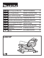
PARTS DESCRIPTION
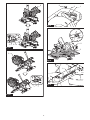
Fig.2
1
2Stopper arm 3Dust bag 4Thumb screw (for car-
5 6Bevel angle scale 7Slide pole 8Vertical vise
9Sliding fence 10
11 Guide fence 12 Sub base
13 Turn base 14 Miter angle scale 15 16 Kerf board
17
18 19 20 Dust collecting guard
21 Blade guard 22 Lamp 23 24 Switch trigger
25 Hole for padlock 26 27 Carry handle - -
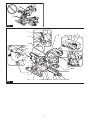
Fig.3
1Lamp switch 2Shaft lock 3-
4Stopper pin (for carriage
5Set plate 6Hex wrench 7
8
9Releasing button (for
- - - - - -
INSTALLATION
Bench mounting
WARNING: Ensure that the tool does not
move on the supporting surface. Movement of the
miter saw on the supporting surface while cutting may
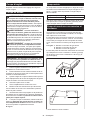
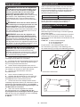
1. Fix the base to a level and stable surface, screw-
ing with the bolts. This helps to prevent from tipping and
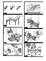
Fig.4: 1. Bolt 2. Mounting hole
2. -
-
face to keep the tool stable.
Fig.5: 1.

18 ENGLISH
FUNCTIONAL
DESCRIPTION
WARNING:
checking function on the tool.
and unplug the tool may result in serious personal
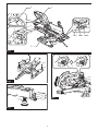
Handle lock
CAUTION:
releasing the stopper pin. Otherwise the handle
When the tool is shipped, the handle is locked in the
lowered position with the stopper pin. To unlock the
handle, pull the stopper pin while lowering the handle
slightly.
Fig.6: 1. Stopper pin
Slide lock
To allow the sliding movement of the carriage, loosen
thumb screw on the arm. To lock the sliding movement
of the carriage, move the carriage to your desired posi-
tion, and then tighten the thumb screw securely.
Fig.7: 1. Thumb screw 2. Arm
Blade guard
WARNING: Never defeat or remove the blade
guard or the spring which is attached to the
guard. An exposed circular saw blade as a result
of defeated guarding may result in serious personal
WARNING: Never use the tool if the blade
Operation of the tool with a damaged, faulty or
CAUTION:
in good condition for safe operation. Stop the
of the blade guard. Check to assure spring loaded
return action of guard.
When lowering the handle, the blade guard raises
automatically. The guard is spring loaded so it returns to
its original position when the cut is completed and the
handle is raised.
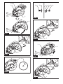
Fig.8: 1. Blade guard
Cleaning
If the transparent blade guard becomes dirty, or saw-
dust adheres to the transparent blade guard in such
a way that the circular saw blade and/or workpiece is
no longer easily visible, unplug the tool and clean the
guard carefully with a damp cloth. Do not use solvents
or any petroleum-based cleaners on the plastic guard
because this may cause damage to the guard.
Follow the step-by-step instructions listed on how to
prepare for cleaning.
1.
unplugged.
2. Turn the hex socket bolt counterclockwise using
the supplied hex wrench with holding the center cover.
3. Raise the blade guard and center cover.
4. When cleaning is complete, return the center
cover and tighten the hex socket bolt by performing the
steps above in reverse.
Fig.9: 1. Hex wrench 2. Hex socket bolt 3. Center
cover 4. Blade guard
WARNING: Do not remove spring holding
blade guard. If guard becomes damaged in course
of time or UV light exposure, contact a Makita ser-
vice center for replacement. DO NOT DEFEAT OR
REMOVE GUARD.
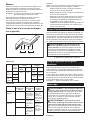
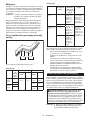
Positioning kerf boards
This tool is provided with the kerf boards in the turn
base to minimize tearing on the exit side of a cut. The
blade does not contact the kerf boards. Before use,
1. Make sure that the tool is unplugged. Then, loosen
kerf boards.
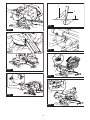
Fig.10: 1. Kerf board 2. Screw
2. Re-tighten them only to the extent that the kerf
boards can still be easily moved by hand.
3. Lower the handle fully, then lock the handle in the
lowered position with the stopper pin.
4. Loosen thumb screw on the arm which secures
the sliding movement of the carriage.
Pull the carriage toward you fully.
Fig.11: 1. Thumb screw 2. Arm
5.
sides of the saw blade teeth.
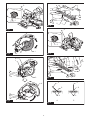
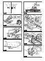
Fig.12
Fig.13: 1. Circular saw blade 2. Blade teeth 3. Kerf
board 4. Left bevel cut 5. Straight cut
6.
7. Slide the carriage to the position between the front
boards so that they are close to the
sides of the saw blade teeth.
8.
9. Push the carriage toward the guide fences fully
the sides of the saw blade teeth.

19 ENGLISH
10.
11. Release the stopper pin for handle lock and raise
the handle. Then tighten all the screws securely.
NOTICE:
Correct
support of the workpiece and minimizing workpiece
tear out.
Maintaining maximum cutting
cutting capacity for a 216 mm circular saw blade.
When installing a new circular saw blade, always check
the lower limit position of the circular saw blade, and if
1. Unplug the tool. Then, push the carriage toward
the guide fence fully and lower the handle completely.
2.
below the cross section of the guide fence and the top
surface of the turn base.
Fig.14: 1.2. Guide fence
Fig.15
3. Rotate the circular saw blade by hand while
holding the handle all the way down to be sure that
the circular saw blade does not contact any part of the
necessary.
WARNING: After installing a new circular saw
sure that the circular saw blade does not contact
If the circular saw blade con-
tacts with the base, it may cause kickback and result
Fig.16
Stopper arm
The lower limit position of the saw blade can be easily
the stopper arm in the direction of the arrow as shown in the
at the desired position when lowering the handle fully.
Fig.17: 1. Stopper arm 2.
CAUTION:
NOTICE:
Rotate the grip counterclockwise to unlock the turn
base. Turn the grip while holding up the lock lever to
move the turn base. Align the pointer with your desired
angle in the miter angle scale then tighten the grip.
Fig.18: 1. Lock lever 2. Grip 3. Pointer
Positive stop function
This miter saw employs positive stop function. You can
set 0°, 15°, 22.5°, 31.6°, and 45° right/left miter angle
quickly. To use this function, move the turn base close
to your desired positive stop angle while holding up the
lock lever. Then release the lock lever and move the
turn base to your desired positive stop angle until the
turn base is locked.
CAUTION:
clockwise.
NOTICE:
NOTICE:
NOTICE:
explained in the section for positioning kerf
boards.
NOTICE: Do not tighten the lever too hard. Doing
-
nism of the bevel angle.
Tilting the circular saw blade to the
left 0° - 45°
1. Rotate the lever counterclockwise.
2. Hold the handle and tilt the carriage to the left.
3. Align the pointer with your desired angle in the
bevel angle scale.
4. Tighten the lever clockwise to secure the arm.
Fig.19: 1. Lever 2. Handle 3. Pointer 4. Bevel angle
scale
the left 0° - 45°
1. Rotate the lever counterclockwise.
2. Hold the handle and set the carriage at 0° for right
2° side, or 45° for left 47° side.
3. Tilt the carriage slightly to opposite side.
4. Push the releasing button.
5. Tilt the carriage to the desired position beyond the
range 0° - 45°.
6. Tighten the lever clockwise to secure the arm.
When tilting the carriage to the right 2°
Fig.20: 1. Lever 2. Handle 3. Releasing button
When tilting the carriage to the left 47°
Fig.21: 1. Lever 2. Handle 3. Releasing button

20 ENGLISH
Switch action
WARNING:
-
when released. Do not pull the switch trigger hard
cause switch breakage. Operating a tool with a
switch that does not actuate properly can lead to loss
WARNING:
operative switch trigger. Any tool with an inoper-
ative switch is HIGHLY DANGEROUS and must be
repaired before further usage or serious personal
WARNING:
A switch with
WARNING: NEVER use the tool if it runs when
-
A switch in need of repair
may result in unintentional operation and serious
for proper repairs BEFORE further usage.
To prevent the switch trigger from being accidentally
Release the switch trigger to stop.
A hole is provided in the switch trigger for insertion of a
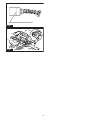
Fig.22: 1. Switch trigger 2.3. Hole
for padlock
WARNING: Do not use a lock with a shank
A
smaller shank or cable may not properly lock the tool
Casting a cutting line
CAUTION: The lamp is not a rainproof. Do not
wash the lamp in water or use it in a rain or a wet
area. Such a conduct can cause an electric shock
and fume.
CAUTION: Do not touch the lens of the lamp
This may cause burns.
CAUTION:
time to it.
CAUTION: Do not look in the light or see the
The LED lamp casts a light over the circular saw blade,
and a shadow of the saw blade falls onto a workpiece
serving as a calibration-free cutting line indicator. Press
the lamp switch to shed a light. A line appears in which
the saw blade will meet the surface of the workpiece,
becoming deepened as the saw blade gets lowered.
Fig.23: 1. Lamp switch 2. Lamp 3. Cutting line
penciled on a workpiece.
1. Hold the handle and lower the circular saw blade
so a dense shadow of the saw blade is thrown against a
workpiece.
2.
the shadowed cutting line.
3.
necessary.
NOTE:
Otherwise the lamp stays hot.
ASSEMBLY
WARNING:
the tool.
Hex wrench storage
When not in use, store the hex wrench as shown in the
Fig.24: 1. Hex wrench
Installing or removing circular saw
blade
WARNING:
installing the circular saw blade. Accidental startup
WARNING: -
vided to remove and install the circular saw blade.
Failure to use the wrench may result in overtightening
WARNING: Never use or substitute the parts
which are not supplied with this tool. Using such
WARNING: After installing the circular
installed. Loose attachment of the circular saw blade
Common preparations for installing
or removing the circular saw blade
1. Unlock the carriage by pulling the stopper pin,
then move the carriage to the raised position.
2. Loosen the hex socket bolt holding the center
cover using the hex wrench. Then, raise the blade
guard and center cover.
Fig.25: 1. Hex wrench 2. Hex socket bolt 3. Center
cover 4. Blade guard
A página está carregando...
A página está carregando...
A página está carregando...
A página está carregando...
A página está carregando...
A página está carregando...
A página está carregando...
A página está carregando...
A página está carregando...
A página está carregando...
A página está carregando...
A página está carregando...
A página está carregando...
A página está carregando...
A página está carregando...
A página está carregando...
A página está carregando...
A página está carregando...
A página está carregando...
A página está carregando...
A página está carregando...
A página está carregando...
A página está carregando...
A página está carregando...
A página está carregando...
A página está carregando...
A página está carregando...
A página está carregando...
A página está carregando...
A página está carregando...
A página está carregando...
A página está carregando...
A página está carregando...
A página está carregando...
A página está carregando...
A página está carregando...
A página está carregando...
A página está carregando...
A página está carregando...
A página está carregando...
A página está carregando...
A página está carregando...
A página está carregando...
A página está carregando...
A página está carregando...
A página está carregando...
A página está carregando...
A página está carregando...
A página está carregando...
A página está carregando...
A página está carregando...
A página está carregando...
A página está carregando...
A página está carregando...
A página está carregando...
A página está carregando...
A página está carregando...
A página está carregando...
A página está carregando...
A página está carregando...
A página está carregando...
A página está carregando...
A página está carregando...
A página está carregando...
A página está carregando...
A página está carregando...
A página está carregando...
A página está carregando...
A página está carregando...
A página está carregando...
A página está carregando...
A página está carregando...
A página está carregando...
A página está carregando...
A página está carregando...
A página está carregando...
A página está carregando...
A página está carregando...
A página está carregando...
A página está carregando...
A página está carregando...
A página está carregando...
A página está carregando...
A página está carregando...
A página está carregando...
A página está carregando...
A página está carregando...
A página está carregando...
A página está carregando...
A página está carregando...
A página está carregando...
A página está carregando...
A página está carregando...
A página está carregando...
A página está carregando...
A página está carregando...
A página está carregando...
A página está carregando...
A página está carregando...
A página está carregando...
A página está carregando...
A página está carregando...
A página está carregando...
A página está carregando...
A página está carregando...
A página está carregando...
A página está carregando...
A página está carregando...
A página está carregando...
A página está carregando...
A página está carregando...
A página está carregando...
A página está carregando...
A página está carregando...
A página está carregando...
A página está carregando...
A página está carregando...
A página está carregando...
A página está carregando...
A página está carregando...
A página está carregando...
A página está carregando...
A página está carregando...
A página está carregando...
A página está carregando...
A página está carregando...
A página está carregando...
A página está carregando...
A página está carregando...
A página está carregando...
A página está carregando...
A página está carregando...
A página está carregando...
A página está carregando...
A página está carregando...
A página está carregando...
-
 1
1
-
 2
2
-
 3
3
-
 4
4
-
 5
5
-
 6
6
-
 7
7
-
 8
8
-
 9
9
-
 10
10
-
 11
11
-
 12
12
-
 13
13
-
 14
14
-
 15
15
-
 16
16
-
 17
17
-
 18
18
-
 19
19
-
 20
20
-
 21
21
-
 22
22
-
 23
23
-
 24
24
-
 25
25
-
 26
26
-
 27
27
-
 28
28
-
 29
29
-
 30
30
-
 31
31
-
 32
32
-
 33
33
-
 34
34
-
 35
35
-
 36
36
-
 37
37
-
 38
38
-
 39
39
-
 40
40
-
 41
41
-
 42
42
-
 43
43
-
 44
44
-
 45
45
-
 46
46
-
 47
47
-
 48
48
-
 49
49
-
 50
50
-
 51
51
-
 52
52
-
 53
53
-
 54
54
-
 55
55
-
 56
56
-
 57
57
-
 58
58
-
 59
59
-
 60
60
-
 61
61
-
 62
62
-
 63
63
-
 64
64
-
 65
65
-
 66
66
-
 67
67
-
 68
68
-
 69
69
-
 70
70
-
 71
71
-
 72
72
-
 73
73
-
 74
74
-
 75
75
-
 76
76
-
 77
77
-
 78
78
-
 79
79
-
 80
80
-
 81
81
-
 82
82
-
 83
83
-
 84
84
-
 85
85
-
 86
86
-
 87
87
-
 88
88
-
 89
89
-
 90
90
-
 91
91
-
 92
92
-
 93
93
-
 94
94
-
 95
95
-
 96
96
-
 97
97
-
 98
98
-
 99
99
-
 100
100
-
 101
101
-
 102
102
-
 103
103
-
 104
104
-
 105
105
-
 106
106
-
 107
107
-
 108
108
-
 109
109
-
 110
110
-
 111
111
-
 112
112
-
 113
113
-
 114
114
-
 115
115
-
 116
116
-
 117
117
-
 118
118
-
 119
119
-
 120
120
-
 121
121
-
 122
122
-
 123
123
-
 124
124
-
 125
125
-
 126
126
-
 127
127
-
 128
128
-
 129
129
-
 130
130
-
 131
131
-
 132
132
-
 133
133
-
 134
134
-
 135
135
-
 136
136
-
 137
137
-
 138
138
-
 139
139
-
 140
140
-
 141
141
-
 142
142
-
 143
143
-
 144
144
-
 145
145
-
 146
146
-
 147
147
-
 148
148
-
 149
149
-
 150
150
-
 151
151
-
 152
152
-
 153
153
-
 154
154
-
 155
155
-
 156
156


Makita LS0816F Manual do usuário
- Categoria
- Serras de esquadria
- Tipo
- Manual do usuário
em outras línguas
- español: Makita LS0816F Manual de usuario
- français: Makita LS0816F Manuel utilisateur
- italiano: Makita LS0816F Manuale utente
- Nederlands: Makita LS0816F Handleiding
- Deutsch: Makita LS0816F Benutzerhandbuch
- Türkçe: Makita LS0816F Kullanım kılavuzu