Dialight UL ProSite LED Floodlight Guia de instalação
- Tipo
- Guia de instalação

9100FLM000900 REV E
Page 1 of 10
ProSite Floodlight for UL 1598/1598A
Dialight, 1501 Route 34 South, Farmingdale, NJ, USA 07727
Tel: +1 732 919 3119 Fax: +1 732 751 5778 www.dialight.com
Important Information
These instructions contain safety information, read and follow them carefully. Dialight will not accept any responsibility
for
injury, damage or loss which may occur due to incorrect installation, operation or maintenance.
Installation/Operation
Instructions
Language
Page Number
English
3
Note: Save these instructions for future use.

9100FLM000900 REV E
Page 2 of 10
ProSite Floodlight for UL 1598/1598A
Dialight, 1501 Route 34 South, Farmingdale, NJ, USA 07727
Tel: +1 732 919 3119 Fax: +1 732 751 5778 www.dialight.com
WARNING: INSTALLATION & SECONDARY RETENTION.
The use of this product without proper installation and inspections, including secondary safety retention/securing/netting, could
cause severe injury or death.
Dialight recommends that all installations should use secondary retention and/or safety netting (appropriate to the installation
environment) where applicable. It is the exclusive responsibility of the contractor, installer and/or end customer to: (a) determine
the suitability of the product for its intended application; and, (b) ensure that the product is installed safely (with secondary retention
and/or safety netting where appropriate) and in compliance with all applicable laws and regulations. To the extent permissible
under the relevant law, Dialight disclaims all responsibility for personal injury and/or other damage resulting from any dislodgement
or other dislocation of this product.
ADVERTENCIA: INSTALACIÓN Y SISTEMA SECUNDARIO DE SUJECIÓN.
Usar este producto sin haberlo instalado e inspeccionado correctamente, lo que incluye usar sistemas secundarios de
retención/sujeción/redes, podría ocasionar lesiones graves o la muerte.
Dialight recomienda que en todas las instalaciones se utilice un sistema secundario de retención o una red de seguridad
(apropiados para el lugar de la instalación), según corresponda. Será responsabilidad exclusiva del contratista, el instalador o el
cliente final encargarse de lo siguiente: a) determinar si el producto es apto para el uso previsto; y b) asegurarse de que el producto
se instale de manera segura (usando un sistema secundario de retención o una red de seguridad, si corresponde) y de conformidad
con todas las leyes y disposiciones aplicables. En la máxima medida autorizada por la legislación pertinente, Dialight no será
responsable por ninguna lesión personal u otros daños que se produzcan a raíz de cualquier caída o desplazamiento de este
producto.
WARNUNG: INSTALLATION UND ZWEITE ABHÄNGUNG.
Die Verwendung dieses Produkts ohne ordnungsgemäße Installation und Inspektionen, einschließlich einer zweiten Abhängung/eines
Sicherheitsnetzes, könnte zu schweren Verletzungen oder Tod führen.
Dialight empfiehlt bei allen Installationen die Verwendung einer zweiten Abhängung und/oder eines Sicherheitsnetzes
(entsprechend der Installationsumgebung). Es ist die ausschließliche Verantwortlichkeit des Vertragsnehmers, Monteurs und/oder
Endkunden: (a) die Eignung des Produkts für seinen vorgesehenen Nutzungszweck zu bestimmen und (b) sicherzustellen, dass das
Produkt sicher (mit ggf. zweiter Abhängung und/oder einem Sicherheitsnetz) und gemäß allen geltenden Gesetzen und Vorschriften
montiert wird. Soweit gemäß dem geltenden Gesetz erlaubt, schließt Dialight jegliche Haftung für Körperverletzung und/oder andere
Schäden aufgrund einer Entfernung oder anderen Positionsänderung dieses Produkts aus.
AVERTISSEMENT : INSTALLATION ET FIXATION SECONDAIRE.
L’utilisation de ce produit sans une installation et des inspections en bonne et due forme, notamment la sécurisation/ la fixation de
sécurité secondaires/ l’installation d’une grille en acier tissée de sécurité, peut entraîner des blessures graves voire la mort.
Dialight recommande que toutes les installations soient pourvues d’une fixation secondaire ou d’une grille en acier tissée de sécurité
(adaptées à l’environnement de l’installation) dans la mesure du possible. Il va de la responsabilité exclusive de l’entrepreneur, de
l’installateur ou du client final de : (a) déterminer si le produit est adapté à son usage prévu et (b) assurer que le produit est installé
de manière sûre (avec une fixation secondaire et/ou une grille en acier tissée de sécurité le cas échéant) et en conformité avec la
loi et les normes en vigueur. Dans la mesure permise par la loi en vigueur, Dialight n’assumera aucune responsabilité en cas de
blessure sur la personne ou autre dommage résultant du déboîtement ou de toute autre dislocation de ce produit.
AVISO: INSTALAÇÃO E RETENÇÃO SECUNDÁRIA.
O uso deste produto sem a instalação e inspeções adequadas, incluindo retenção/fixação secundárias e/ou redes de segurança,
pode provocar ferimentos sérios ou morte.
A Dialight recomenda que todas as instalações utilizem retenção secundária e/ou redes de segurança (apropriadas ao ambiente
da instalação) sempre que aplicável. É responsabilidade exclusiva da empreiteira, instaladora e/ou do cliente final: (a) determinar
a adequabilidade deste produto para a aplicação pretendida; e, (b) assegurar que o produto seja instalado de maneira segura
(com retenção secundária e/ou rede de segurança sempre que apropriado) e em conformidade com todas as leis e
regulamentações aplicáveis. Dentro dos limites permitidos pela legislação pertinente, a Dialight se exime de toda responsabilidade
por ferimentos pessoais e/ou outros danos resultantes do desalojamento ou de outro deslocamento deste produto.

9100FLM000900 REV E
Page 3 of 10
ProSite Floodlight for UL 1598/1598A
Dialight, 1501 Route 34 South, Farmingdale, NJ, USA 07727
Tel: +1 732 919 3119 Fax: +1 732 751 5778 www.dialight.com
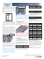
NOTE: Watertight fittings are required to be
used on this luminaire.
Equipment Application
This product can be used inside or outside to
illuminate areas in an industrial location.
WARNING: Please ensure the application
structure can handle the weight of the
luminaire. Dialight is not responsible for any
damages to the application structure or the
luminaire when mounted improperly.
Installation
Ensure that the mains voltage supply is
disconnected before connecting the
luminaire. Install the equipment in
accordance with the manufacturer’s
instructions as well as any other applicable
electric codes.
Always transport and store the equipment in
its original packaging and keep in a dry
location. When unpacking check for any
cracks or damage in the housing or lens. If in
doubt, do not install.
When assembling the cable entries for the
mains connection, always observe the
manufacturer’s specifications for the glands
used. Unused cable entries must be closed
and sealed by a certified blanking plug.
NOTE: The addition of cable glands, dust
caps, electrical plugs, or occupancy sensors
may change the IP rating of this luminaire.
WARNING: Do not over tighten as the
protection rating may be compromised.
Always refer to the gland manufacturer’s
data for torque settings.
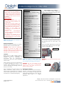
Mounting the Luminaire
This product can be mounted via bracket or
slip fitter. All bracket and slip fit mounting
options offer 7.5 degrees of adjustment with
angle indication labels present. The mast arm
mounting option offers +/- 5 degree
adjustment.
Bracket Models: F*U******(E/F)****
There are 2 bracket models, angled and
straight. See the Technical Diagrams section
for the mounting patterns.
Once mounted, the angle of the luminaire
can be adjusted by loosening the M8 Hex Bolt
on each side of the bracket. When loosening,
do not back bolt out more than 5 full
rotations.
When the desired angle has been achieved,
the bolts can be tighten to lock in the angle.
Torque: 15 ft-lbs [20.3 N-m]
WARNING: Do not loosen the Hex Nuts on the
bracket.
WARNING:
To avoid the risk of fire, explosion, or
electric shock, this product should be
installed, inspected, and maintained by
a qualified electrician in accordance
with all applicable electrical rules and
regulations.
Safety Instruction:
To avoid electric shock:
Be certain electrical power is OFF
before and during installation and
maintenance.
Make sure the supply voltage is the
same as the rated luminaire voltage.
The technical data indicated on the
LED luminaires are to be observed.
Changes of the design and
modifications to the LED luminaire are
not permitted.
Observe the national/regional
electrical safety rules and regulations
during installation.
The LEDs of this luminaire are not
replaceable; when the LEDs reach
their end of life, the whole luminaire
shall be replaced.
Technical Data:
Locations:
F*U*****(D/J)*****
IP-66/67 & NEMA 4X
F*U*****S*****
IP-66
Notice for UL 1598/1598A Models:
Outside Type (Salt Water)
Suitable for Wet Locations
Convient aux Emplacements Mouillés
Temperature Range:
F1U****(B/C/E/F)******
F2U****(F/H/L)******
-40°C to +65°C [-25°F to +149°F]
F2U****(E/N)******
-40°C to +55°C [-25°F to +131°F]
Rated Input Voltage:
F*U***(2/8)*******
120-277 VAC 50/60 Hz or 120-250 VDC
F*U***(5/9)*******
347-480 VAC 50/60 Hz
Weight:
F1U***********
29.9 lbs [13.6 kg]
F2U******(E/F)****
F2U7*****T****
F2U4*****T****
F2UN*****T****
54.1 lbs [24.5 kg]
57.7 lbs [26.2 kg]
55.1 lbs [24.9 kg]
50.7 lbs [22.9 kg]
Impact Rating:
F*U4**********
IK-10
F*U7**********
IK-08
F*UN**********
F*UNJ*********
IK-10
IK-07
Cable Entries:
2x 3/4 -14 NPT
(Not used on Slip Fitter models)
Mast Arm Models : 1x 3/4 NPS
Dimensions:
See Technical Diagrams
Technical Data:
Power Consumption:
F1U***(2/8)B******
81 W
F1U***(2/8)C******
124 W
F1U***(2/8)E******
175 W
F1U***(2/8)F******
234 W
F2U***(2/8)F******
200 W
F2U***(2/8)H******
234 W
F2U***(2/8)L******
346 W
F2U***(2/8)N******
484 W
F1U***(5/9)B******
84 W
F1U***(5/9)C******
128 W
F1U***(5/9)E******
179 W
F1U***(5/9)F******
237 W
F2U***(5/9)F******
206 W
F2U***(5/9)H******
241 W
F2U***(5/9)L******
357 W
F2U***(5/9)N******
499 W
M8 Hex Bolts
Hex Nuts

9100FLM000900 REV E
Page 4 of 10
ProSite Floodlight for UL 1598/1598A
Dialight, 1501 Route 34 South, Farmingdale, NJ, USA 07727
Tel: +1 732 919 3119 Fax: +1 732 751 5778 www.dialight.com
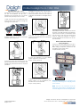
Slip Fitter Models: F1U******S****
All assembly pieces should be packed into
the box for installation. The slip fitter is
designed to be mounted over a 2” [51mm]
pole or 2.38” [60.5mm] max O.D. tenon.
1. Slide the pole base onto application pole
and feed source wire conductor through the
opening of the pole base.
2. Slightly tighten the set screws of the pole
base but do not torque yet.
3. Feed the source wire conductors into the
junction base mounted on the luminaire and
engage the junction base with the mounted
pole base.
4. Engage the captive pivot 7/16 hex bolt of
the junction base into the pole base to
secure the luminaire, but do not yet torque as
to still allow the luminaire to tilt for light pattern
aiming.
5. Tilt and turn the luminaire to desired
position on the application pole to illuminate
the desired area.
6. Once the luminaire is at the desired
position, tighten the pivot hex bolt.
Torque: 11 ft-lbs [14.9 N-m]
7. Tighten the set screws of the pole base to
secure position on the application pole.
Thread locker is recommended.
Torque: 5 ft-lbs [6.8 N-m]
Opening/Closing the Luminaire
This luminaire has 2 lids, a driver enclosure lid
and front access lid. Both lids are retained by
captive bolts and offer a combination head
style for ease of entry. The front access lid is
used for wiring the luminaire for bracket
models while slip fitter models do not use the
front access lid.
Bracket and Mast Arm Models:
F*U******(E/F/T)****
Loosen the 4x screws and remove the lid to
gain access to the terminal blocks for wiring.
When wiring is complete, reattach the lid,
and tighten screws back down.
Torque: 30 in-lbs [3.4 N-m]
NOTE: The lid is secured to the wiring box via
a lanyard; eliminating risk of dropping the lid
upon removal.
NOTE: The lid of the luminaire should be
oriented as shown above. The Dialight logo
should be aligned with the mounting bracket.
4x Captive Bolts
Pole Base
Junction Base
Cover

9100FLM000900 REV E
Page 5 of 10
ProSite Floodlight for UL 1598/1598A
Dialight, 1501 Route 34 South, Farmingdale, NJ, USA 07727
Tel: +1 732 919 3119 Fax: +1 732 751 5778 www.dialight.com
Slip Fitter Models: F1U******S****
Make proper connections inside the junction
base of the slip fitter and tuck any excess
wiring into the junction base. Assure none of
the wiring can be pinched when replacing
cover.
Install the cover and tighten the hardware
using the recommended torque to assure a
proper seal.
Torque: 1 in-lb [1.4 N-m]
Mast Arm Models: F2U******T****
Open the mast arm cover by loosening the
two captive 10-32 screws and pulling the
cover open. Loosen the four ½-13 bolts most
of the way to allow the pole to slide into the
housing.
Slide the fixture onto the pole at desired
incline. The middle “step” represents 0⁰ tilt.
The other steps represent +/-5⁰ tilt
respectively. Adjust to desired step as
needed. Tighten the four ½-13 bolts evenly
around the pole. Ensure that the clamp plate
remains parallel to the bottom of the mast
arm housing. A two axis bubble level is
included for mounting convenience.
Torque to 29-31 ft-lbs [39.3-42.1 N-m]
Feed mains cable through supplied cable
gland and into wire box.
Torque cable gland to 45-55in-lbs[5.2-6.2N-m]
After the fixture has been mounted, snap the
access cover closed and tighten the two 10-
32 captive screws to 30 in-lbs [3.4 N-m]
Note: If the access cover interferes with
mounting the fixture, press on the hinges
towards the top/front of the fixture. The cover
is spring-loaded and will snap out of place. To
reinstall after mounting, align the hinges on
the inclined springs and push towards the
back of the fixture. Cover should snap back
into place.
NOTE: The bracket that is factory installed is
suitable for 2” NPS poles. For 1.25” NPS or 1.5”
NPS poles, the second “W” shaped bracket
found in the box should be used by replacing
the factory-installed bracket. Be sure to reuse
the four ½-13 bolts, flat washers, and lock
washers.
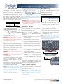
Asymmetric Wide Throw Models:
F2UNJ*********
After installation, remove the 4x rubber optic
protectors and 4x 10-32 screws. These can
then be discarded.
WARNING: The optic features on Asymmetric
Wide Throw models may be very sharp.
Appropriate actions should be taken when
handling the unit in order to prevent injury.
Damage to these sharp optical features will
result in degradation of the light pattern.
Electrical Connections
Bracket Models: F*U******(E/F)****
The terminal block is suitable for multi-
stranded or single core wires. The parameters
can be found in Technical Data.
Push Down Terminal Models: F*U********V**
Push down at the ‘cross point’, insert wire, and
release.
Conductor Range
Strip Length
0.5-4 mm² [20-12 AWG]
9 mm [0.35 in.]
Screw Down Terminal Models: F*U********U**
For input power terminal block, loosen
terminal screw, insert wire, and tighten screw.
Conductor Range
Strip Length
0.5-6 mm² [20-10 AWG]
10 mm [0.39 in.]
For dimming & Dali lines, push down at the
‘cross point’, insert wire, and release.
Conductor Range
Strip Length
0.5-4 mm² [20-12 AWG]
9 mm [0.35 in.]
Slip Fitter Models: F1U******S****
All slip fitter models contain lever nut
connectors inside the junction base to make
appropriate connections.
Conductor Range
Strip Length
0.5-4 mm² [20-12 AWG]
9 mm [0.35 in.]
Single Phase Connections
The connections are marked on the terminal
block or on a label and are presented in the
table below.
SYMBOL
COLOR
CONNECTION
120-277VAC
GREEN/
YELLOW
EARTH/
GROUND
N
WHITE
NEUTRAL
L
BLACK
LIVE
120-250VDC
GREEN/
YELLOW
EARTH/
GROUND
N
WHITE
-
L
BLACK
+
347-480VAC
GREEN/
YELLOW
EARTH/
GROUND
L2
RED
LIVE 2
L1
BLACK
LIVE 1
CONTROLS
DIM +
VIOLET
DIMMING +
DIM -
GREY
DIMMING -
DALI
ORANGE
OR YELLOW
DALI
0-10 VDC Dimming (If Applicable)
Dimming is controlled by means of a 0-10
VDC signal (to be provided by the installer) to
control the level of dimming. At 10 volts, the
output of the unit is 100%; at 0 volts, the output
will shut off. The DC dimming voltage should
not exceed 15 VDC. Increasing the voltage
from 10 VDC to 15 VDC will not result in
additional light output.
WARNING: Never connect the dimming wires
to the Hot/Live or Neutral supply wires.
4x 1/2 -13 bolts
“W” bracket orientation

9100FLM000900 REV E
Page 6 of 10
ProSite Floodlight for UL 1598/1598A
Dialight, 1501 Route 34 South, Farmingdale, NJ, USA 07727
Tel: +1 732 919 3119 Fax: +1 732 751 5778 www.dialight.com
Variable Voltage Control
An analog 0-10 V active dimmer may be
connected to the two wires to control the
light output of the fixture. Multiple lights may
be connected to the same dimmer, as long
as the maximum current rating of the dimmer
is not exceeded.
See table for current sinking capabilities of
the dimmer. Light output will vary
approximately linearly with control voltage,
with 10 V corresponding to 100% light output.
Part Number
Current
F1U***********
0.5 mA
F2U****(F/H)******
0.5 mA
F2U****(L/N)******
1.0 mA
NOTE: Simply shorting the two wires together
will cause the light to shut off.
WARNING: Improper installation, operation,
or maintenance of this luminaire may result in
the invalidation of the warranty, certificate,
or declaration of conformity.
DALI Control (If Applicable)
DALI is used to control/schedule and group
the luminaire. A DALI controller is to be
provided by the installer. The luminaire will not
provide a bus signal. A Bus power supply
should be used to provide a Bus signal
according to the DALI standard.
WARNING: Never connect the DALI wires to
the Hot/Live or Neutral supply wires.
WARNING: Do not connect the DALI wires to
the dimming wires.
For luminaires containing one power supply
[F1U*********** & F2U****(F/H)******], only one
DALI address will be assigned by the DALI
controller.
For luminaires containing two power supplies
[F2U****(L/N)******], two DALI addresses will
be assigned by the DALI controller.
NOTE: The DALI circuit in two power supply
luminaires are already internally wired as a
daisy chain to allow for commissioning and
discovery. The Bus wire needs to be
connected to the DALI terminal block
positions in the wiring compartment.
NOTE: Make sure luminaires containing two
power supplies are grouped and scheduled
together for the luminaire to function in the
correct manner.
WARNING: Improper installation, operation,
or maintenance of this luminaire may result in
the invalidation of the warranty, certificate,
or declaration of conformity.
Maintenance / Inspection
This LED luminaire should require a minimum
amount of maintenance. If any unforeseen
repairs are required, please contact Dialight
or its authorized representative.
Within the scope of maintenance or
inspection routine the following should be
included:
Protective hoses should be covering the
connection cables.
Cable entries must be free of corrosion.
The lens should be cleaned periodically as
needed to ensure continued photometric
performance. Clean the lens with a damp,
non-abrasive, lint free cloth. If not
sufficient, use mild soap or a liquid cleaner.
Inspect the luminaire to ensure that it is free
of any obstructions or contamination (i.e.
excessive dust build up). Clean with a non-
abrasive cloth if needed.
Perform visual mechanical and electrical
inspections on
a regular basis.
We
recommend routine checks to be made
on a yearly basis. Frequency of use and
environment should determine this.
It is recommended to follow an Electrical
Preventive Maintenance Program as
described in NFPA 70B: Recommended
Practice for Electrical Equipment.
Repairs / Overhaul / Modification
The equipment must be operated according
to the intended purpose in a perfect and
undamaged condition.
NOTE: Should the luminaire enclosure be
damaged, only a full luminaire replacement
will be permitted. In case of doubt, the
equipment should be returned to Dialight for
inspection/repair.
Disposal & Recycling
When the apparatus is disposed of, the
respective national regulations on waste
disposal should be observed.
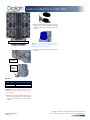
Secondary Retention Cable
Part Number
Description
H6XCAB60
Secondary Retention
Cable, Stainless Steel, 60”
H6XCAB72
Secondary Retention
Cable, Stainless Steel, 72”
1. Read and follow all instructions in the
installation manual provided with the
secondary retention cable.
2. Connect the safety cable to one of the
retention brackets on the luminaire.
3. When using a safety cable for secondary
retention, ensure minimum slack in the
cable installation. The slack should be no
greater than 1 ft. [0.3 m]
NOTE: Cable type, size, material, and
attachment method to meet customer
application and to be appropriate with all
local and regional regulations.
F1 Retention Bracket Locations
F1 Retention
Bracket

9100FLM000900 REV E
Page 7 of 10
ProSite Floodlight for UL 1598/1598A
Dialight, 1501 Route 34 South, Farmingdale, NJ, USA 07727
Tel: +1 732 919 3119 Fax: +1 732 751 5778 www.dialight.com
Photocell
Part Number
Description
SLPC01R
Photocell, 105-305V
SLPC02R
Photocell, 312-382V
SLPC03R
Photocell, 432-528V
WARNING: Photocell models are not rated to
120-250 VDC. Photocell models can only run
on AC voltage.
1. Remove the factory installed shorting cap
on the photocell receptacle. The shorting
cap can be removed by twisting and
pulling.
2. Collect and install the photocell provided.
The photocell can be installed by placing
it into the socket and twisting to lock the
position.
NOTE: The color of the photocell may be
different than what is shown; color is
dependent on photocell model.
3. Power the luminaire on and insure proper
function.
F2 Retention
Bracket
Slip Fitter
Base
Retention
Bracket
F2 Retention Bracket Locations

9100FLM000900 REV E
Page 8 of 10
ProSite Floodlight for UL 1598/1598A
Dialight, 1501 Route 34 South, Farmingdale, NJ, USA 07727
Tel: +1 732 919 3119 Fax: +1 732 751 5778 www.dialight.com
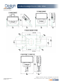
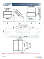
Technical Diagrams
Dimensions: in [mm]

9100FLM000900 REV E
Page 9 of 10
ProSite Floodlight for UL 1598/1598A
Dialight, 1501 Route 34 South, Farmingdale, NJ, USA 07727
Tel: +1 732 919 3119 Fax: +1 732 751 5778 www.dialight.com
Disclaimer: The information above represents a general version of the luminaire and is subject to change based on particular variations.

9100FLM000900 REV E
Page 10 of 10
ProSite Floodlight for UL 1598/1598A
Dialight, 1501 Route 34 South, Farmingdale, NJ, USA 07727
Tel: +1 732 919 3119 Fax: +1 732 751 5778 www.dialight.com
Official Statement
All statements, technical information, and recommendations contained herein are based on
information and tests that Dialight believes to be reliable. The accuracy or completeness
thereof is not guaranteed. In accordance with Dialight “Terms and Conditions of Sale” and
since conditions of use are outside our control, the purchaser should determine the suitability
of the product for his or her intended use and assumes all risk and liability whatsoever in
connection therewith.
Declaración Oficial
Todas las declaraciones, información técnica y recomendaciones aquí contenidas se basan
en información y pruebas que Dialight considera confiables. No se garantiza la exactitud ni
la exhaustividad de las mismas. Conforme a los “Términos y Condiciones de Venta” de
Dialight, y ya que las condiciones de uso están fuera de nuestro control, el comprador debera
determinar la idoneidad del producto para el uso que prevé darle y asume todos los riesgos
y responsabilidades de cualquier tipo en relación con ello.
Offizielle Erklärung
Alle hierin enthaltenen Angaben, technischen Daten und Empfehlungen basieren dem Wissen
von Dialight nach auf zuverlässigen Informationen und Tests. Deren Richtigkeit oder
Vollständigkeit wird daher nicht garantiert. Gemäß den „Verkaufsbedingungen und -
konditionen“ von Dialight und da die Nutzungsbedingungen sich unserer Kontrolle entziehen,
muss der Käufer die Eignung des Produkts für seinen beabsichtigten Nutzungszweck
bestimmen und alle mit im Zusammenhang stehenden Risiken und Haftungen übernehmen.
Déclaration officielle
Tous les chiffres, les données techniques et les recommandations contenus dans la présente
sont basés sur des données et des tests que Dialight considère comme fiables. L’exactitude et
l’exhaustivité de ces derniers ne sont donc pas garanties. En vertu des « Conditions générales
de vente » de Dialight et étant donné que les conditions d’utilisation de nos produits
échappent à tout contrôle de notre part, l’acheteur devra lui-même décider si le produit est
conforme à son usage prévu et engagera sa propre responsabilité quant aux risques associés
aux produits.
Declaração oficial
Todas as declarações, informações técnicas e recomendações contidas aqui baseiam-se
em informações e testes que a Dialight acredita serem confiáveis. A precisão ou atendimento
destes, porém, não é garantida. De acordo com os "Termos e Condições de Venda" da
Dialight, e uma vez que tais condições estão fora de nosso controle, o comprador deve
determinar a adequabilidade do produto para seu uso pretendido e assumir todos os riscos
e responsabilidades associados a isso.
-
 1
1
-
 2
2
-
 3
3
-
 4
4
-
 5
5
-
 6
6
-
 7
7
-
 8
8
-
 9
9
-
 10
10


