Husqvarna 18in. FS 513 Walk-Behind Concrete Saw Manual do proprietário
- Tipo
- Manual do proprietário

HUSQVARNA CONSTRUCTION PRODUCTS
FS 513
FS 520
FS 524
GB
ES
FR
Operator’s manual
Please read the operator’s manual carefully and make sure you under-
stand the instructions before using the machine.
Manuel d’utilisation
Lire attentivement et bien assimiler le manuel d’utilisation avant d’utiliser
la machine.
Manual de instrucciones
Lea detenidamente el manual de instrucciones y asegúrese de entender
su contenido antes de utilizar la máquina.

2

3
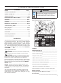
CONTENTS and INTRODUCTION
Contents
Section Page
Contents & Introduction................................................ 3
Symbols and Decals....................................................4-8
Safety Instructions.....................................................9-12
Parts Identication (What Is What).........................14-16
Assembly................................................................. 17-21
Operation ................................................................ 22-27
Maintenance & Lubrication ................................... 28-32
Trouble Shooting Guide............................................... 33
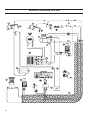
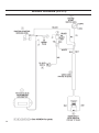
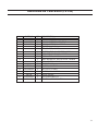
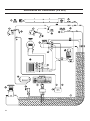
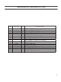
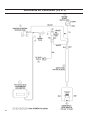
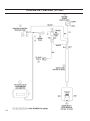
Wiring diagram........................................................ 34-38
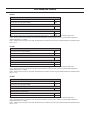
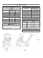
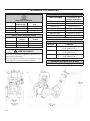
Technical Data......................................................... 39-40
Accessories.................................................................. 41
Conformity Certicates.................................................42
Contact Information.......................................................43
Introduction
Thank you for purchasing your new machine from Husqvar-
na Construction Products. We have provided important
safety messages in this manual and on the machine.
Please read these messages carefully. A safety message
alerts you to potential hazards that could hurt you or oth-
ers. Each safety message is preceded by a symbol or the
safety alert symbol ( ) and one of two words, WARNING,
or CAUTION.
These signal words mean:
WARNING: Indicates a hazardous situation which,
if not avoided COULD result in death or serious injury.
CAUTION: Indicates a hazardous situation, which,
if not avoided, COULD result in minor or moderate injury.
It may also be used to alert against unsafe practices.
Each message tells you what the hazard is, what can hap-
pen, and what you can do to avoid or reduce injury. Other
important messages are preceded by the word NOTICE.
NOTICE means:
NOTICE: Indicates a hazardous situation which, if not
avoided, could result in property damage. Your machine
or other property can be damaged if you don’t follow this
instruction.
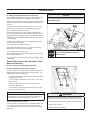
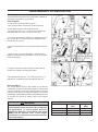
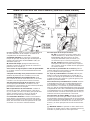
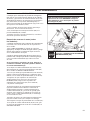
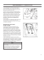
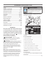
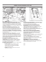
The safety labels should be periodically inspected and
cleaned by the user to maintain good legibility at a safe
viewing distance. If the label is worn, damaged, or is illeg-
ible, it should be replaced.
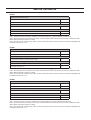
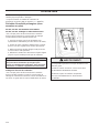
A. Model:______________________________________
B. Machine Serial No:____________________________
C. Year of Manufacture ___________________________
D. Mass of Machine (kg) __________________________
E. Engine Power (KW) ___________________________
F. Blade Diameter (mm) __________________________
G. Blade Speed (Revolutions / Minute) _______________
H. Electric Motor Voltage (If Equipped) _______________
I. Electric Motor Phase (If Equipped) _________________
J. Electric Motor Amperage (if Equipped) _____________
Other information not shown on machine serial plate:
Engine Serial No: _______________________________
See Engine Operation Manual for location.
Purchase Date:_________________________________
WARNING!
Before operating machine, read and under-
stand this entire operation manual & engine
operation manual supplied with engine.
Be familiar with machine before operation!
Model Identication: Record machine serial number
plate information below for future reference

4
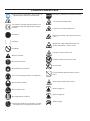
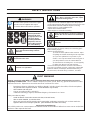
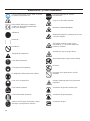
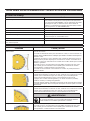
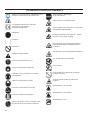
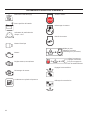
SYMBOLS and DECALS
Please read the instructions for use prior to
operating the machine for the rst time.
This symbol indicates that the machine is in
conformance with the applicable European
directive.
Mandatory
Indication
Prohibition
Warning Triangle
Wear Eye Protection
Wear Breathing Protection
The use of hearing protection is mandatory
Wear Head Protection
Wear Safety Shoes
Wear Appropriate Clothing
Remove the blade prior to Hoisting, Loading,
Unloading and Transporting the Machine.
Emergency Shutdown, Transmission Stop
Use In Well Ventilated Area
Do Not Use In Flammable Areas
Machinery Hazard, Keep hands and Feet
Clear.
Mufer Hot. May Cause Burns and / or
Ignition of Material. Avoid Contact.
Danger, Poison Exhaust Gas
No Non-working Personnel In Area
No Smoking
Do Not Operate Without Blade Guard in
Place
Always Keep All Guards In Place
Water Supply On
Water Supply Off
Water Supply

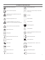
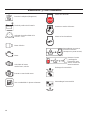
5
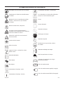
Blade Water Safety Switch
Engine Coolant Temperature
Keep Work Area Clean/Well Lit, Remove All
Safety Hazards
Dangerously High Noise Level
Pay Extreme Attention to The Care And
Protection Of The Machine Before Starting Up
Remove Tools From Area and Machine
Engine Oil Pressure
Oil Required
Dipstick, Maintain Proper Oil Level
Lubrication Point
High Speed
Low Speed
Electrical Switch-Off
Electrical Switch-On
Electrical Switch-Start
Repairs Are To Be Done By An Authorized
Dealer Only
Headlight
Diamond Blade
Blade Diameter
Blade Engagement
Pulley diameter
Number of Revolutions Per Minute, Rota-
tional Speed
Blade Flange Diameter
Blade Depth Stop
Cutting Depth Indicator – Depth of Cut
Parking Brake
Parking Brake Applied
Parking Brake Released
SYMBOLS and DECALS

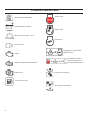
6
Machine Mass (Kilograms)
Positive Battery Terminal
Blade Depth Indicator – Zero
Electric Motor
Engine
Engine Speed Revolutions/Minute
Engine Start
Unleaded Fuel Only
SYMBOLS and DECALS
Engine Stop
Engine Start
Engine Run
Disengage to Start Engine
(Neutral Start)
Stop Engine and En-
gage Transmission to
Engage Parking Brake
Engage Transmission
Disengage Transmission

7
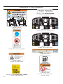
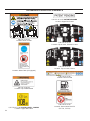
SYMBOLS and DECALS
P/N 542 19 05-89
Location: Depth Gauge
P/N 542 19 06-46 Local Service
Location: Side of Frame
P/N 542 19 07-33
Location: Front of Cowl
P/N 542 19 07-08 (2)
Location: Left and Right Side of Cowl
(FS 513 Only)
P/N 543 85 00-37
“Blade Guard Arrow (FS 524 - 600mm Only)
Top of Rear Blade Guard
(600 mm FS 520-FS 524 Only)
P/N 542 19 07-09 (2)
Location: Left and Right Side of Cowl
(FS 520 Only)
P/N 542 19 07-10 (2)
Location: Left and Right Side of Cowl
(FS 524 Only)
P/N 542 16 72-98 (2x)
Location: Left and Right Side of Blade Guard
(FS 513, 520 Only)

8
P/N 502 24 01-03
Location: Top of Cowl, FS 520, FS 524
P/N 542 19 05-93
Location: Rear of Cowl
P/N 542 16 90-65
Location: Top of Belt Guard
P/N 542 19 06-17
Location: Water Tank (If Equipped)
P/N 542 19 06-38
Location: Rear of Cowl
SYMBOLS and DECALS
P/N 543 04 57-88 SOUND LEVEL - 108dBA
Location: Upper RH Frame
P/N 502 24 01-01
Location: Top of Cowl, FS 513
P/N 542 16 12-35 PATENT PENDING
Location: Upper RH Frame
P/N 542 19 06-39
Location: Frame Near Fuel Fill
(FS 520, FS 524)

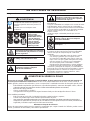
9
SAFETY INSTRUCTIONS
WARNING!
Before operating machine, read and under-
stand this entire operation manual & engine
operation manual supplied with engine.
Be familiar with machine before operation!
The working area must be completely
clear, well lit and all safety hazards
removed.
Any persons not involved in the work,
should leave the area.
WARNING! Take care when handling
fuel. Bear in mind the risk of re, explo-
sion and inhaling fumes.
General use
Never fuel machine in vicinity of sparks or
ames. Do not use machine in ammable
area.
Do not smoke while fueling or using the
machine.
Fuel Safety:
• Only store fuel in containers approved for the purpose.
• Only refuel machine with engine OFF. Never remove fuel
cap and ll the fuel tank while the engine is running.
• Always refuel in a well ventilated area.
• Never ll a fuel tank indoors.
• Allow engine to cool before refueling.
• Move machine 10 feet (3 meters) from refueling point
before starting engine.
• Never start the machine:
1) If fuel has been spilled on the machine. Wipe
off spillage and allow remaining fuel to evaporate.
2) If you have spilled fuel on yourself or your
clothes. Use soap and water to wash any part of
your body that has come in contact with fuel.
3) If the machine is leaking fuel. Check regularly
for leaks from the fuel cap and fuel lines.
• Store and transport machine and fuel so that there is
no risk of any leakage or fumes coming into contact with
sparks or ames, for example, electrical machinery or
electric motors, electrical relays / switches, or boilers.
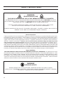
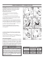
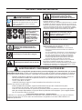
DUST WARNING
Cutting, especially when DRY cutting, generates dust that comes from the material being cut, which
frequently contains silica. Silica is a basic component of sand, quartz, brick clay, granite and numerous other
minerals and rocks. Exposure to excessive amount of such dust can cause:
• Respiratory diseases (affecting your ability to breath), including chronic bronchitis, silicosis and pulmo-
nary brosis from exposure to silica. These diseases may be fatal;
• Skin irritation and rash; and
• Cancer according to NTP* and IARC*
* National Toxicology Program, International Agency for Research on Cancer
Take precautionary steps
• Avoid inhalation of and skin contact with dust, mist and fumes;
• Wet cut when feasible, to minimize dust;
• Wear and ensure that all bystanders wear appropriate respiratory protection such as dust masks de-
signed to lter out microscopic particles. (See OSHA 29 CFR Part 1910.1200)
California Prop 65 Warning:
Use of this product can cause exposure to materials known to the State of California to cause cancer and/or birth
defects or other reproductive harm.
WARNING! Do not contact the tool when
machine is in operation.
Operator must wear
personal protective
equipment & cloth-
ing appropriate to the
work he is doing.
Personal protective
equipment, such as
hearing & eye protec-
tion, is mandatory.

10
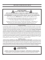
General Information
Carbon monoxide (CO) has the distinction of being one of the few commonly encountered industrial gasses that is
both highly toxic (poison) and odorless. When inhaled, CO acts as a chemical asphyxiant by preferentially combin-
ing with hemoglobin in the blood stream. As a result, the hemoglobin is not able to transport its normal amount of
oxygen, which results in under-oxygenation of tissues. Symptoms of low-level CO exposure include headaches,
dizziness, confusion, and nausea. However, loss of consciousness, permanent injury and death may result
from continued or more intense exposure. Because of the health hazards associated with CO inhalation, the Oc-
cupational Safety and Health Administration (OSHA) have imposed personal exposure limits. The OSHA exposure
limits, which are specied in the 29 CFR 1910.1000 (1998 Revision), allow for a 200 PPM Ceiling Limit and a TWA
of 35 PPM per 8-hour shift/40-hr workweek. It is strongly recommended that the OSHA 29 CFR 1910.1000 (Code
of Federal Regulations) be consulted for more information on exposure limits for various hazardous materials. If CO
Poisoning is suspected immediately remove the victim to fresh air and obtain emergency medical attention.
Proper Ventilation:
THIS SAW IS SHIPPED FROM THE FACTORY WITHOUT A CATALYTIC CONVERTER. It is important to be aware
that saws with catalytic converters reduce CO and hydrocarbon (HC) emissions. The exhaust still contains CO. If the
workspace is too conned or under-ventilated, CO may accumulate until it eventually exceeds OSHA limits. When
this happens, action must be taken to remove workers from areas of high concentration. Operators and work area
supervisors should take precautions to insure adequate ventilation of the workspace at all times. Carbon monoxide
detection monitors should be used to determine that adequate ventilation exists.
WARNING
POISON EXHAUST GAS
THIS SAW IS SHIPPED FROM THE FACTORY WITHOUT A CATALYTIC CONVERTER.
THE ENGINE PRODUCES CARBON MONOXIDE EXHAUST EMISSIONS AND IS NOT SAFE FOR USE IN
ENCLOSED AREAS. USE OF A CATALYTIC CONVERTER REDUCES THE CARBON MONOXIDE EXHAUST
EMISSIONS, BUT STILL IS NOT SAFE FOR USE IN ENCLOSED AREAS.
USE ONLY IN WELL-VENTILATED AREAS. WORK SITE AIR QUALITY MUST COMPLY WITH
OSHA 29 CFR 1910.1000 PER TABLE Z-1, LIMITS FOR AIR CONTAMINANTS.
MONITOR WORKSPACE AIR QUALITY TO INSURE COMPLIANCE. FAILURE TO COMPLY WILL RESULT IN
DANGER TO LIFE AND CAUSE PERMANENT INJURY OR DEATH.
WARNING
HEARING HAZARD
DURING NORMAL USE OF THIS MACHINE, OPERATOR MAY BE EXPOSED TO A NOISE
LEVEL EQUAL TO 85 dB (A) OR GREATER. TEMPORARY AND/OR PERMANENT DAMAGE TO HEARING
MAY RESULT. HEARING PROTECTION REQUIRED.
SAFETY INSTRUCTIONS

11
NOTES

12
DO Read this entire operator’s manual before operating this machine. Read and understand all warnings, instruc-
tions, controls, and symbol denitions contained in this manual, and on the machine.
DO always give a copy of this manual to the equipment user. If you need extra copies, call TOLL FREE
1-800-288-5040 in USA, or +1-913-928-1300 for International, or see “contact information” section of this
manual.
DO keep all guards in place and in good condition.
DO wear safety approved hearing, eye, head and respiratory protection.
DO read and understand all warnings and instructions on the machine.
DO keep all parts of your body away from the blade and all other moving parts.
DO know how to stop the machine quickly in case of emergency.
DO shut off the engine and allow it to cool before refueling or doing maintenance.
DO inspect the blade, anges and shafts for damage before installing the blade.
DO use the blade ange size shown for each blade size.
DO use only steel center diamond blades manufactured for use on concrete saws.
DO use only the blade anges supplied with the saw. Never use damaged or worn blade anges.
DO use only blades marked with a maximum operating speed greater than the blade shaft speed. Verify speed by
checking blade shaft rpm and pulley diameters and blade ange diameters.
DO verify saw drive conguration by checking blade shaft RPM, pulley diameters, and blade ange diameter.
DO read all safety materials and instructions that accompany any blade used with this machine.
DO inspect each blade carefully before using it. If there are any signs of damage or unusual wear, DO NOT USE
THE BLADE.
DO mount the blade solidly and rmly, Wrench tighten the arbor nut.
DO make sure the blade and anges are clean and free of dirt and debris before mounting the blade on the saw.
DO use the correct blade for the type of work being done. Check with blade manufacturer if you do not know if
blade is correct.
DO use caution and follow the instructions when loading and unloading the machine.
DO operate this machine only in well ventilated areas. Breathing Poison Exhaust Gas could result in death.
DO instruct bystanders on where to stand while the machine is in operation.
DO establish a training program for all operators of this machine.
DO clear the work area of unnecessary people. Never allow anyone to stand in front of or behind the blade while
the engine is running.
DO make sure the blade is not contacting anything before starting the engine.
DO use caution when lifting and transporting this machine.
DO always tie down the machine when transporting.
DO use caution and follow instructions when setting up or transporting the machine.
DO have all service performed by competent service personnel
DO verify the blade arbor hole matches the machine spindle before mounting the blade.
DO always check for buried hazards, such as electrical or gas lines before sawing. Always contact local utilities
before operation in unknown areas.
DO move the machine at least 10 feet (3 meters) from the fueling point before starting the engine and make sure
the fuel cap is on the machine and properly tightened.
DO lift machine only from specied lifting point.
DO clean the machine after each day’s use.
DO use the proper blade ange size for each blade size. Never use damaged or worn blade anges.
DO use caution when handling fuel.
DO only cut in a straight line, and only saw as deep as the job specications require.
SAFETY FIRST!
WARNINGS
DO’s AND DO NOT’s
WARNING: FAILURE TO COMPLY WITH THESE WARNINGS AND OPERATING
INSTRUCTIONS COULD RESULT IN DEATH OR SERIOUS BODILY INJURY.
SAFETY INSTRUCTIONS
DO

13
*****************
This saw was designed for certain applications only. DO NOT modify this saw or use for any application other
than for which it was designed. If you have any questions relative to its application, DO NOT use the saw until
you have written Husqvarna Construction Products and we have advised you.
Husqvarna Construction Products North America
17400 West 119th Street, Olathe, Kansas 66061 USA
DO NOT operate this machine unless you have read and understood this operator’s manual.
DO NOT operate this machine without the blade guard, or other protective guards in place.
DO NOT stand behind or in front of the blade path while the engine is running.
DO NOT leave this machine unattended while the engine is running.
DO NOT work on this machine while the engine is running.
DO NOT operate this machine when you are tired, fatigued or under the inuence of drugs or alcohol.
DO NOT use a wet blade without adequate water supply to the blade.
DO NOT exceed maximum blade speed shown for each blade size. Excessive speed could result in blade
breakage.
DO NOT operate the machine if you are uncertain of how to run the machine.
DO NOT use damaged equipment or blades.
DO NOT touch or try to stop a moving blade with your hand.
DO NOT cock, jam, wedge or twist the blade in a cut.
DO NOT transport a cutting machine with the blade mounted on the machine.
DO NOT use a blade that has been dropped or damaged.
DO NOT use carbide tipped blades.
DO NOT touch a dry cutting diamond blade immediately after use. These blades require several minutes to cool
after each cut.
DO NOT use damaged or worn blade anges.
DO NOT allow other persons to be near the machine when starting, refueling, or when the machine is in
operation.
DO NOT operate this machine in an enclosed area. Breathing Poison Exhaust Gas could result in death.
DO NOT operate this machine in the vicinity of anything that is ammable. Sparks could cause a re or an
explosion.
DO NOT allow blade exposure from the guard to be more than 180 degrees.
DO NOT operate this machine with the belt guards or blade guard removed.
DO NOT operate this machine unless you are specically trained for its operation.
DO NOT use a blade that has been over heated (Core has a bluish color).
DO NOT jam material into the blade.
DO NOT grind on the side of the blade.
DO NOT tow this machine behind a vehicle.
DO NOT operate this machine with the any guards or shields removed.
DO NOT cut deeper than 1” per pass with a dry blade. Step cut to achieve deeper cuts.
DO NOT operate this machine while under the inuence of drugs or alcohol.
SAFETY FIRST!
WARNINGS
DO’s AND DO NOT’s
WARNING: FAILURE TO COMPLY WITH THESE WARNINGS AND OPERATING
INSTRUCTIONS COULD RESULT IN DEATH OR SERIOUS BODILY INJURY.
DO NOT
SAFETY INSTRUCTIONS

14
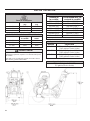
PARTS IDENTIFICATION (WHAT IS WHAT)
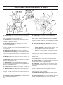
A. Front Pointer: Use to Guide machine in a straight line.
B. Guide Wheel: On Front Pointer (A). Align to cutting
line and Blade (H) to produce straight cuts.
C. Blade Guard: Covers Blade (H). Must always be in
place when operating machine! Note tool direction as
marked on guard with an arrow.
D. Blade Guard Front: Part of Blade Guard. Can be
raised to install Blade (H).
E. Blade Guard Rear Bolt: Holds Blade Guard (C) in
position. Must be removed and relocated if Blade Guard
(C) is moved.
F. Blade Guard Latch Plate: Covers Outer Flange (J).
G. Water Hose Disconnect (G): Connects Blade Guard
(C) to Water Control Valve (KK1, KK2) or Water Tank (P).
Can be used when Blade Guard (C) is mounted to left or
right side of machine
H. Blade: Tool that cuts asphalt or concrete material – not
included with machine.
I. Inner Flange: Arbor on which the Blade (H) is mounted.
Replace if Damaged or worn.
J. Outer Flange: Used to hold Blade (H) in position.
Contains Locking Pin (K) that must go through Blade (H).
Replace if damaged or worn.
K. Locking Pin: Holds Blade (H) in position. Replace if
Damaged or worn.
L. Blade Shaft Nut (L1 / L2): Holds Outer Flange (J) to
machine. Nut (L1) on right side of machine has Left Hand
threads. Nut (L2) (not shown) on left side of machine has
Right Hand threads.
M. Blade Arbor: Blade (H) mounts on this surface.
N. Water Tank / Lifting Point Support: Holds Water Tank
(P). Supports Lifting Point (O).
O. Lifting Point: Lift machine only from this point!
P. Water Tank (If Equipped): 25 Liter (6.6 U.S. Gallon)
water capacity. Fill only with water! Do not ll with gaso-
line or other ammable substances! Use only for dust
suppression when cutting dry. Use only with laser welded
(dry) Diamond Blades (H).
Q. Engine Starting Rope (FS 513 Only): Use to start
engine. See engine operation manual.
R. Fuel Tank: Fuel ll point.
FS 520 / FS 524: Located at rear of machine. Fuel
ll is located on Left hand side of fuel tank.
FS 513: Located on engine - See engine operation
manual.
S. Engine Air Cleaner (FS 513 Shown): Check daily.
Clean every four (4) hours if cutting in dusty conditions.
See engine operation manual and maintenance section of
this document.
T. Blade Shaft Wrench (27mm): Use for installing and
removing Blade (H). Store in Tool Compartment (BB).
U. Wrench (13mm): Use for many maintenance items on
machine. Store in Tool Compartment (BB).
V. Front Cover: Clips to Water Tank Support (N). Open
to turn Engine Start Switch (DD) ON (1) or OFF (0) [FS
513 Only].
W. Shaft Guard: Protects Inner Flange (I). Always in-
stalled on opposite side of frame to Blade Guard (C).
X. Depth Control Grease Fitting: Not Shown. See Main-
tenance section of this document.
Y. Blade Guard Mounting Spade: Holds Blade Guard
(C) in position.
Z. Engine Oil Dipstick: Use to check engine oil level (Not
Shown – See Operation Section of this document).

15
PARTS IDENTIFICATION (WHAT IS WHAT)
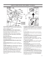
AA. Emergency Stop Switch: Depress Switch to STOP
engine in emergencies. Reset by pulling outward (pull up)
to allow re-starting of machine.
BB. Tool Compartment: Contains Operation Manual,
Parts List, & two wrenches (T & U) (13mm & 27mm).
Open by turning knob 180 degrees. Always return Opera-
tion Manual to this area for future reference.
CC. Engine Throttle: Controls Engine speed (RPM).
Push forward to increase engine speed. Pull backwards
to decrease engine speed. All sawing is done at maxi-
mum engine speed.
DD. Engine Start Switch:
FS 513: Located on engine, behind Front Cover (V). Must
be ON (1) to start engine. Use to turn engine OFF (“0”) in
non-emergency situations.
FS 520 & FS 524 (Electric Start): A key switch located
on lower left side of console. Turn key clockwise to start
engine.
EE. Blade Depth Control: Turn Counter-Clockwise to
raise Diamond Blade (H) and Clockwise to lower Diamond
Blade (H).
FF. Blade Depth Stop: To Lock Blade Depth Control (EE)
in position. Pull Blade Depth Stop toward rear of machine
and turn 90 degrees to lock in open position.
GG. Blade Depth Indicator: Shows cutting depth of Dia-
mond Blade (H) in centimeters (orange color) and inches
(white color). Operation: With engine OFF (“0”), lower
Diamond Blade (H) until in contacts the cutting surface.
Rotate Blade Depth Indicator to align “0” with arrows.
Raise Saw. When saw is lowered into cut, current cutting
depth is shown.
HH. Engine Tachometer (RPM): Shows engine speed in
revolutions per minute if engine is running. Shows total
operation time when engine is OFF (“0”). Total operation
time shown in minutes from 0-59 minutes, and hours for
60+ minutes.
II. – – –
JJ. Rear Handle: Operator position is behind machine
with both hands on Rear Handle. Handle is adjustable to
several positions.
KK1. Water Control Valve: Controls water ow to blade.
Located on Left side of machine, near Rear Handle (JJ).
Not used with the water tank (if equipped).
KK2. Blade Guard Water Control Valve: Controls the
water ow to the blade. Located on blade guard. Used
with water tank (if equipped).
LL. Belt Guard (Not Shown): Covers engine drive belt.
MM. Belt Drive Idler: Used to hold tension on Blade
Shaft Drive Belt.
NN. Oil Drain Hose: Use to remove oil from engine.
OO. Parking Brake (EU units): Used to hold machine
in parked position. With engine OFF (0), apply the brake
by moving Transmission Engagement Lever (PP), to the
“Engaged” position. Move lever to dis-engaged position
before starting engine!
PP. Transmission Engagement Lever: MUST BE in
rear (dis-engaged) position to start engine for FS 520 and
FS 524 (Neutral Start function). Push forward to engage
transmission. Push rearward to dis-engage transmission.
With transmission dis-engaged, machine can be moved
with engine turned OFF (0). See “OO. Parking Brake”
for additional information.

16
PARTS IDENTIFICATION (WHAT IS WHAT)
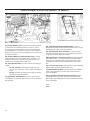
QQ. Travel Speed Lever: Controls ground travel speed
and direction of machine (forward or reverse). Move
lever forward to travel forward. Move lever rearward to
travel backward. Lever MUST be near “STOP” position
before moving Transmission Engagement Lever (PP) into
“Engaged” position.
RR. Starting Battery (FS 520, FS 524 Only): Located
behind lower access panel at the rear of machine. See
“Battery Maintenance” section of this document for in-
structions on charging and maintenance.
SS. Fuel Shut-Off Valve: Used to shut off fuel supply to
engine.
FS 520 / FS 524: Located behind lower access
door at rear of machine. Turn counter-clockwise to
close.
FS 513: Located on engine (see engine operation
manual for more information).
TT. Hydrostatic Transmission: Controls travel speed
and direction of machine. Maintenance free for the life of
the machine.
UU. Transmission Drive Tensioner Belt: Connects
Engine to Transmission Drive Belt Tensioner (VV). Check
periodically for wear on belt and sheaves.
V V. Transmission Drive Tensioner: Used to tension
Transmission Drive Belt (UU). See maintenance section
of this document for more information.
WW. Hydrostatic Transmission Belt: Drives Hydrostatic
Transmission (TT). Connects Transmission Drive Belt
Tensioner (VV) to Hydrostatic Transmission (TT). See
maintenance section of this document for more informa-
tion.
XX. Lower Access Panel: Open panel to expose Starting
Battery (RR) and Fuel Shut-Off Valve (SS).
YY. Bladeshaft Drive Belt: Connects Engine and Blade-
shaft. See maintenance section of this document for
more information.
ZZ. Hydrostatic Transmission Belt Tensioner: Spring
loaded idler used to tension Hydrostatic Transmission
Belt (WW). See maintenance section of this document for
more information.
AAA. --
BBB. --

17
ASSEMBLY
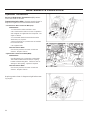
Assemble the following items before operating machine
for the rst time.
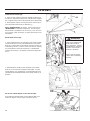
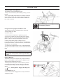
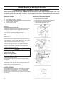
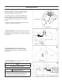
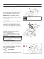
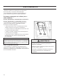
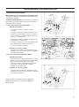
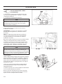
Re-Position Rear Handle (JJ): Rear Handle (JJ) is
shipped in storage position shown. It must be reposi-
tioned to use the machine.

18
ASSEMBLY
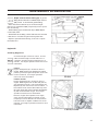
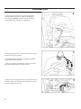
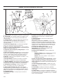
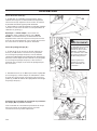
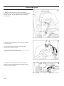
Install Front Pointer (A):
1. Using screws, washers and nuts installed in the Front
Pointer (A), install onto tube frame of Water Tank Support
(N). Adjust locking nuts to allow Pointer (A) to pivot freely.
2. Route pointer rope to avoid hot surfaces. Two loops in
rope allow attachment to Rear Handle (JJ).
Note: “Single Pointer” (A) shown. Some regions have
“Dual Pointer” as standard equipment. For all regions,
Dual Pointer is available as an accessory. See “accesso-
ries” section of this document, or spare parts list for more
information.
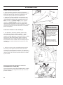
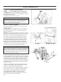
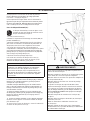
WARNING!
Blade Guard Latch Plate
(F) Must Be Installed
before operation. Failure
to Install before operating
machine could create a
Hazardous situation!
Always keep all guards
in place when operating
machine!
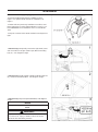
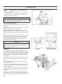
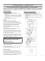
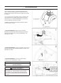
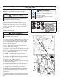
Re-Position Blade Depth Control Handle (EE):
Pull outward on Blade Depth Control Handle (EE) and
rotate 90 degrees until is snaps in position shown.
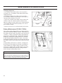
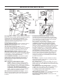
2. Reinstall three (3) M8 screws in Blade Guard Latch
Plate (F) as shown in the diagram at the right. Use the
13mm Wrench (U) (supplied) to securely tighten the four
(4) M8 bolts that hold the Blade Guard Latch Plate (F) in
position.
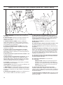
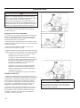
Blade Guard Front (D):
1. Using 13mm Wrench (U) provided, remove two (2) M8
screws located in front of and below Blade Guard Latch
Plate (F), and the M8 screw in Blade Guard Front (D) [as
indicated by arrows]. Lossen, but do not remove, remain-
ing screw Blade Guard Latch Plate (F). Rotate Blade
Guard Latch Plate (F), and Blade Guard Front (D) down-
ward.

19
ASSEMBLY
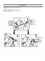
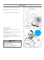
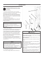
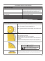
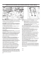
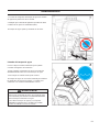
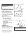
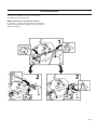
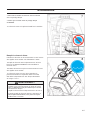
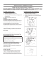
Install Water Tank (P) (if equipped):
• A factory installed water tank is available in some
regions. An optional water tank kit is available for all
regions.
• If water tank was previously installed on machine, read
these instructions to verify that installation is correct. Fol-
low all WARNINGS for installation and use of the Water
Tank.
• Verify the contents of the Water Tank Kit See Diagram at
right.
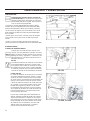
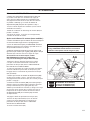
WARNING!
Torque NUT as specied, else failure of LIFTING EYE
(O) could occur. Injury or death could occur if LIFT-
ING EYE fails while lifting machine.
NOTICE
Torque Lifting Eye NUT to 83 N-m (61 lb-ft) mini-
mum.
1. FS 513 Only: Temporarily remove the right hand (same
side of machine as engine starter rope) NUT from Lifting
Eye (O). See diagram at right.
2. FS 513 Only: Install CLAMP supplied in Water Tank Kit
(P), and then reinstall the NUT. See diagram at right.
3. FS 513 Only: Torque as specied below, and diagram
at right.

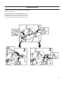
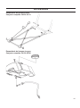
20
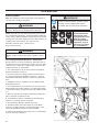
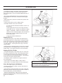
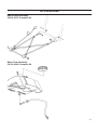
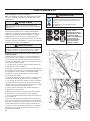
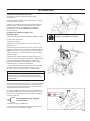
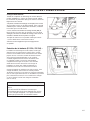
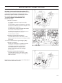
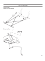
4. Position Water Tank, and route Water Tank Hose as
shown in Diagram at right (FS 513). FS 520 / FS 524 do
not use clamp shown in diagram.
ASSEMBLY
5. Align rear bar and recessed area at rear of water tank.
• Press down rmly on water tank so it snaps in position
onto rear bar.
• When properly installed, water tank should pivot freely
on rear bar.
6. Disconnect existing water hose from blade guard.
This is the water hose from water control valve mounted
on saw.
A página está carregando...
A página está carregando...
A página está carregando...
A página está carregando...
A página está carregando...
A página está carregando...
A página está carregando...
A página está carregando...
A página está carregando...
A página está carregando...
A página está carregando...
A página está carregando...
A página está carregando...
A página está carregando...
A página está carregando...
A página está carregando...
A página está carregando...
A página está carregando...
A página está carregando...
A página está carregando...
A página está carregando...
A página está carregando...
A página está carregando...
A página está carregando...
A página está carregando...
A página está carregando...
A página está carregando...
A página está carregando...
A página está carregando...
A página está carregando...
A página está carregando...
A página está carregando...
A página está carregando...
A página está carregando...
A página está carregando...
A página está carregando...
A página está carregando...
A página está carregando...
A página está carregando...
A página está carregando...
A página está carregando...
A página está carregando...
A página está carregando...
A página está carregando...
A página está carregando...
A página está carregando...
A página está carregando...
A página está carregando...
A página está carregando...
A página está carregando...
A página está carregando...
A página está carregando...
A página está carregando...
A página está carregando...
A página está carregando...
A página está carregando...
A página está carregando...
A página está carregando...
A página está carregando...
A página está carregando...
A página está carregando...
A página está carregando...
A página está carregando...
A página está carregando...
A página está carregando...
A página está carregando...
A página está carregando...
A página está carregando...
A página está carregando...
A página está carregando...
A página está carregando...
A página está carregando...
A página está carregando...
A página está carregando...
A página está carregando...
A página está carregando...
A página está carregando...
A página está carregando...
A página está carregando...
A página está carregando...
A página está carregando...
A página está carregando...
A página está carregando...
A página está carregando...
A página está carregando...
A página está carregando...
A página está carregando...
A página está carregando...
A página está carregando...
A página está carregando...
A página está carregando...
A página está carregando...
A página está carregando...
A página está carregando...
A página está carregando...
A página está carregando...
A página está carregando...
A página está carregando...
A página está carregando...
A página está carregando...
A página está carregando...
A página está carregando...
A página está carregando...
A página está carregando...
A página está carregando...
A página está carregando...
A página está carregando...
A página está carregando...
A página está carregando...
A página está carregando...
A página está carregando...
A página está carregando...
-
 1
1
-
 2
2
-
 3
3
-
 4
4
-
 5
5
-
 6
6
-
 7
7
-
 8
8
-
 9
9
-
 10
10
-
 11
11
-
 12
12
-
 13
13
-
 14
14
-
 15
15
-
 16
16
-
 17
17
-
 18
18
-
 19
19
-
 20
20
-
 21
21
-
 22
22
-
 23
23
-
 24
24
-
 25
25
-
 26
26
-
 27
27
-
 28
28
-
 29
29
-
 30
30
-
 31
31
-
 32
32
-
 33
33
-
 34
34
-
 35
35
-
 36
36
-
 37
37
-
 38
38
-
 39
39
-
 40
40
-
 41
41
-
 42
42
-
 43
43
-
 44
44
-
 45
45
-
 46
46
-
 47
47
-
 48
48
-
 49
49
-
 50
50
-
 51
51
-
 52
52
-
 53
53
-
 54
54
-
 55
55
-
 56
56
-
 57
57
-
 58
58
-
 59
59
-
 60
60
-
 61
61
-
 62
62
-
 63
63
-
 64
64
-
 65
65
-
 66
66
-
 67
67
-
 68
68
-
 69
69
-
 70
70
-
 71
71
-
 72
72
-
 73
73
-
 74
74
-
 75
75
-
 76
76
-
 77
77
-
 78
78
-
 79
79
-
 80
80
-
 81
81
-
 82
82
-
 83
83
-
 84
84
-
 85
85
-
 86
86
-
 87
87
-
 88
88
-
 89
89
-
 90
90
-
 91
91
-
 92
92
-
 93
93
-
 94
94
-
 95
95
-
 96
96
-
 97
97
-
 98
98
-
 99
99
-
 100
100
-
 101
101
-
 102
102
-
 103
103
-
 104
104
-
 105
105
-
 106
106
-
 107
107
-
 108
108
-
 109
109
-
 110
110
-
 111
111
-
 112
112
-
 113
113
-
 114
114
-
 115
115
-
 116
116
-
 117
117
-
 118
118
-
 119
119
-
 120
120
-
 121
121
-
 122
122
-
 123
123
-
 124
124
-
 125
125
-
 126
126
-
 127
127
-
 128
128
-
 129
129
-
 130
130
-
 131
131
-
 132
132


Husqvarna 18in. FS 513 Walk-Behind Concrete Saw Manual do proprietário
- Tipo
- Manual do proprietário
em outras línguas
Artigos relacionados
Outros documentos
-
 MULTIQUIP SP118 Instruções de operação
-
 MQ Multiquip HS62-HS81 Manual do usuário
-
Snapper 7800580 Manual do proprietário
-
 Dimas FS500FA Manual do usuário
-
Simplicity MANUAL, OPS, MURRAY LATIN AMERICAN 285Z MODEL RZT26520 Manual do usuário
-
Troy-Bilt 13A877KT309 Manual do usuário
-
Shindaiwa B530 Manual do usuário
-
 Tsubaki BS250F BS270F Installation and Maintenance Manual


