
GB
Compound Miter Saw Instruction Manual
F
Scie à coupe d’onglet mixte Manuel d’instructions
D
Kapp-und Gehrungssäge Betriebsanleitung
I
Sega a quartabuono composta Istruzioni per l’uso
NL
Gecombineerde verstekzaag Gebruiksaanwijzing
E
Sierra de inglete mixta Manual de instrucciones
P
Serra de esquadria composta Manual de instruções
DK
Afkorter-geringssav Brugsanvisning
GR Σύνθετος πριονωτός δίσκος Οδηγίες χρήσεως
TR Bileşik gönye kesme Kullanma kılavuzu
LS1040
LS1040S
LS1040F
LS1040FS

2
12
34
56
78
6
8
8
1
2
3
13
45
012658 001832
001792 1083605
003823 001782
002256 002257
10
9
11
12
ɸ9 x 2
185 mm 219 mm
77

3
910
11 12
13 14
15 16
14
13
15
16
17
18
19
001540 001778
1083608 1083609
1083606 003826
003827 001858
27
4
8
11
20
20
21 16
23 24 22
25
26
25

4
17 18
19 20
21 22
23 24
30
29 30 31
35
36
37
38 10
11
28
32
33 31
33
4
34
001859 003829
003828 1083607
001861 001549
001766 001767
39
39

5
25 26
27 28
29 30
31
4446
47
3
48
43
001796 001807
002247 002246
1083602 1083603
001844
49
50
15
51
50
40
41
15
44
42
43 45
42 43

6
32
33 34
35 36
37 38
6
54 54
90mm
(3-9/16")
25mm
(1")
90mm
(3-9/16")
107mm
(4-7/32")
90mm
(3-9/16")
107mm
(4-7/32")
52 53
001790
001792
1083604 1083610
002259 1083611
001846
15
56
18
55
42
45
4
20
57
10

7
39 40
41 42
43 44
56
31
58
66
61 62
63 64
61
65
010798 1083612
1083613 002028
001145 001772
59 21 16
10
20
59 16
60
67 68

8
END320-2
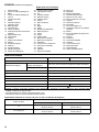
Symbols
The following show the symbols used for the equipment. Be sure that you understand their meaning before use.
Symboles
Nous donnons ci-dessous les symboles utilisés pour l’outil. Assurez-vous que vous en avez bien compris la
signification avant d’utiliser l’outil.
Symbole
Die folgenden Symbole werden für die Maschine verwendet. Machen Sie sich vor der Benutzung unbedingt mit ihrer
Bedeutung vertraut.
Simboli
Per questo utensile vengono usati i simboli seguenti. Bisogna capire il loro significato prima di usare l’utensile.
Symbolen
Voor dit gereedschap worden de volgende symbolen gebruikt. Zorg ervoor dat u de betekenis van deze symbolen
begrijpt alvorens het gereedschap te gebruiken.
Símbolos
A continuación se muestran los símbolos utilizados con esta herramienta. Asegúrese de que entiende su significado
antes de usarla.
Símbolos
O seguinte mostra os símbolos utilizados para a ferramenta. Certifique-se de que compreende o seu significado antes
da utilização.
Symboler
Nedenstående symboler er anvendt i forbindelse med denne maskine. Vær sikker på, at De har forstået symbolernes
betydning, før maskinen anvendes.
Σύμβολα
Τα ακόλουθα δείχνουν τα σύμβολα που χρησιμοποιούνται για το μηχάνημα. Βεβαιωθείτε ότι καταλαβαίνετε τη σημασία
τους πριν από τη χρήση.
Semboller
Aşağıdakiler makinanız için kullanılan sembolleri göstermektedir. Kullanmadan önce manalarını anladığınızdan emin
olunuz.
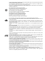
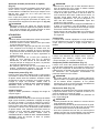
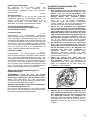
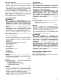
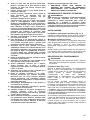
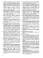
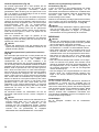
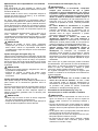
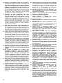
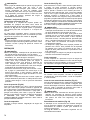
• Read instruction manual. • Lea el manual de instrucciones.
• Lire le mode d’emploi. • Leia o manual de instruções.
• Bitte Bedienungsanleitung lesen. • Læs brugsanvisningen.
• Leggete il manuale di istruzioni. • ∆ιαβάστε τις οδηγίες χρήσης.
• Lees de gebruiksaanwijzing. • El kitabını okuyun.
• DOUBLE INSULATION • DOBLE AISLAMIENTO
• DOUBLE ISOLATION • DUPLO ISOLAMENTO
• DOPPELT SCHUTZISOLIERT • DOBBELT ISOLERET
• DOPPIO ISOLAMENTO • ∆ΙΠΛΗ ΜΟΝΩΣΗ
• DUBBELE ISOLATIE • ÇİFT YALITIMLI
• Wear safety glasses. • Póngase gafas de seguridad.
• Portez des lunettes de sécurité. • Use óculos de segurança.
• Schutzbrille tragen. • Bær sikkerhedsbriller.
• Indossare occhiali di sicurezza. • Φοράτε γυαλιά ασφαλείας.
• Draag een veiligheidsbril. • Güvenlik gözlüğü takın.
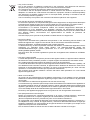
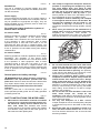
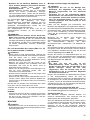
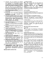
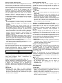
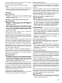
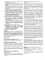
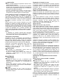
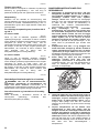
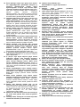
• To avoid injury from flying debris, keep holding the saw head down, after making cuts, until the blade
has come to a complete stop.
• Pour éviter les blessures causées par les objets projetés, maintenez la tête de la scie en position
basse une fois la coupe terminée, jusqu’à ce que la lame soit complètement arrêtée.
• Um Verletzungen durch herausgeschleuderte Teile zu vermeiden, halten Sie den Sägekopf nach
Ausführung von Schnitten abgesenkt, bis das Sägeblatt völlig zum Stillstand gekommen ist.
• Per evitare lesioni dalle schegge volanti, dopo aver eseguito il taglio tenere abbassata la testa sega
finché la lama non si è arrestata completamente.
• Om verwonding door weggeslingerd zaagafval te voorkomen, dient u na het voltooien van een snede
de zaagkop omlaag te houden totdat het zaagblad volledig tot stilstand is gekomen.
• Para evitar sufrir heridas a causa de restos que salen despedidos, siga sujetando la cabeza de la
sierra hacia abajo, al terminar los cortes, hasta que el disco se haya parado completamente.
• Para evitar danos causados por aparas que saltem, mantenha a cabeça da serra para baixo, depois
de terminar os cortes, até que a lâmina esteja completamente parada.

9
• For at undgå at komme til skade på grund af flyvende affald, skal man holde savhovedet nede efter
skæring, indtil savklingen står helt stille.
•Για να αποφύγετε τραυματισμό από ιπτάμενα τεμαχίδια, κρατάτε το πριόνι με το κεφάλι προς τα
κάτω, αφού κάνετε κοπές, μέχρι η λάμα να σταματήσει τελείως.
•Fırlayan toz ve talaşlardan kaçınmak için, kesme yaptıktan sonra, bıçak tamamen duruncaya kadar,
testereyi baş aşağı tutun.
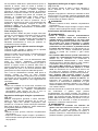
• Do not place hand or fingers close to the blade.
• Ne pas placer les mains ou les doigts près de la lame.
• Halten Sie Hände oder Finger vom Sägeblatt fern.
• Non avvicinare le mani o le dita alla lama.
• Kom met uw handen of vingers niet te dicht bij het zaagblad.
• No ponga la mano ni los dedos cerca del disco.
• Não coloque a sua mão ou dedos perto da lâmina.
• Hold hænder og fingre på god afstand af klingen.
•Μη βάζετε το χέρι ή τα δάκτυλα κοντά στην λάμα.
• Elinizi veya parmaklarınızı bıçağın yakınına koymayın.
• For your safety, remove the chips, small pieces, etc. from the table top before operation.
• Pour votre sécurité, retirez les copeaux et autres petites pièces présentes sur la table avant de
commencer le travail.
• Zur Sicherheit sollte die Tischplatte vor dem Betrieb von Spänen, Kleinteilen usw. gesäubert werden.
• Per la propria sicurezza, togliere i trucioli, frammenti, ecc., dalla superficie superiore del piano di
taglio prima di procedere.
• Verwijder voor uw eigen veiligheid zaagafval, stukjes hout e.d. van de werktafel alvorens te gaan
zagen.
• Por su propia seguridad, retire las virutas, trozos pequeños, etc., de encima de la mesa de trabajo
antes de iniciar la tarea.
• Para sua segurança, retire aparas, peças pequenas, etc., de cima da bancada antes da operação.
• Af sikkerhedsårsager skal spåner, små stykker etc. fjernes fra bordtoppen inden anvendelsen.
•Για την ασφάλειά σας, αφαιρέστε τα αποκοπίδια, μικρά κομμάτια, κλπ. από το τραπέζι πριν από την
λειτουργία.
• Güvenliğiniz için, çalışmaya başlamadan önce, tezgah üstündeki talaşları, küçük parçacıkları, vs.
temizleyin.
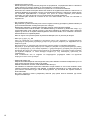
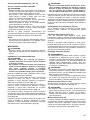
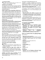
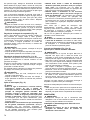
• Always set SUB-FENCE to left position when performing left bevel cuts. Failure to do so may cause
serious injury to operator.
• Lorsque vous effectuez des coupes en biseau sur la gauche, placez toujours la BUTÉE PARE-
ÉCLATS ROTATIVE à gauche. Sinon, il y a risque de blessure grave.
• Stellen Sie den ZUSATZANSCHLAG bei der Durchführung von Neigungsschnitten immer auf die
linke Position. Anderenfalls kann die Bedienungsperson ernsthaft verletzt werden.
• Posizionare sempre la guida pezzo secondaria a sinistra prima di eseguire i tagli a unghia. In caso
contrario, c’è pericolo di lesioni serie all’operatore.
• Zet de HULPGELEIDER altijd in de linkse positie wanneer u linkse schuine sneden wilt zagen. Als u
dit niet doet, kan de gebruiker ernstige verwonding oplopen.
• Ponga siempre la GUÍA AUXILIAR en la posición izquierda cuando realice cortes en bisel izquierdo.
De lo contrario, podrá sufrir graves heridas.
• Coloque sempre a GUIA AUXILIAR no lado esquerdo quando executa cortes de bisel à esquerda. Se
não o fizer pode ferir o operador.
• Anbing altid hjælpeanslaget (SUB-FENCE) i venstre position, når der laves skråsnit. Forsømmelse af
dette kan bevirke, at operatøren kommer alvorligt til skade.
•Πάντοτε ρυθμίζετε το SUB-FENCE (ΥΠΟ-ΦΡΑΚΤΗ) στην αριστερή θέση όταν εκτελείτε αριστερές
λοξές κοπές. Αμέλεια να το κάνετε μπορεί να προκαλέσει σοβαρό τραυματισμό στον χρήστη.
• Sola şevli kesme yaparken ALT KENARLIĞI daima sol konuma ayarlayın. Bunu yapmamak
kullanıcının ciddi şekilde yaralanmasına neden olabilir.

10
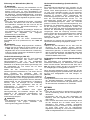
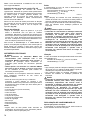
• To loosen the bolt, turn it clockwise.
• Pour desserrer le boulon, tournez-le vers la droite.
• Drehen Sie die Schraube zum Lösen im Uhrzeigersinn.
• Per allentare il bullone, girarlo in senso orario.
• Draai de bout rechtsom los.
• Para aflojar el perno, gírelo hacia la derecha.
• Para desapertar o perno, rode-o no sentido dos ponteiros do relógio.
• Bolten løsnes ved at den drejes i retningen med uret.
•Για να ξεσφίξετε τον κοχλία, περιστρέψτε δεξιόστροφα.
•Cıvatayı saat yönünde döndürerek gevşetin.

11
• Only for EU countries
Due to the presence of hazardous components in the equipment, used electrical and electronic
equipment may have a negative impact on the environment and human health.
Do not dispose of electrical and electronic appliances with household waste!
In accordance with the European Directive on waste electrical and electronic equipment and its
adaptation to national law, used electrical and electronic equipment should be collected separately
and delivered to a separate collection point for municipal waste, operating in accordance with the
environmental protection regulations.
This is indicated by the symbol of the crossed-out wheeled bin placed on the equipment.
• Pour les pays de l’Union européenne uniquement
En raison de la présence de composants dangereux dans l’équipement, les équipements électriques
et électroniques usagés peuvent avoir un impact négatif sur l’environnement et la santé humaine.
Ne jetez pas les appareils électriques et électroniques avec les ordures ménagères !
Conformément à la directive européenne relative aux déchets d’équipements électriques et
électroniques et à son adaptation à la législation nationale, les équipements électriques et
électroniques usagés doivent être collectés séparément et déposés dans un point de collecte distinct
pour déchets urbains, conformément aux réglementations en matière de protection de
l’environnement.
Cela est indiqué par le symbole de la poubelle à roulettes barrée sur l’équipement.
• Nur für EU-Länder
Aufgrund des Vorhandenseins gefährlicher Komponenten in der Ausrüstung können Elektro- und
Elektronik-Altgeräte sich negativ auf die Umwelt und die menschliche Gesundheit auswirken.
Entsorgen Sie Elektro- und Elektronikgeräte nicht mit dem Hausmüll!
In Übereinstimmung mit der Europäischen Richtlinie über Elektro- und Elektronik-Altgeräte und ihrer
Anpassung an nationales Recht sollten Elektro- und Elektronik-Altgeräte gemäß den
Umweltschutzbestimmungen getrennt gesammelt und zu einer getrennten Sammelstelle für
Siedlungsabfälle geliefert werden.
Dies wird durch das am Gerät angebrachte Symbol der durchgestrichenen Abfalltonne auf Rädern
angezeigt.
• Solo per le nazioni dell’EU
A causa della presenza di componenti pericolosi nelle apparecchiature, le apparecchiature elettriche
ed elettroniche usate potrebbero produrre un impatto negativo sull’ambiente e sulla salute umana.
Non smaltire elettrodomestici elettrici ed elettronici insieme ai rifiuti domestici!
In conformità alla direttiva europea sui rifiuti di apparecchiature elettriche ed elettroniche (RAEE), e al
suo adattamento alle normative nazionali, le apparecchiature elettriche ed elettroniche usate vanno
sottoposte a raccolta differenziata e conferite a un punto di raccolta separato per i rifiuti comunali,
operando in conformità alle normative per la protezione dell’ambiente.
Tale requisito viene indicato mediante il simbolo del bidone della spazzatura con ruote barrato
apposto sull’apparecchio.
• Alleen voor EU-landen
Als gevolg van de aanwezigheid van schadelijke componenten in het apparaat, kunnen gebruikte
elektrische en elektronische apparaten negatieve gevolgen hebben voor het milieu en de gezondheid
van mensen.
Gooi elektrische en elektronische apparaten niet met het huisvuil weg!
In overeenstemming met de Europese richtlijn inzake oude elektrische en elektronische apparaten en
de toepassing daarvan binnen de nationale wetgeving, dienen gebruikte elektrische en elektronische
apparaten gescheiden te worden ingezameld en te worden ingeleverd bij een apart inzamelingspunt
voor huishoudelijk afval dat de milieubeschermingsvoorschriften in acht neemt.
Dit wordt op het apparaat aangegeven door het symbool van een doorgekruiste afvalcontainer.
• Sólo para países de la Unión Europea
Debido a la presencia de componentes peligrosos en el equipo, el equipo eléctrico y electrónico
desechado puede tener un impacto negativo para el medioambiente y la salud humana.
¡No tire los aparatos eléctricos y electrónicos junto con los residuos domésticos!
De conformidad con las Directivas Europeas sobre residuos de aparatos eléctricos y electrónicos, y
su adaptación a la ley nacional, el equipo eléctrico y electrónico desechado deberá ser recogido por
separado y trasladado a un punto distinto de recogida de desechos municipales, que cumpla con los
reglamentos de protección medioambiental.
Esto se indica mediante el símbolo de cubo de basura tachado colocado en el equipo.

12
• Apenas para países da UE
Devido à presença de componentes perigosos no equipamento, o equipamento elétrico e eletrónico
usado pode ter um impacto negativo no meio ambiente e na saúde humana.
Não elimine aparelhos elétricos e eletrónicos juntamente com resíduos domésticos!
De acordo com a Diretiva europeia relativa aos resíduos de equipamentos elétricos e eletrónicos e a
respetiva adaptação à legislação nacional, os equipamentos elétricos e eletrónicos usados devem
ser recolhidos separadamente e entregues num ponto de recolha separado para resíduos
municipais, que opere de acordo com os regulamentos de proteção ambiental.
Tal é indicado pelo símbolo de contentor de lixo com rodas barrado com uma cruz colocado no
equipamento.
• Kun for lande inden for EU
Brugt elektrisk og elektronisk udstyr kan have en negativ indvirkning på miljøet og folkesundheden på
grund af tilstedeværelsen af farlige komponenter i udstyret.
Bortskaf ikke elektriske og elektroniske apparater sammen med husholdningsaffald!
I overensstemmelse med EF-direktiv om affaldshåndtering af elektrisk og elektronisk udstyr, og i
overensstemmelse med national lovgivning, skal brugt elektrisk og elektronisk udstyr opbevares
separat og leveres til et separat indsamlingssted til kommunalt affald, der er etableret i henhold til
bestemmelserne om miljøbeskyttelse.
Dette er angivet ved symbolet på den krydsede skraldespand, der er placeret på udstyret.
•Μόνο για τις χώρες της ΕΕ
Λόγω της παρουσίας των επικίνδυνων συστατικών μερών στον εξοπλισμό, ο χρησιμοποιημένος
ηλεκτρικός και ηλεκτρονικός εξοπλισμός μπορεί να έχει αρνητική επίδραση στο περιβάλλον και την
ανθρώπινη υγεία.
Μην απορρίπτετε τις ηλεκτρικές και ηλεκτρονικές συσκευές μαζί με τα οικιακά απορρίμματα!
Σύμφωνα με την Ευρωπαϊκή Οδηγία για τον απόβλητο ηλεκτρικό και ηλεκτρονικό εξοπλισμό, καθώς
και την προσαρμογή της στην εθνική νομοθεσία, ο χρησιμοποιημένος ηλεκτρικός και ηλεκτρονικός
εξοπλισμός θα πρέπει να συλλέγεται ξεχωριστά και να παραδίδεται σε ξεχωριστό σημείο συλλογής
για δημοτικά απόβλητα, το οποίο λειτουργεί σύμφωνα με τους κανονισμούς προστασίας του
περιβάλλοντος.
Αυτό υποδεικνύεται από το σύμβολο του διαγραμμένου τροχοφόρου κάδου που βρίσκεται
αναρτημένο επάνω στον εξοπλισμό.
• Sadece AB ülkeleri için
Ekipmanda tehlikeli bileşenler bulunduğundan dolayı eski elektrikli ve elektronik ekipmanlar çevre ve
insan sağlığı üzerinde olumsuz etkiye yol açabilir.
Elektrikli ve elektronik cihazları evsel atıklarla birlikte atmayın!
Atık elektrikli ve elektronik ekipmanlar hakkındaki Avrupa Direktifi ve söz konusu direktifin ulusal
yasalara uyarlanması gereğince eski elektrikli ve elektronik ekipmanlar ayrı olarak toplanmalı ve
çevre koruma mevzuatına uygun olarak faaliyet gösteren ayrı bir kentsel atık toplama noktasına
teslim edilmelidir.
Bu husus, ekipmanın üzerine yerleştirilmiş üzerinde çarpı işareti bulunan tekerlekli çöp kovası
simgesi ile belirtilmiştir.

13
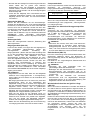
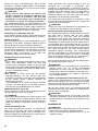
ENGLISH (Original instructions)
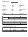
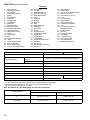
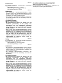
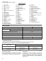
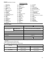
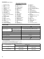
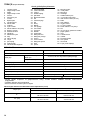
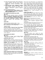
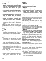
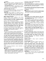
Explanation of general view
1 Auxiliary plate
2Hex bolt
3Base
4Hex bolt
5Nut
6 Stopper pin
7Bolt
8 Blade guard
9 Kerf board
10 Turn base
11 Socket wrench
12 Adjusting bolt
13 Top surface of turn base
14 Periphery of blade
15 Guide fence
16 Pointer
17 Lock lever
18 Grip
19 Miter scale
20 Lever
21 Bevel scale
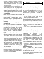
22 Switch trigger
23 Lock-off button
24 Hole for padlock
25 Light switch
26 Light
27 Center cover
28 Shaft lock
29 Blade case
30 Arrow
31 Saw blade
32 Spindle
33 Flange
34 Ring
35 Dust nozzle
36 Dust bag
37 Fastener
38 Support
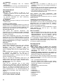
39 Sub-fence
40 Vise arm
41 Vise rod
42 Holder
43 Holder assembly
44 Vise knob
45 Screw
46 Projection
47 Vise shaft
48 Rod 12
49 Vise
50 Spacer block
51 Aluminum extrusion
52 Over 10 mm (3/8”)
53 Over 460 mm (18-1/8”)
54 Hole
55 Set plate
56 Triangular rule
57 0° adjusting bolt
58 Top surface of turn base
59 Arm
60 45° bevel angle adjusting bolt
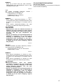
61 Pull out
62 Push
63 Lamp box
64 Screws
65 Fluorescent tube
66 Limit mark
67 Screwdriver
68 Brush holder cap
SPECIFICATIONS
• Due to our continuing program of research and development, the specifications herein are subject to change without
notice.
• Specifications may differ from country to country.
• Weight according to EPTA-Procedure 01/2014
Max. cutting capacities (H x W) with blade 260 mm in diameter
Model LS1040 / LS1040S LS1040F / LS1040FS
Blade diameter 255 mm - 260 mm
Hole diameter
For all countries other than
European countries 25.4 mm, 25 mm or 30 mm (Country specific)
For European countries 30 mm
Max. kerf thickness of the saw blade 3.2 mm
Max. Miter angle Left 45°, Right 52°
Max. Bevel angle Left 45°
No load speed 5,100 min-1
Dimensions (L x W x H) 530 mm x 476 mm x 532 mm
Net weight 11.8 kg 12.0 kg
Safety class /II
Bevel angle Miter angle
0° 45° (left and right)
0° 93 mm x 95 mm
69 mm x 135 mm
93 mm x 67 mm
69 mm x 95 mm
45° (left) 53 mm x 95 mm
35 mm x 135 mm
49 mm x 67 mm
35 mm x 94 mm

14
ENE004-1
Intended use
The tool is intended for accurate straight and miter
cutting in wood. With appropriate saw blades, aluminum
can also be sawed.
ENF002-2
Power supply
The tool should be connected only to a power supply of
the same voltage as indicated on the nameplate, and can
only be operated on single-phase AC supply. They are
double-insulated and can, therefore, also be used from
sockets without earth wire.
For public low-voltage distribution systems of
between 220 V and 250 V
For model LS1040
ENF100-1
Switching operations of electric apparatus cause voltage
fluctuations. The operation of this device under
unfavorable mains conditions can have adverse effects
to the operation of other equipment. With a mains
impedance equal or less than 0.29 Ohms it can be
presumed that there will be no negative effects. The
mains socket used for this device must be protected with
a fuse or protective circuit breaker having slow tripping
characteristics.
For model LS1040F
ENF100-1
Switching operations of electric apparatus cause voltage
fluctuations. The operation of this device under
unfavorable mains conditions can have adverse effects
to the operation of other equipment. With a mains
impedance equal or less than 0.34 Ohms it can be
presumed that there will be no negative effects. The
mains socket used for this device must be protected with
a fuse or protective circuit breaker having slow tripping
characteristics.
GEA010-2
General power tool safety warnings
WARNING Read all safety warnings, instructions,
illustrations and specifications provided with this
power tool. Failure to follow all instructions listed below
may result in electric shock, fire and/or serious injury.
Save all warnings and instructions for future
reference.
The term “power tool” in the warnings refers to your
mains-operated (corded) power tool or battery-operated
(cordless) power tool.
ENB131-1
SAFETY INSTRUCTIONS FOR MITRE SAWS
1. Mitre saws are intended to cut wood or woodlike
products, they cannot be used with abrasive cut-
off wheels for cutting ferrous material such as
bars, rods, studs, etc. Abrasive dust causes
moving parts such as the lower guard to jam. Sparks
from abrasive cutting will burn the lower guard, the
kerf insert and other plastic parts.
2. Use clamps to support the workpiece whenever
possible. If supporting the workpiece by hand,
you must always keep your hand at least
100 mm from either side of the saw blade. Do not
use this saw to cut pieces that are too small to
be securely clamped or held by hand. If your
hand is placed too close to the saw blade, there is
an increased risk of injury from blade contact.
3. The workpiece must be stationary and clamped
or held against both the fence and the table. Do
not feed the workpiece into the blade or cut
“freehand” in any way. Unrestrained or moving
workpieces could be thrown at high speeds, causing
injury.
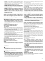
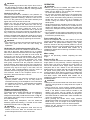
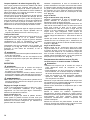
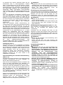
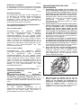
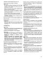
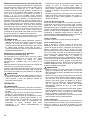
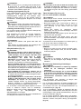
4. Never cross your hand over the intended line of
cutting either in front or behind the saw blade.
Supporting the workpiece “cross handed” i.e.
holding the workpiece to the right of the saw blade
with your left hand or vice versa is very dangerous.
000030
5. Do not reach behind the fence with either hand
closer than 100 mm from either side of the saw
blade, to remove wood scraps, or for any other
reason while the blade is spinning. The proximity
of the spinning saw blade to your hand may not be
obvious and you may be seriously injured.
6. Inspect your workpiece before cutting. If the
workpiece is bowed or warped, clamp it with the
outside bowed face toward the fence. Always
make certain that there is no gap between the
workpiece, fence and table along the line of the
cut. Bent or warped workpieces can twist or shift
and may cause binding on the spinning saw blade
while cutting. There should be no nails or foreign
objects in the workpiece.
7. Do not use the saw until the table is clear of all
tools, wood scraps, etc., except for the
workpiece. Small debris or loose pieces of wood or
other objects that contact the revolving blade can be
thrown with high speed.
8. Cut only one workpiece at a time. Stacked
multiple workpieces cannot be adequately clamped
or braced and may bind on the blade or shift during
cutting.
9. Ensure the mitre saw is mounted or placed on a
level, firm work surface before use. A level and
firm work surface reduces the risk of the mitre saw
becoming unstable.

15
10. Plan your work. Every time you change the bevel
or mitre angle setting, make sure the adjustable
fence is set correctly to support the workpiece
and will not interfere with the blade or the
guarding system. Without turning the tool “ON” and
with no workpiece on the table, move the saw blade
through a complete simulated cut to assure there
will be no interference or danger of cutting the fence.
11. Provide adequate support such as table
extensions, saw horses, etc. for a workpiece that
is wider or longer than the table top. Workpieces
longer or wider than the mitre saw table can tip if not
securely supported. If the cut-off piece or workpiece
tips, it can lift the lower guard or be thrown by the
spinning blade.
12. Do not use another person as a substitute for a
table extension or as additional support.
Unstable support for the workpiece can cause the
blade to bind or the workpiece to shift during the
cutting operation pulling you and the helper into the
spinning blade.
13. The cut-off piece must not be jammed or
pressed by any means against the spinning saw
blade. If confined, i.e. using length stops, the cut-off
piece could get wedged against the blade and
thrown violently.
14. Always use a clamp or a fixture designed to
properly support round material such as rods or
tubing. Rods have a tendency to roll while being
cut, causing the blade to “bite” and pull the work with
your hand into the blade.
15. Let the blade reach full speed before contacting
the workpiece. This will reduce the risk of the
workpiece being thrown.
16. If the workpiece or blade becomes jammed, turn
the mitre saw off. Wait for all moving parts to
stop and disconnect the plug from the power
source and/or remove the battery pack. Then
work to free the jammed material. Continued
sawing with a jammed workpiece could cause loss
of control or damage to the mitre saw.
17. After finishing the cut, release the switch, hold
the saw head down and wait for the blade to stop
before removing the cut-off piece. Reaching with
your hand near the coasting blade is dangerous.
18. Hold the handle firmly when making an
incomplete cut or when releasing the switch
before the saw head is completely in the down
position. The braking action of the saw may cause
the saw head to be suddenly pulled downward,
causing a risk of injury.
19. Only use the saw blade with the diameter that is
marked on the tool or specified in the manual.
Use of an incorrectly sized blade may affect the
proper guarding of the blade or guard operation
which could result in serious personal injury.
20. Only use the saw blades that are marked with a
speed equal or higher than the speed marked on
the tool.
21. Do not use the saw to cut other than wood,
aluminum or similar materials.
22. (For European countries only)
Always use the blade which conforms to EN847-
1.
Additional instructions
1. Make workshop kid proof with padlocks.
2. Never stand on the tool. Serious injury could occur
if the tool is tipped or if the cutting tool is
unintentionally contacted.
3. Never leave the tool running unattended. Turn
the power off. Do not leave tool until it comes to
a complete stop.
4. Do not operate saw without guards in place.
Check blade guard for proper closing before each
use. Do not operate saw if blade guard does not
move freely and close instantly. Never clamp or
tie the blade guard into the open position.
5. Keep hands out of path of saw blade. Avoid
contact with any coasting blade. It can still
cause severe injury.
6. Always secure all moving portions before
carrying the tool.
7. Stopper pin which locks the cutter head down is
for carrying and storage purposes only and not
for any cutting operations.
8. Check the blade carefully for cracks or damage
before operation. Replace cracked or damaged
blade immediately. Gum and wood pitch
hardened on blades slows saw and increases
potential for kickback. Keep blade clean by first
removing it from tool, then cleaning it with gum
and pitch remover, hot water or kerosene. Never
use gasoline to clean blade.
9. Use only flanges specified for this tool.
10. Be careful not to damage the arbor, flanges
(especially the installing surface) or bolt.
Damage to these parts could result in blade
breakage.
11. Make sure that the turn base is properly secured
so it will not move during operation. Use the
holes in the base to fasten the saw to a stable
work platform or bench. NEVER use tool where
operator positioning would be awkward.
12. Make sure the shaft lock is released before the
switch is turned on.
13. Be sure that the blade does not contact the turn
base in the lowest position.
14. Hold the handle firmly. Be aware that the saw
moves up or down slightly during start-up and
stopping.
15. Make sure the blade is not contacting the
workpiece before the switch is turned on.
16. Before using the tool on an actual workpiece, let
it run for a while. Watch for vibration or wobbling
that could indicate poor installation or a poorly
balanced blade.
17. Stop operation immediately if you notice
anything abnormal.
18. Do not attempt to lock the trigger in the “ON”
position.
19. Always use accessories recommended in this
manual. Use of improper accessories such as
abrasive wheels may cause an injury.
20. Some material contains chemicals which may be
toxic. Take caution to prevent dust inhalation
and skin contact. Follow material supplier safety
data.
Additional safety rules for the laser
1. LASER RADIATION, DO NOT STARE INTO THE
BEAM OR VIEW DIRECTLY WITH OPTICAL
INSTRUMENTS, CLASS 2M LASER PRODUCT.
SAVE THESE INSTRUCTIONS.

16
WARNING:
DO NOT let comfort or familiarity with product
(gained from repeated use) replace strict adherence
to safety rules for the subject product. MISUSE or
failure to follow the safety rules stated in this
instruction manual may cause serious personal
injury.
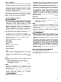
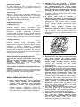
INSTALLATION
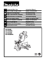
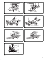
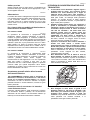
Installing auxiliary plate (Fig. 1 & 2)
Install the auxiliary plate using the notch in the tool’s
base and secure it by tightening the hex bolt.
Bench mounting
When the tool is shipped, the handle is locked in the
lowered position by the stopper pin. Release the stopper
pin by lowering the handle slightly and pulling the stopper
pin. (Fig. 3)
This tool should be bolted with two bolts to a level and
stable surface using the bolt holes provided in the tool’s
base. This will help prevent tipping and possible personal
injury. (Fig. 4)
FUNCTIONAL DESCRIPTION
CAUTION:
• Always be sure that the tool is switched off and
unplugged before adjusting or checking function on the
tool.
Blade guard (Fig. 5 & 6)
When lowering the handle, the blade guard rises
automatically. The guard is spring loaded so it returns to
its original position when the cut is completed and the
handle is raised. NEVER DEFEAT OR REMOVE THE
BLADE GUARD OR THE SPRING WHICH ATTACHES
TO THE GUARD.
In the interest of your personal safety, always maintain
the blade guard in good condition. Any irregular
operation of the blade guard should be corrected
immediately. Check to assure spring loaded return action
of guard. NEVER USE THE TOOL IF THE BLADE
GUARD OR SPRING ARE DAMAGED, FAULTY OR
REMOVED. DOING SO IS HIGHLY DANGEROUS AND
CAN CAUSE SERIOUS PERSONAL INJURY.
If the see-through blade guard becomes dirty, or sawdust
adheres to it in such a way that the blade is no longer
easily visible, unplug the saw and clean the guard
carefully with a damp cloth. Do not use solvents or any
petroleum-based cleaners on the plastic guard.
If the blade guard is especially dirty and vision through
the guard is impaired, use the supplied socket wrench to
loosen the hex bolt holding the center cover. Loosen the
hex bolt by turning it counterclockwise and raise the
blade guard and center cover. With the blade guard so
positioned, cleaning can be more completely and
efficiently accomplished. When cleaning is complete,
reverse procedure above and secure bolt. Do not remove
spring holding blade guard. If guard becomes discolored
through age or UV light exposure, contact a Makita
service center for a new guard. DO NOT DEFEAT OR
REMOVE GUARD.
Kerf board (Fig. 7)
This tool is provided with the kerf board in the turn base
to minimize tearing on the exit side of a cut. If the kerf
groove has not yet been cut in the kerf board by the
factory, you should cut the groove before actually using
the tool to cut a workpiece. Switch on the tool and lower
the blade gently to cut a groove in the kerf board.
Maintaining maximum cutting capacity
(Fig. 8 & 9)
This tool is factory adjusted to provide the maximum
cutting capacity for a 260 mm saw blade.
When installing a new blade, always check the lower limit
position of the blade and if necessary, adjust it as follows:
First, unplug the tool. Lower the handle completely. Use
the socket wrench to turn the adjusting bolt until the
periphery of the blade extends slightly below the top
surface of the turn base at the point where the front face
of the guide fence meets the top surface of the turn base.
With the tool unplugged, rotate the blade by hand while
holding the handle all the way down to be sure that the
blade does not contact any part of the lower base. Re-
adjust slightly, if necessary.
CAUTION:
• After installing a new blade, always be sure that the
blade does not contact any part of the lower base when
the handle is lowered completely. Always do this with
the tool unplugged.
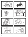
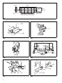
Adjusting the miter angle (Fig. 10)
Loosen the grip by turning counterclockwise. Turn the
turn base while pressing down the lock lever. When you
have moved the grip to the position where the pointer
points to the desired angle on the miter scale, securely
tighten the grip clockwise.
CAUTION:
• When turning the turn base, be sure to raise the handle
fully.
• After changing the miter angle, always secure the turn
base by tightening the grip firmly.
Adjusting the bevel angle (Fig. 11 & 12)
To adjust the bevel angle, loosen the lever at the rear of
the tool counterclockwise.
Push the handle to the left to tilt the saw blade until the
pointer points to the desired angle on the bevel scale.
Then tighten the lever clockwise firmly to secure the arm.
CAUTION:
• When tilting the saw blade, be sure to raise the handle
fully.
• After changing the bevel angle, always secure the arm
by tightening the lever clockwise.
Switch action (Fig. 13)
WARNING:
•Before plugging in the tool, always check to see
that the switch trigger actuates properly and
returns to the “OFF” position when released. Do
not pull the switch trigger hard without pressing in
the lock-off button. This can cause switch
breakage. Operating a tool with a switch that does not
actuate properly can lead to loss of control and serious
personal injury.

17
•NEVER use tool without a fully operative switch
trigger. Any tool with an inoperative switch is HIGHLY
DANGEROUS and must be repaired before further
usage or serious personal injury may occur.
•NEVER defeat the lock-off button by taping down
or some other means. A switch with a negated lock-
off button may result in unintentional operation and
serious personal injury.
•NEVER use the tool if it runs when you simply pull
the switch trigger without pressing the lock-off
button. A switch in need of repair may result in
unintentional operation and serious personal injury.
Return tool to a Makita service center for proper repairs
BEFORE further usage.
To prevent the switch trigger from being accidentally
pulled, a lock-off button is provided. To start the tool,
press in the lock-off button and pull the switch trigger.
Release the switch trigger to stop.
A hole is provided in the switch trigger for insertion of a
padlock to lock the tool off.
WARNING:
•Do not use a lock with a shank or cable any smaller
than 6.35 mm in diameter. A smaller shank or cable
may not properly lock the tool in the off position and
unintentional operation may occur resulting in serious
personal injury.
Lighting up the lamps (Fig. 14 & 15)
Only for model LS1040F / LS1040FS
CAUTION:
• This is not a rainproof light. Do not wash the light in
water or use it in a rain or a wet area. Such a conduct
can cause an electric shock and fume.
• Do not touch the lens of the light, as it is very hot while
it is lighted or shortly after it is turned off. This may
cause a burn to a human body.
• Do not apply impact to the light, which may cause
damage or shorted service time to it.
• Do not keep casting the beam of the light to your eyes.
This can cause your eyes to be hurt.
• Do not cover the light with clothes, carton, cardboard or
similar objects while it is lighted, which can cause a fire
or an ignition.
Push the upper position of the switch for turning on the
light and the lower position for off.
Move the light to shift an area of lighting.
NOTE:
• Use a dry cloth to wipe the dirt off the lens of lamp. Be
careful not to scratch the lens of light, or it may lower
the illumination.
ASSEMBLY
CAUTION:
• Always be sure that the tool is switched off and
unplugged before carrying out any work on the tool.
Installing or removing saw blade
CAUTION:
• Always be sure that the tool is switched off and
unplugged before installing or removing the blade.
• Use only the Makita socket wrench provided to
install or remove the blade. Failure to do so may
result in overtightening or insufficient tightening of
the hex bolt. This could cause an injury.
When removing or installing the blade, keep the handle
in the raised position.
To remove the blade, use the socket wrench to loosen
the hex bolt holding the center cover by turning it
counterclockwise. Raise the blade guard and center
cover. (Fig. 16)
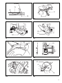
Press the shaft lock to lock the spindle and use the
socket wrench to loosen the hex bolt clockwise. Then
remove the hex bolt, outer flange and blade. (Fig. 17)
To install the blade, mount it carefully onto the spindle,
making sure that the direction of the arrow on the surface
of the blade matches the direction of the arrow on the
blade case. (Fig. 18)
Install the flange and hex bolt, and then use the socket
wrench to tighten the hex bolt (left-handed) securely
counterclockwise while pressing the shaft lock. (Fig. 19)
CAUTION:
• The ring 25.4 mm or 30 mm in outer diameter is
factory-installed onto the spindle. Before mounting
the blade onto the spindle, always be sure that the
correct ring for the arbor hole of the blade you
intend to use is installed onto the spindle.
Return the blade guard and center cover to its original
position. Then tighten the hex bolt clockwise to secure
the center cover. Lower the handle to make sure that the
blade guard moves properly. Make sure shaft lock has
released spindle before making cut.
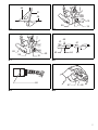
Connecting a vacuum cleaner (Fig. 20)
When you wish to perform clean cutting operation,
connect a Makita vacuum cleaner.
Dust bag (Fig. 21)
The use of the dust bag makes cutting operations clean
and dust collection easy. To attach the dust bag, fit it onto
the dust nozzle.
When the dust bag is about half full, remove the dust bag
from the tool and pull the fastener out. Empty the dust
bag of its contents, tapping it lightly so as to remove
particles adhering to the insides which might hamper
further collection.
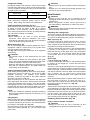
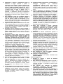
Securing workpiece (Fig. 22)
WARNING:
• It is extremely important to always secure the
workpiece properly and tightly with the vise. Failure to
do so can cause the tool to be damaged and/or the
workpiece to be destroyed. PERSONAL INJURY MAY
ALSO RESULT. Also, after a cutting operation, DO
NOT raise the blade until the blade has come to a
complete stop.
CAUTION:
• When cutting long workpieces, use supports that are as
high as the top surface level of the turn base. Do not
rely solely on the vertical vise and/ or horizontal vise to
secure the workpiece.
Thin material tends to sag. Support workpiece over its
entire length to avoid blade pinch and possible
KICKBACK.
Sub-fence (Fig. 23 & 24)
This tool is equipped with the sub-fence. It should be
positioned as shown in Fig. 23.

18
CAUTION:
• When performing left bevel cuts, flip the fence over to
the left position as shown in Fig. 24. Otherwise, it will
contact the blade or a part of the tool, causing possible
serious injury to the operator.
Vertical vise (Fig. 25)
The vertical vise can be installed in two positions on
either the left or right side of the guide fence or the holder
assembly (optional accessory). Insert the vise rod into
the hole in the guide fence or the holder assembly and
tighten the screw to secure the vise rod.
Position the vise arm according to the thickness and
shape of the workpiece and secure the vise arm by
tightening the screw. If the screw to secure the vise arm
contacts the guide fence, install the screw on the
opposite side of vise arm. Make sure that no part of the
tool contacts the vise when lowering the handle all the
way. If some part contacts the vise, re-position the vise.
Press the workpiece flat against the guide fence and the
turn base. Position the workpiece at the desired cutting
position and secure it firmly by tightening the vise knob.
CAUTION:
• The workpiece must be secured firmly against the turn
base and guide fence with the vise during all
operations.
Horizontal vise (optional accessory) (Fig. 26)
The horizontal vise can be installed on either the left or
right side of the base. When performing 15° or greater
miter cuts, install the horizontal vise on the side opposite
the direction in which the turn base is to be turned. By
turning the vise knob counterclockwise, the screw is
released and the vise shaft can be moved rapidly in and
out. By turning the vise knob clockwise, the screw
remains secured. To grip the workpiece, turn the vise
knob gently clockwise until the projection reaches its
topmost position, then fasten securely. If the vise knob is
forced in or pulled out while being turned clockwise, the
projection may stop at an angle. In this case, turn the
vise knob back counterclockwise until the screw is
released, before turning again gently clockwise.
The maximum width of the workpiece which can be
secured by the horizontal vise is 130 mm.
CAUTION:
• Grip the workpiece only when the projection is at the
topmost position. Failure to do so may result in
insufficient securing of the workpiece. This could cause
the workpiece to be thrown, cause damage to the blade
or cause the loss of control, which can result in
PERSONAL INJURY.
Holders and holder assembly
(optional accessories) (Fig. 27)
The holders and the holder assembly can be installed on
either side as a convenient means of supporting
workpieces horizontally. Install them as shown in Fig. 27.
Then tighten the screws firmly to secure the holders and
the holder assembly.
When cutting long workpieces, use the holder-rod
assembly (optional accessory). It consists of two holder
assemblies and two rods 12. (Fig. 28)
CAUTION:
• Always support long workpieces level with the top
surface of the turn base for accurate cuts and to
prevent dangerous loss of control of the tool.
OPERATION
CAUTION:
• Before use, be sure to release the handle from the
lowered position by pulling the stopper pin.
• Make sure the blade is not contacting the workpiece,
etc. before the switch is turned on.
• Do not apply excessive pressure on the handle when
cutting. Too much force may result in overload of the
motor and/or decreased cutting efficiency. Push down
handle with only as much force as is necessary for
smooth cutting and without significant decrease in
blade speed.
• Gently press down the handle to perform the cut. If the
handle is pressed down with force or if lateral force is
applied, the blade will vibrate and leave a mark (saw
mark) in the workpiece and the precision of the cut will
be impaired.
• Do not release the saw head uncontrolled from the fully
down position. Uncontrolled saw head may hit you and
it will result in personal injury.
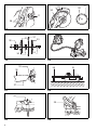
Press cutting (Fig. 29)
Secure the workpiece with the vise. Switch on the tool
without the blade making any contact and wait until the
blade attains full speed before lowering. Then gently
lower the handle to the fully lowered position to cut the
workpiece. When the cut is completed, switch off the tool
and WAIT UNTIL THE BLADE HAS COME TO A
COMPLETE STOP before returning the blade to its fully
elevated position.
Miter cutting
Refer to the previously covered “Adjusting the miter
angle”.
Bevel cut (Fig. 30)
Loosen the lever and tilt the saw blade to set the bevel
angle (Refer to the previously covered “Adjusting the
bevel angle”). Be sure to retighten the lever firmly to
secure the selected bevel angle safely. Secure the
workpiece with a vise. Switch on the tool without the
blade making any contact and wait until the blade attains
full speed. Then gently lower the handle to the fully
lowered position while applying pressure in parallel with
the blade. When the cut is completed, switch off the tool
and WAIT UNTIL THE BLADE HAS COME TO A
COMPLETE STOP before returning the blade to its fully
elevated position.
CAUTION:
• Always be sure that the blade will move down to bevel
direction during a bevel cut. Keep hands out of path of
saw blade.
• During a bevel cut, it may create a condition whereby
the piece cut off will come to rest against the side of the
blade. If the blade is raised while the blade is still
rotating, this piece may be caught by the blade,
causing fragments to be scattered which is dangerous.
The blade should be raised ONLY after the blade has
come to a complete stop.
• When pressing the handle down, apply pressure
parallel to the blade. If the pressure is not parallel to the
blade during a cut, the angle of the blade might be
shifted and the precision of the cut will be impaired.
• Always set the sub-fence to the left position when
performing left bevel cuts.

19
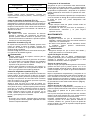
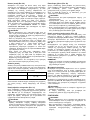
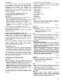
Compound cutting
Compound cutting is the process in which a bevel angle
is made at the same time in which a miter angle is being
cut on a workpiece. Compound cutting can be performed
at angle shown in the table.
006389
When performing compound cutting, refer to “Press
cutting”, “Miter cutting” and “Bevel cut” explanations.
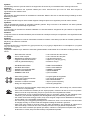
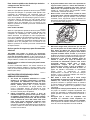
Cutting aluminum extrusion (Fig. 31)
When securing aluminum extrusions, use spacer blocks
or pieces of scrap as shown in Fig. 31 to prevent
deformation of the aluminum. Use a cutting lubricant
when cutting the aluminum extrusion to prevent build-up
of the aluminum material on the blade.
CAUTION:
• Never attempt to cut thick or round aluminum
extrusions. Thick aluminum extrusions may come
loose during operation and round aluminum extrusions
cannot be secured firmly with this tool.
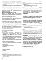
Wood facing (Fig. 32)
Use of wood facing helps to assure splinter-free cuts in
workpieces. Attach a wood facing to the guide fence
using the holes in the guide fence.
See Fig. 32 concerning the dimensions for a suggested
wood facing.
CAUTION:
• Use straight wood of even thickness as the wood
facing.
• Use screws to attach the wood facing to the guide
fence. The screws should be installed so that the screw
heads are below the surface of the wood facing.
• When the wood facing is attached, do not turn the turn
base with the handle lowered. The blade and/or the
wood facing will be damaged.
Cutting repetitive lengths (Fig. 33)
When cutting several pieces of stock to the same length,
ranging from 240 mm to 400 mm, use of the set plate
(optional accessory) will facilitate more efficient
operation. Install the set plate on the holder (optional
accessory) as shown in Fig. 33.
Align the cutting line on your workpiece with either the
left or right side of the groove in the kerf board, and while
holding the workpiece from moving, move the set plate
flush against the end of the workpiece. Then secure the
set plate with the screw. When the set plate is not used,
loosen the screw and turn the set plate out of the way.
NOTE:
• Use of the holder-rod assembly (optional accessory)
allows cutting repetitive lengths up to 2,200 mm (7.2 ft.)
approximately.
Carrying tool
Make sure that the tool is unplugged. Secure the blade at
0° bevel angle and the turn base at left miter angle fully.
Lower the handle fully and lock it in the lowered position
by pushing in the stopper pin. (Fig. 34)
Carry the tool by carrying grip as shown in Fig. 35. If you
remove the holders, dust bag, etc., you can carry the tool
more easily.
CAUTION:
• Always secure all moving portions before carrying the
tool.
• Stopper pin is for carrying and storage purposes only
and not for any cutting operations.
MAINTENANCE
CAUTION:
• Always be sure that the tool is switched off and
unplugged before attempting to perform inspection or
maintenance.
• Never use gasoline, benzine, thinner, alcohol or the
like. Discoloration, deformation or cracks may result.
WARNING:
• Always be sure that the blade is sharp and clean for the
best and safest performance.
Adjusting the cutting angle
This tool is carefully adjusted and aligned at the factory,
but rough handling may have affected the alignment. If
your tool is not aligned properly, perform the following:
Miter angle (Fig. 36)
Loosen the grip which secures the turn base. Turn the
turn base so that the pointer points to 0° on the miter
scale. Tighten the grip and loosen the hex bolts securing
the guide fence using the socket wrench.
Lower the handle fully and lock it in the lowered position
by pushing in the stopper pin. Square the side of the
blade with the face of the guide fence using a triangular
rule, try-square, etc. Then securely tighten the hex bolts
on the guide fence in the order from the right side.
(Fig. 37)
Bevel angle
0° bevel angle (Fig. 38 & 39)
Lower the handle fully and lock it in the lowered position
by pushing in the stopper pin. Loosen the lever at the
rear of the tool.
Turn the 0° bevel angle adjusting bolt on the right side of
the turn base two or three revolutions clockwise to tilt the
blade to the right. Carefully square the side of the blade
with the top surface of the turn base using the triangular
rule, try-square, etc. by turning the 0° bevel angle
adjusting bolt counterclockwise. Then tighten the lever
securely.
Make sure that the pointer on the turn base point to 0° on
the bevel scale on the arm. If it does not point to 0°,
loosen the screw which secures the pointer and adjust
the pointer so that it will point to 0°. (Fig. 40)
45° bevel angle
Adjust the 45° bevel angle only after performing 0° bevel
angle adjustment. To adjust left 45° bevel angle, loosen
the lever and tilt the blade to the left fully. Make sure that
the pointer on the arm points to 45° on the bevel scale on
the arm holder. If the pointer does not point to 45°, turn
the 45° bevel angle adjusting bolt on the left side of the
arm until the pointer points to 45°. (Fig. 41)
Replacing fluorescent tube (Fig. 42)
Only for model LS1040F / LS1040FS
CAUTION:
• Always be sure that the tool is switched off and
unplugged before replacing the fluorescent tube.
Bevel angle Miter angle
45° Left and Right 0° – 45°

20
• Do not apply force, impact or scratch to a fluorescent
tube, which can cause a glass of the fluorescent tube
to be broken resulting in a injury to you or your
bystanders.
• Leave the florescent tube for a while immediately after
a use of it and then replace it. If not, you may burn
yourself.
Remove screws, which secure Lamp box for the light.
Pull out the Lamp box keeping pushing lightly the upper
position of it as illustrated on Fig. 42.
Pull out the fluorescent tube and then replace it with
Makita original new one.
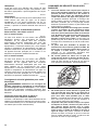
Replacing carbon brushes (Fig. 43)
Remove and check the carbon brushes regularly.
Replace when they wear down to the limit mark. Keep
the carbon brushes clean and free to slip in the holders.
Both carbon brushes should be replaced at the same
time. Use only identical carbon brushes.
Use a screwdriver to remove the brush holder caps. Take
out the worn carbon brushes, insert the new ones and
secure the brush holder caps. (Fig. 44)
After use
• After use, wipe off chips and dust adhering to the tool
with a cloth or the like. Keep the blade guard clean
according to the directions in the previously covered
section titled “Blade guard”. Lubricate the sliding
portions with machine oil to prevent rust.
To maintain product SAFETY and RELIABILITY, repairs,
any other maintenance or adjustment should be
performed by Makita Authorized Service Centers, always
using Makita replacement parts.
OPTIONAL ACCESSORIES
WARNING:
•These Makita accessories or attachments are
recommended for use with your Makita tool
specified in this manual. The use of any other
accessories or attachments may result in serious
personal injury.
•Only use the Makita accessory or attachment for its
stated purpose. Misuse of an accessory or attachment
may result in serious personal injury.
If you need any assistance for more details regarding
these accessories, ask your local Makita service center.
• Steel & Carbide-tipped saw blade
(Refer to our website or contact your local Makita
dealer for the correct saw blades to be used for the
material to be cut.)
• Auxiliary plate
• Vise assembly (Horizontal vise)
• Vertical vise
• Socket wrench
•Holder set
• Holder assembly
• Holder rod assembly
• Set plate
• Dust bag
• Triangular rule
• Fluorescent tube
NOTE:
• Some items in the list may be included in the tool
package as standard accessories. They may differ from
country to country.
ENG905-1
Noise
The typical A-weighted noise level determined according
to EN62841-3-9:
Sound pressure level (LpA): 91 dB (A)
Sound power level (LWA): 101 dB (A)
Uncertainty (K): 3 dB (A)
ENG907-1
NOTE:
• The declared noise emission value(s) has been
measured in accordance with a standard test method
and may be used for comparing one tool with another.
• The declared noise emission value(s) may also be
used in a preliminary assessment of exposure.
WARNING:
• Wear ear protection
• The noise emission during actual use of the power
tool can differ from the declared value(s)
depending on the ways in which the tool is used
especially what kind of workpiece is processed.
• Be sure to identify safety measures to protect the
operator that are based on an estimation of
exposure in the actual conditions of use (taking
account of all parts of the operating cycle such as
the times when the tool is switched off and when it
is running idle in addition to the trigger time).
ENG900-1
Vibration
The vibration total value (tri-axial vector sum) determined
according to EN62841-3-9:
Vibration emission (
ah
)
: 2.5 m/s2 or less
Uncertainty (K): 1.5 m/s2
ENG901-2
NOTE:
• The declared vibration total value(s) has been
measured in accordance with a standard test method
and may be used for comparing one tool with another.
• The declared vibration total value(s) may also be used
in a preliminary assessment of exposure.
WARNING:
• The vibration emission during actual use of the
power tool can differ from the declared value(s)
depending on the ways in which the tool is used
especially what kind of workpiece is processed.
• Be sure to identify safety measures to protect the
operator that are based on an estimation of
exposure in the actual conditions of use (taking
account of all parts of the operating cycle such as
the times when the tool is switched off and when it
is running idle in addition to the trigger time).
EC DECLARATION OF CONFORMITY
For European countries only
The EC declaration of conformity is included as Annex A
to this instruction manual.
A página está carregando...
A página está carregando...
A página está carregando...
A página está carregando...
A página está carregando...
A página está carregando...
A página está carregando...
A página está carregando...
A página está carregando...
A página está carregando...
A página está carregando...
A página está carregando...
A página está carregando...
A página está carregando...
A página está carregando...
A página está carregando...
A página está carregando...
A página está carregando...
A página está carregando...
A página está carregando...
A página está carregando...
A página está carregando...
A página está carregando...
A página está carregando...
A página está carregando...
A página está carregando...
A página está carregando...
A página está carregando...
A página está carregando...
A página está carregando...
A página está carregando...
A página está carregando...
A página está carregando...
A página está carregando...
A página está carregando...
A página está carregando...
A página está carregando...
A página está carregando...
A página está carregando...
A página está carregando...
A página está carregando...
A página está carregando...
A página está carregando...
A página está carregando...
A página está carregando...
A página está carregando...
A página está carregando...
A página está carregando...
A página está carregando...
A página está carregando...
A página está carregando...
A página está carregando...
A página está carregando...
A página está carregando...
A página está carregando...
A página está carregando...
A página está carregando...
A página está carregando...
A página está carregando...
A página está carregando...
A página está carregando...
A página está carregando...
A página está carregando...
A página está carregando...
A página está carregando...
A página está carregando...
A página está carregando...
A página está carregando...
A página está carregando...
A página está carregando...
A página está carregando...
A página está carregando...
A página está carregando...
A página está carregando...
A página está carregando...
A página está carregando...
A página está carregando...
A página está carregando...
A página está carregando...
A página está carregando...
A página está carregando...
A página está carregando...
A página está carregando...
A página está carregando...
A página está carregando...
A página está carregando...
A página está carregando...
A página está carregando...
-
 1
1
-
 2
2
-
 3
3
-
 4
4
-
 5
5
-
 6
6
-
 7
7
-
 8
8
-
 9
9
-
 10
10
-
 11
11
-
 12
12
-
 13
13
-
 14
14
-
 15
15
-
 16
16
-
 17
17
-
 18
18
-
 19
19
-
 20
20
-
 21
21
-
 22
22
-
 23
23
-
 24
24
-
 25
25
-
 26
26
-
 27
27
-
 28
28
-
 29
29
-
 30
30
-
 31
31
-
 32
32
-
 33
33
-
 34
34
-
 35
35
-
 36
36
-
 37
37
-
 38
38
-
 39
39
-
 40
40
-
 41
41
-
 42
42
-
 43
43
-
 44
44
-
 45
45
-
 46
46
-
 47
47
-
 48
48
-
 49
49
-
 50
50
-
 51
51
-
 52
52
-
 53
53
-
 54
54
-
 55
55
-
 56
56
-
 57
57
-
 58
58
-
 59
59
-
 60
60
-
 61
61
-
 62
62
-
 63
63
-
 64
64
-
 65
65
-
 66
66
-
 67
67
-
 68
68
-
 69
69
-
 70
70
-
 71
71
-
 72
72
-
 73
73
-
 74
74
-
 75
75
-
 76
76
-
 77
77
-
 78
78
-
 79
79
-
 80
80
-
 81
81
-
 82
82
-
 83
83
-
 84
84
-
 85
85
-
 86
86
-
 87
87
-
 88
88
-
 89
89
-
 90
90
-
 91
91
-
 92
92
-
 93
93
-
 94
94
-
 95
95
-
 96
96
-
 97
97
-
 98
98
-
 99
99
-
 100
100
-
 101
101
-
 102
102
-
 103
103
-
 104
104
-
 105
105
-
 106
106
-
 107
107
-
 108
108


em outras línguas
- español: Makita LS1040 Manual de usuario
- français: Makita LS1040 Manuel utilisateur
- italiano: Makita LS1040 Manuale utente
- Nederlands: Makita LS1040 Handleiding
- Deutsch: Makita LS1040 Benutzerhandbuch
- dansk: Makita LS1040 Brugermanual
- Türkçe: Makita LS1040 Kullanım kılavuzu