
en Operating and installation
instructions
es Manual de uso e instalación
pt Instruções de uso e instalação
sl Navodila za uporabo in
namestitev
en Country specifics
sensoCOMFORT
VRC 720
Publisher/manufacturer
Vaillant GmbH
Berghauser Str. 40 D-42859 Remscheid
Tel. +492191 18 0 Fax +492191 18 2810
[email protected] www.vaillant.de

en Operating and installation instructions ............ 1
es Manual de uso e instalación ............................ 49
pt Instruções de uso e instalação ....................... 98
sl Navodila za uporabo in namestitev ................. 146
en Country specifics............................................. 193

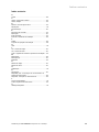
Contents
0020287900_00 sensoCOMFORT Operating and installation instructions 1
Operating and installation
instructions
Contents
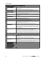
1 Safety.................................................................... 2
1.1 Intended use.......................................................... 2
1.2 General safety information .................................... 2
1.3 -- Safety/regulations......................................... 2
2 Product description............................................. 3
2.1 Which nomenclature is used? ............................... 3
2.2 What is the effect of the frost protection
function? ................................................................ 3
2.3 What do the following temperatures mean? .......... 3
2.4 What is a zone?..................................................... 3
2.5 What is the circulation?.......................................... 3
2.6 What is a fixed value control?................................ 3
2.7 What is meant by "time period"?............................ 3
2.8 What is the effect of the hybrid manager?............. 3
2.9 Preventing malfunctions ........................................ 3
2.10 Setting the heat curve............................................ 4
2.11 Display, control elements and symbols ................. 4
2.12 Operating and display functions ............................ 5
3 -- Electrical installation, set-up................... 15
3.1 Selecting the lines................................................ 15
3.2 Connecting a system control to the ventilation
unit....................................................................... 15
3.3 Installing the system control and outdoor
temperature sensor.............................................. 16
4 -- Using the functional modules, basic
system diagram, start-up.................................. 19
4.1 System without functional modules ..................... 19
4.2 System with FM3 functional module.................... 19
4.3 System with FM5 and FM3 functional
modules ............................................................... 20
4.4 Potential application for the functional
modules ............................................................... 20
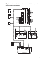
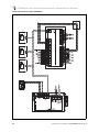
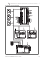
4.5 Terminal assignment for the FM5 functional
module................................................................. 21
4.6 Terminal assignment for the FM3 functional
module................................................................. 22
4.7 Settings for the basic system diagram codes ...... 23
4.8 Combinations of basic system diagram and
configuration of functional modules ..................... 25
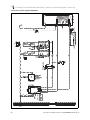
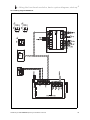
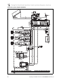
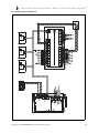
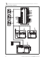
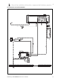
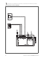
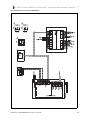
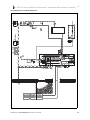
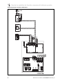
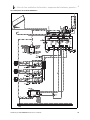
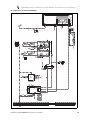
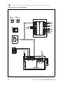
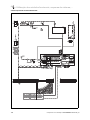
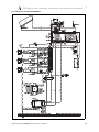
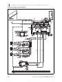
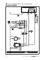
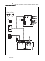
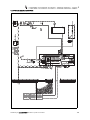
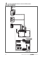
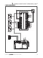
4.9 Basic system diagram and wiring diagram .......... 26
5 -- Start-up...................................................... 43
5.1 Prerequisites for starting up................................. 43
5.2 Running the installation assistants ...................... 43
5.3 Changing the settings later.................................. 43
6 Fault and maintenance messages ................... 43
6.1 Fault..................................................................... 43
6.2 Fault message ..................................................... 43
6.3 Maintenance message ........................................ 43
7 Information about the product ......................... 43
7.1 Observing and storing other applicable
documents ........................................................... 43
7.2 Validity of the instructions.................................... 43
7.3 Data plate ............................................................ 43
7.4 Serial number ...................................................... 44
7.5 CE marking.......................................................... 44
7.6 Guarantee and customer service ........................ 44
7.7 Recycling and disposal........................................ 44
7.8 Product data in accordance with EU
Ordinance no. 811/2013, 812/2013..................... 44
7.9 Technical data – System control.......................... 44
Appendix ............................................................................45
A Troubleshooting, maintenance message........ 45
A.1 Troubleshooting................................................... 45
A.2 Maintenance messages....................................... 45
B -- Troubleshooting, maintenance
message ............................................................. 45
B.1 Troubleshooting................................................... 45
B.2 Troubleshooting................................................... 46
B.3 Maintenance messages....................................... 47
Index ................................................................................... 48

1 Safety
2 Operating and installation instructions sensoCOMFORT 0020287900_00
1 Safety
1.1 Intended use
In the event of inappropriate or improper use,
damage to the product and other property
may arise.
The product is intended for using an eBUS
interface to control a heating installation with
heat generators from the same manufacturer.
The system control controls based on the
installed system:
– Heating
– Cooling
– Ventilation
– Domestic hot water generation
– Circulation
Intended use includes the following:
– Observance of all other applicable docu-
ments for the product and any other sys-
tem components
– installing and setting up the product in ac-
cordance with the product and system ap-
proval
Intended use also covers installation in ac-
cordance with the IP code.
This product can be used by children aged
from 8 years and above and persons with
reduced physical, sensory or mental capabil-
ities or lack of experience and knowledge if
they have been given supervision or instruc-
tion concerning use of the product in a safe
way and understand the hazards involved.
Children must not play with the product.
Cleaning and user maintenance work must
not be carried out by children unless they are
supervised.
Any other use that is not specified in these
instructions, or use beyond that specified in
this document, shall be considered improper
use.
1.2 General safety information
1.2.1 Risk caused by inadequate
qualifications
The following work must only be carried out
by competent persons who are sufficiently
qualified to do so:
– Set-up
– Dismantling
– Installation
– Start-up
– Decommissioning
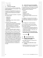
▶ Proceed in accordance with current tech-
nology.
Work and functions that must only be car-
ried out or set by the competent person are
marked by the symbol.
1.2.2 Danger caused by improper
operation
Improper operation may present a danger to
you and others, and cause material damage.
▶ Carefully read the enclosed instructions
and all other applicable documents, par-
ticularly the "Safety" section and the warn-
ings.
▶ As the end user, you should only carry out
those activities for which these instruc-
tions provide instructions and that are not
marked with the symbol.
1.3 -- Safety/regulations
1.3.1 Risk of material damage caused by
frost
▶ Do not install the product in rooms prone
to frost.
1.3.2 Regulations (directives, laws,
standards)
▶ Observe the national regulations, stand-
ards, directives, ordinances and laws.

Product description 2
0020287900_00 sensoCOMFORT Operating and installation instructions 3
2 Product description
2.1 Which nomenclature is used?
– System control: Instead of VRC 720
– Remote control: Instead of VR 92
– FM3 or FM3 functional module: Instead of VR 70
– FM5 or FM5 functional module: Instead of VR 71
2.2 What is the effect of the frost protection
function?
The frost protection function protects the heating installation
and flat from frost damage.
At outdoor temperatures
– Below 4 °C for longer than four hours, the system control
switches the heat generator on and regulates the target
room temperature to at least 5 °C.
– Above 4 °C, the system control does not switch the heat
generator on, but it monitors the outdoor temperature.
2.3 What do the following temperatures mean?
Desired temp. is the temperature to which you want to heat
up the living rooms.
Set-back temp. is the level below which the temperature
in the living rooms does not fall when outside of the time
periods.
Flow temp. is the temperature at which the heating water
leaves the heat generator.
2.4 What is a zone?
A building can be divided into multiple areas, which are
known as zones. A different requirement can be placed on
the heating installation in each zone.
Examples for dividing into zones:
– Underfloor heating (zone 1) and panel radiator heating
(zone 2) are available in one building.
– A building is made up of several self-contained residen-
tial units. Each residential unit has its own zone.
2.5 What is the circulation?
An additional water pipe is connected to the domestic hot
water pipe and forms a circuit with the domestic hot water
cylinder. A circulation pump facilitates the continuous circu-
lation of domestic hot water through the pipework system
which means that hot water is immediately available, even at
more distant draw-off points.
2.6 What is a fixed value control?
The system control regulates the flow temperature to two
fixed temperatures, which are independent from the room or
outdoor temperature. This control is suitable for a door air
curtain or swimming pool heating, for example.
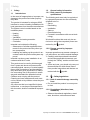
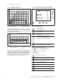
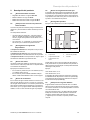
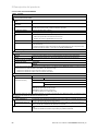
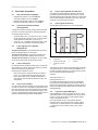
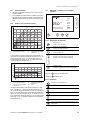
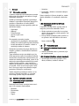
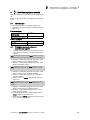
2.7 What is meant by "time period"?
Example of heating mode in the mode: Time-controlled
24 °C
18:0016:30
22:30
16 °C
21 °C
20:00
A
B
5
1
2
3
4
A Time
B Temperature
1 Desired temperature
2 Set-back temperature
3 Time period 2
4 Outside of the time
periods
5 Time period 1
You can divide a day up into several time periods (3) and (5).
Each time period can comprise an individual start time and
end time. The time periods must not overlap. You can assign
a different desired temperature (1) to each time period.
Example:
16:30 to 18:00; 21 °C
20:00 to 22:30; 24 °C
The system control regulates the living rooms to the desired
temperature within the time periods. In the times outside of
the time periods (4), the system control regulates the living
rooms to the lower set-back temperature (2) that is set.
2.8 What is the effect of the hybrid manager?
The hybrid manager calculates whether the heat pump or
the additional boiler covers the heat demand cost-effectively.
The decision-making criteria are the set tariffs in relation to
the heat demand.
To ensure that the heat pump and the additional boiler
can work effectively, you must enter the tariffs correctly.
See table SETTINGS menu item (→ Page 8). Otherwise,
increases costs may arise.
2.9 Preventing malfunctions
▶ Do not cover the system control with furniture, curtains or
other objects.
▶ If the system control is installed in the living room, open
all of the thermostatic radiator valves in this room fully.

2 Product description
4 Operating and installation instructions sensoCOMFORT 0020287900_00
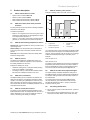
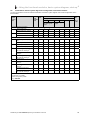
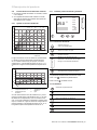
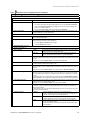
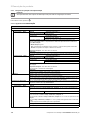
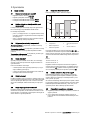
2.10 Setting the heat curve
A
B
15 10 5 0 -5 -10 -15 -20
20
30
40
50
60
70
80
90
1.2
1.5
1.822.533.54
0.8
1.0
0.4
0.2
0.1
0.6
A Outside temperature °C B Target flow temperature
°C
The figure shows the possible heat curves of 0.1 to 4.0 for a
target room temperature of 20 °C. If, for example, heat curve
0.4 is selected, a flow temperature of 40 °C is maintained at
an outdoor temperature of -15 °C.
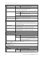
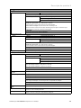
A
B
CD
18
22
20
0.4
70
60
50
40
30
15 10 5 0 -5 -10 -15 -20
A Outdoor temperature °C
B Target flow temperature
°C
C Target room temperat-
ure °C
D Axis a
If the heat curve 0.4 is selected and 21 °C is specified for the
target room temperature, the heat curve is then translated,
as shown in the figure. The heat curve is displaced accord-
ing to the value of the target room temperature along axis a
which is angled at 45°. At an outdoor temperature of -15 °C,
the control system provides a flow temperature of 45 °C.
2.11 Display, control elements and symbols
ĮİŰ
ĬĪƀ
ĬįŀĪ
ƀ
īĬƀ
2.11.1 Control elements
– Calling up the menu
– Back to the main menu
– Confirming a selection/change
– Saving set values
– One level back
– Cancelling input
– Navigating through the menu structure
– Reducing or increasing the set value
– Navigating to individual numbers/letters
– Calling up help
– Calling up the time programme assistant
Active control elements light up green.
Press once: You access the basic display.
Press twice: You access the menu.
2.11.2 Symbols
Time-controlled heating active
Button lock active
Maintenance required
Fault in the heating installation
Contact the competent person
Noise reduction mode active
Most energy-efficient heating mode active

Product description 2
0020287900_00 sensoCOMFORT Operating and installation instructions 5
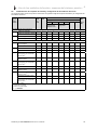
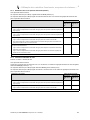
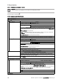
2.12 Operating and display functions
Note
The functions described in this section are not available for all system configurations.
To call up the menu, press twice.
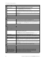
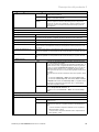
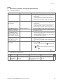
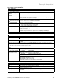
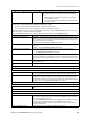
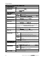
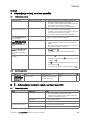
2.12.1 CONTROL menu item
MENU → CONTROL
→ Zone
→ Name of zone Changing the name Zone 1, which was set at the factory
→ Heating → Mode: → Manual → Desired temperature: °C
Uninterrupted retention of the desired temperature
→ Time-contr. → Weekly planner
→ Set-back temperature: °C
Weekly planner: Up to 12 time periods and desired temperatures can be set per day
The competent person sets how the heating installation behaves outside of the time period in the
Set-back mode: function.
In Set-back mode: means:
– Eco: The heating is switched off outside of the time periods. Frost protection is activated.
– Normal: The set-back temperature applies outside of the time periods.
Desired temperature: °C: Applies within the time periods
→ Off
Heating is switched off, domestic hot water continues to be available, frost protection is activated
→ Cooling → Mode: → Manual → Desired temperature: °C
Uninterrupted retention of the desired temperature
→ Time-contr. → Weekly planner
→ Desired temperature: °C
Weekly planner: Up to 12 time periods can be set per day; cooling is switched off outside of the
time periods
Desired temperature: °C: Applies within the time periods
Cooling is switched off outside of the time periods
→ Off
Cooling is switched off, domestic hot water remains available
→ Absence → All: Applies only to any zones within the specified time period
→ Zone: Applies for the selected zone in the specified time period
Heating and domestic hot water mode is switched off, existing ventilation operates at the lowest
ventilation level, frost protection is activated
→ Cooling for several days Cooling mode is activated in the specified time period, cooling mode and desired temperature are
used from the Cooling function
→ Fixed value control, circuit 1
→ Heating → Mode: → Manual
Uninterrupted retention of the Target flow temp., desired: °C that the competent person set.
→ Time-contr. → Weekly planner
Weekly planner: Up to 12 time periods can be set per day
Within the time period, the Target flow temp., desired: °C is used.
Outside of the time periods, the Target flow temp., set-back: °C is used or the heating circuit is
switched off.
At a Target flow temp., set-back: °C = 0 °C, the frost protection can no longer be guaranteed.
The competent person sets both of these temperatures.
→ Off
The heating circuit is switched off.
→ Domestic hot water

2 Product description
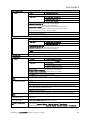
6 Operating and installation instructions sensoCOMFORT 0020287900_00
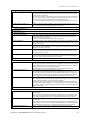
MENU → CONTROL
→ Mode: → Manual → DHW temperature
Uninterrupted retention of the domestic hot water temperature
→ Time-contr. → Domestic hot water weekly planner
→ DHW temperature: °C
→ Circulation weekly planner
Domestic hot water weekly planner: Up to three time periods can be set per day
DHW temperature: °C: Applies within the time periods
Domestic hot water mode is switched off outside of the time periods
Circulation weekly planner: Up to three time periods can be set per day
The circulation pump pumps hot water to the draw-off points within the time periods
Outside of the time periods, the circulation pump is switched off
→ Off
Domestic hot water mode is switched off
→ DHW circuit 1
→ Mode: → Manual → DHW temperature: °C
Uninterrupted retention of the domestic hot water temperature
→ Time-contr. → Domestic hot water weekly planner
→ DHW temperature: °C
Domestic hot water weekly planner: Up to three time periods can be set per day
DHW temperature: °C: Applies within the time periods
Domestic hot water mode is switched off outside of the time periods
→ Off
Domestic hot water mode is switched off
→ DHW boost Heating up the water in the cylinder once
→ Ventilation
→ Mode: → Normal → Normal ventilation level:
Uninterrupted ventilation at ventilation level: Normal
→ Time-contr. → Weekly planner
→ Normal ventilation level:
→ Reduced ventilation level:
Weekly planner: Up to 12 time periods can be set per day
Normal ventilation level:: Applies within the time periods
Reduced ventilation level:: Applies outside of the time periods
→ Reduced
Uninterrupted ventilation at ventilation level: Reduced
→ Air quality sensor 1:
ppm
Measures the CO
2
content of the room air
→ Heat recovery: → On
Uninterrupted recovery of the heat from the extract air
→ Auto
Internal check of whether the outdoor air is guided via the heat recovery or directly into the living
room. See the operating instructions for the ventilation unit.
→ Off
Heat recovery is switched off
→ Air quality limit: ppm The ventilation unit keeps the CO
2
content in the room air below the set value.
→ Ventilation boost Heating mode is switched off for 30 minutes and, if available, the ventilation unit runs at the highest
ventilation level.
→ Humidity prevention → Max. room air humidity: %rel: If the value is exceeded, the dehumidifier switches on. If the value
is not reached, the dehumidifier switches off.
→ Time programme assistant Programming of the desired temperature for Monday–Friday and Saturday–Sunday; the program-
ming applies for the time-controlled Heating Cooling, Domestic hot water, Circulation and Ventil-
ation functions
Overwrites the weekly planner for the Heating, Cooling, Domestic hot water, Circulation and
Ventilation functions

Product description 2
0020287900_00 sensoCOMFORT Operating and installation instructions 7
MENU → CONTROL
→ Green iQ: Switching on the most energy-efficient heating mode, if your installation supports this.
→ Sytem off Installation is switched off. Frost protection and, if available, ventilation remain activated at the lowest
level.
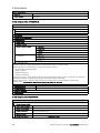
2.12.2 INFORMATION menu item
MENU → INFORMATION
→ Current temperatures
→ Zone
→ DHW temperature
→ DHW circuit 1
→ Water pressure: bar
→ Current room air humidity
→ Energy data
→ Solar yield
→ Environmental yield
→ Power consumption → Heating
→ Domestic hot water
→ Cooling
→ Installation
→ Fuel consumption → Heating
→ Domestic hot water
→ Installation
→ Heat recovery
Display of energy consumption and energy yield
In the display and in the app that can also be used, the control displays values for the energy consumption and/or the energy yield.
The control displays an estimation of the values for the installation. Among other things, the values are influenced by the following:
– The installation/design of the heating installation
– User behaviour
– Seasonal environmental conditions
– Tolerances and components
External components, such as external heating pumps or valves, and other consumers and appliances in the household are still not
taken into consideration.
The deviations between the energy consumption or energy yield that is displayed and the actual energy consumption or energy yield
may be significant.
The specifications for the energy consumption or energy yield are not suitable to be used to create or compare energy billing.
The following can be read: Current month, Last month, Current year, Last year, Total
→ Burner status:
→ Control elements Explanation of the control elements
→ Menu introduction Explanation of the menu structure
→ Competent person contact info
→ Serial number

2 Product description
8 Operating and installation instructions sensoCOMFORT 0020287900_00
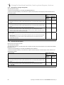
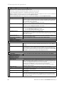
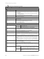
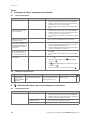
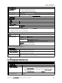
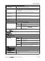
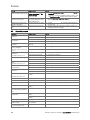
2.12.3 SETTINGS menu item
MENU → SETTINGS
→ Installer level
→ Enter access code Access to the installer level, factory setting: 00
→ Competent person con-
tact info
Entering contact details
→ Service date: Enter the next service date for a connected component, e.g. heat generator, heat pump, ventilation
unit
→ Fault history Faults are listed in chronological order
→ Installation configuration Functions (→ Installation configuration menu item)
→ Sensor/actuator test Selecting a connected functional module and
– carrying out a function check of the actuators.
– Carry out a plausibility check of the sensors.
→ Noise reduction mode Set the time programme in order to reduce the noise level.
→ Screed drying Activate the Screed drying profile function for freshly laid screed in accordance with the construc-
tion regulations.
The system control regulates the flow temperature independently of the outdoor temperature. Setting
screed drying (→ Installation configuration menu item)
→ Change code
→ Language, time, display
→ Language:
→ Date: After the power is switched off, the date is retained for approx. 30 minutes.
→ Time: After the power is switched off, the time is retained for approx. 30 minutes.
→ Display brightness:
→ Daylight saving time: → Automatic
→ Manual
For outdoor temperature sensors with DCF77 receivers, the Daylight saving time: function is not used. The conversion to sum-
mer/winter time takes place via the DCF77 signal. The change takes place:
– On the last weekend in March at 02:00 (daylight saving time)
– On the last weekend in October at 03:00 (standard time)
→ Tariffs
→ Tariff for back-up boiler: Enter a gas, oil or electricity tariff
→ Electricity tariff type:
(for heat pump)
→ Single tariff → High tariff:
The costs are always calculated using the high tariff.
→ Dual tariff → Dual tariff weekly planner
→ Low tariff:
Dual tariff weekly planner: Up to 12 time periods can be set per day
High tariff:: Applies within the time periods
Low tariff:: Applies outside of the time periods
The costs are calculated using the high and low tariffs.
The hybrid manager uses the tariffs and the heat demand to calculate the costs for the back-up boiler and the heat pump. The more
cost-effective component is used for the heat generation.
→ Offset
→ Room temperature: K Comparison of the temperature difference between the measured value in the system control and
the value for a reference thermometer in the living room.
→ Outdoor temperature: K Comparison of the temperature difference between the measured value in the outdoor temperature
sensor and the value for a reference thermometer in the living room.
→ Factory settings The system control resets all of the settings to the factory settings and calls up the installation assist-
ant.
Only the competent person can call up the installation assistant.

Product description 2
0020287900_00 sensoCOMFORT Operating and installation instructions 9
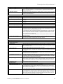
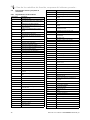
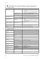
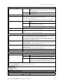
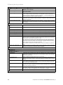
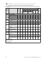
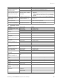
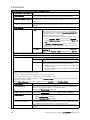
2.12.4 Installation configuration menu item
MENU → SETTINGS → Installer level → Installation configuration
→ Installation
→ Water pressure: bar
→ eBUS components List of eBUS components and their software versions
→ Adaptive heat curve: Automatic fine adjustment of the heat curve. Prerequisite:
– The suitable heat curve for the building is set in the Heat curve: function.
– The correct zone is assigned to the system control or the remote control in the Zone
assignment: function.
– Expanded is selected in the Room temp. mod.: function.
→ Automatic cooling: When a heat pump is connected, the system control automatically switches between heating
mode and cooling mode.
→ Outdoor temp., 24 hr av.: °C
→ Cooling at outdoor temp.: °C Cooling starts once the outdoor temperature (24-hour average) exceeds the set temperature.
→ Source regeneration: The system control switches the Cooling function on and guides the heat from the living
room back to the earth via the heat pump. Prerequisite:
– The Automatic cooling: function has been activated.
– The Absence function is active.
→ Current room air hum.: %rel
→ Current dew point: °C
→ Hybrid manager: → triVAl The heat generator is selected based on the set tariffs in relation to the
heat demand.
→ Bivalence pt The heat generator is selected based on the outdoor temperature (
Heating bivalence point: °C and Alternative point).
→ Heating bivalence point: °C If the outdoor temperature falls below the set value, the system control enables the back-up
boiler to operate in parallel with the heat pump in heating mode.
Prerequisite: Bivalence pt is selected in the Hybrid manager: function.
→ DHW bivalence point: °C If the outdoor temperature falls below the set value, the system control activates the back-up
boiler in parallel with the heat pump.
→ Alternative point: If the outdoor temperature falls below the set value, the system control switches the heat
pump off and the back-up boiler meets the heat demand in heating mode.
Prerequisite: Bivalence point is selected in the Hybrid manager: function.
→ LHM temperature: °C Set a low target flow temperature. If the heat pump fails, the back-up boiler fulfils the heat
demand, which leads to higher heating costs. The end user should recognise that heat loss
means that there is a problem with the heat pump.
The end user can use the Mode: Temporary back-up boiler mode function to enable the
back-up boiler and therefore deactivate the target flow temperature that is set here.
→ Back-up boiler type: Select a type for the heat generator that is also installed. An incorrect selection may lead to
increased costs.
Prerequisite: triVAl is selected in the Hybrid manager: function.
→ ESCO: Define what you want to deactivate when the signal is sent by the energy supply company.
The selection remains deactivated until the energy supply company cancels the signal.
The heat generator ignores the deactivation signal as soon as the frost protection function is
active.
→ Back-up boiler: → Off The back-up boiler does not support the heat pump.
The back-up boiler is activated for the anti-legionella function, frost pro-
tection or de-icing.
→ Heating The back-up boiler supports the heat pump during heating.
The back-up boiler is activated for the anti-legionella function.
→ DHW The back-up boiler supports the heat pump during domestic hot water
generation.
The back-up boiler is activated for frost protection or de-icing.
→ DHW + heat. The back-up boiler supports the heat pump during domestic hot water
generation and heating.
→ Installation flow temperature: °C Measured temperature, e.g. downstream of the low loss header

2 Product description
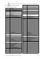
10 Operating and installation instructions sensoCOMFORT 0020287900_00
MENU → SETTINGS → Installer level → Installation configuration
→ Buffer cylinder offset: K In the case of excessive current, the buffer cylinder is heated up to the flow temperature +
set offset via the heat pump. Prerequisite:
– A photovoltaic installation is connected.
– Photovoltaics is activated in the HP control module configuration → MI: function.
→ Actuation reversal: → Off The system control always actuates the heat generators in the sequence
1, 2, 3, etc.
→ On Once a day, the system control sorts the heat generators based on their
actuation time.
The back-up heater is excluded from this sorting.
Prerequisite: The heating installation contains a cascade.
→ Actuation sequence: Sequence in which the system control actuates the heat generators.
Prerequisite: The heating installation contains a cascade.
→ Conf. ext. input: Select whether the external heating circuit is deactivated using a bridge or open terminals.
Prerequisite: The FM5 and/or FM3 functional module is connected.
→ Basic system diagram config.
→ Basic system diagram code: Systems are roughly grouped according to their connected system components. Each group
has a basic system diagram code. Based on the code that is entered, the system control
enables the system-related functions.
You can use the connected components to determine the basic system diagram code for the
installed installation (→ Using the functional modules, basic system diagram, start-up) and
enter this here.
→ FM5 configuration: Each configuration corresponds to a defined terminal assignment (→ Connection assignment
for the FM5 functional module). The terminal assignment determines which functions contain
the inputs and outputs.
Select the configuration that suits the installation that is installed.
→ FM3 configuration: Each configuration corresponds to a defined terminal assignment (→ Connection assignment
for the FM3 functional module). The terminal assignment determines which functions contain
the inputs and outputs.
Select the configuration that suits the installation that is installed.
→ FM3 MO: Select the multi-function output's function assignment.
→ FM5 MO: Select the multi-function output's function assignment.
→ HP control module configuration
→ MO 2: Select the multi-function output's function assignment.
→ MI: → Not connec-
ted
The system control ignores the signal present.
→ 1 x circula-
tion
The end user has pressed the circulation button. The system control
activates the circulation pump for a short time period.
→ Photovoltaics In the case of excessive current, a signal is present and the system con-
trol activates the DHW boost function once. If the signal persists, the
buffer cylinder is charged to the flow temperature + buffer cylinder offset
until the signal at the heat pump drops off again.
The system control queries whether a signal is present at the heat pump's input. For example:
–
aroTHERM input: MI for the heat pump control module
– flexoTHERM input: X41, terminal in the functional drawing
→ Heat generator 1
→ Heat pump 1
→ HP control module
→ Status:
→ Current flow temperature: °C
→ Circuit 1
→ Circuit type: → Inactive The heating circuit is not being used.
→ Heating The heating circuit is being used to heat and is weather-compensated.
Depending on the basic system diagram, the heating circuit may be a
mixing circuit or a direct circuit.
→ Fixed value The heating circuit is used for heating and is maintained at a fixed target
flow temperature.
→ DHW The heating circuit is being used as a domestic hot water circuit for an
additional cylinder.

Product description 2
0020287900_00 sensoCOMFORT Operating and installation instructions 11
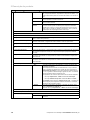
MENU → SETTINGS → Installer level → Installation configuration
→ Circuit type: → Increase in
return
The heating circuit is used to increase the return flow. The increase in
return prevents an excessive temperature difference between the heat-
ing flow and return, and protects against corrosion in the floor-standing
boiler when the dew point is not reached for an extended period.
→ Status:
→ Target flow temperature: °C
→ Actual flow temperature: °C
→ Target return temperature: °C Select a temperature at which the heating water should flow back into the floor-standing
boiler.
→ OT switch-off threshold: °C Enter the upper limit for the outdoor temperature. If the outdoor temperature rises above the
set value, the system control deactivates heating mode.
→ Target flow temp., desired: °C Select the temperature for the fixed value circuit which applies within the time period.
→ Target flow temp., set-back: °C Select the temperature for the fixed value circuit which applies outside of the time period.
→ Heat curve: The heat curve (→ section "Product description") is the dependence of the flow temperature
on the outdoor temperature for the desired temperature (target room temperature).
→ Min. target flow temperature:°C Enter the lower limit for the target flow temperature. The system control compares the set
value with the calculated target flow temperature, and regulates to the larger of these values.
→ Max. target flow temperature:°C Enter the upper limit for the target flow temperature. The system control compares the set
value with the calculated target flow temperature, and regulates to the smaller of these val-
ues.
→ Set-back mode:
→ Eco The heating function is switched off and the frost protection function is
activated.
At outdoor temperatures that are below 4 °C for longer than four hours,
the system control switches the heat generator on and regulates to the
Set-back temperature: °C. At an outdoor temperature above 4 °C, the
system control switches the heat generator off. The monitoring of the
outdoor temperature remains active.
Heating circuit behaviour outside of the time periods. Prerequisite:
– Time-contr. is activated in the Heating → Mode: function.
– Active or Inactive is activated in the Room temp. mod.: function.
If Expanded is activated in the Room temp. mod.:, the system control
regulates to the target room temperature 5 °C independently of the out-
door temperature.
→ Normal The heating function is switched on. The system control regulates to the
Set-back temperature: °C.
Prerequisite: Time-contr. is activated in the Heating → Mode: function.
The behaviour can be adjusted separately for each heating circuit.
→ Room temp. mod.:
→ Inactive
→ Active Adjusting the flow temperature based on the current room temperature.
→ Expanded Adjusting the flow temperature based on the current room temperature.
The system control also activates/deactivates the zone.
– The zone is deactivated: Current room temperature + 2/16 K > set
room temperature
– Zone is activated: Current room temperature < set room temperature
- 3/16 K
The installed temperature sensor measures the current room temperature. The system control calculates a new target room temper-
ature that is used to adjust the flow temperature.
– Difference = Set target room temperature - current room temperature
–
New target room temperature = Set target room temperature + difference
Prerequisite: In the Zone assignment: function, the system control and/or the remote control is assigned to the zone in which the
system control or remote control is installed.
The Room temp. mod.: function is ineffective if No assignmt is activated in the Zone assignment: function.
→ Cooling possible: Prerequisite: A heat pump is connected.
→ Dew point monitoring: The system control compares the set minimum cooling target flow temperature with the cur-
rent dew point + set dew point offset. The system control selects the higher temperature for
the target flow temperature in order to prevent condensate.
Prerequisite: The Cooling possible: function has been activated.

2 Product description
12 Operating and installation instructions sensoCOMFORT 0020287900_00
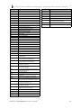
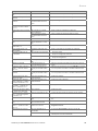
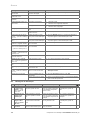
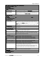
MENU → SETTINGS → Installer level → Installation configuration
→ Min. cooling targ. flow temp.: °C The system control regulates the heating circuit to the Min. cooling targ. flow temp.: °C.
Prerequisite: The Cooling possible: function has been activated.
→ Dew point offset: K Safety margin that is added to the current dew point. Prerequisite:
– The Cooling possible: function has been activated.
– The Dew point monitoring: function has been activated.
→ Ext. heat demand: Display showing whether a heat demand is present at an external input.
When installing an FM5 or FM3 functional module, external inputs are available, depending
on the configuration. You can connect an external zone controller, for example, to this ex-
ternal input.
→ DHW temperature: °C Desired temperature at the withdrawal point. The heating circuit is used as a domestic hot
water circuit.
→ Actual cylinder temperature: °C The heating circuit is used as a domestic hot water circuit.
→ Pump status:
→ Mixing valve status: %
→ Zone
→ Zone activated: Deactivate zones that are not required. All existing zones appear in the display. Prerequisite:
The existing heating circuits are activated in the Circuit type: function.
→ Zone assignment: Assign the system control and/or remote control to the selected zone. The system control
and/or remote control must be installed in the selected zone. The control system also uses
the room temperature sensor for the assigned unit. The remote control uses all of the val-
ues for the assigned zone. The Room temp. mod.: function is ineffective if you have not as-
signed any zones.
→ Zone valve status:
→ Domestic hot water
→ Cylinder: If there is an existing domestic hot water cylinder, the Active setting must be selected.
→ Target flow temperature: °C
→ Cylinder charging pump:
→ Circulation pump:
→ Anti-legio. day: Define the days on which you want the anti-legionella function to run. On these days, the
water temperature is increased to above 60 °C. The circulation pump is activated. The func-
tion ends after 120 minutes at the latest.
If the Absence function is activated, the anti-legionella function is not carried out. As soon
as the Absence function ends, the anti-legionella function is carried out.
Heating installations with heat pumps use the back-up boiler for legionella protection.
→ Anti-legio. time: Define the time at which you want the anti-legionella function to run.
→ Cylinder charging hysteresis: K The cylinder charging starts as soon as cylinder temperature < desired temperature - hyster-
esis value.
→ Cylinder charging offset: K Desired temperature + offset = flow temperature for the domestic hot water cylinder.
→ Max. cyl. charging time: Setting the maximum time at which the domestic hot water cylinder can be charged without
interruption. If the maximum time or the target temperature is reached, the system control
enables the heating function. The setting Off means that the cylinder charging time is not
restricted.
→ Cyl. charg. anti-cycl. time: min Setting the time period during which the cylinder charging is blocked after the maximum cyl-
inder charging time has elapsed. During the blocked time, the system control enables the
heating function.
→ Parallel cylinder charging: When charging the domestic hot water cylinder, the mixing circuit is heated in parallel. The
non-mixed heating circuit is always switched off during cylinder charging.
→ Buffer cylinder
→ Cylinder temp., top: °C Actual temperature in the upper section of the buffer cylinder
→ Cylinder temp., bottom: °C Actual temperature in the lower section of the buffer cylinder
→ DHW temp. sensor, top: °C Actual temperature in the upper part of the domestic hot water section of the buffer cylinder
→ DHW temp. sensor, bottom: °C Actual temperature in the lower part of the domestic hot water section of the buffer cylinder
→ Heat. temp. sensor, top: °C Actual temperature in the upper part of the heating section of the buffer cylinder
→ Heat. temp. sensor, bottom: °C Actual temperature in the lower part of the heating section of the buffer cylinder
→ Solar cylinder, bottom: °C Actual temperature in the lower section of the solar cylinder

Product description 2
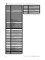
0020287900_00 sensoCOMFORT Operating and installation instructions 13
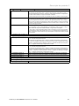
MENU → SETTINGS → Installer level → Installation configuration
→ Max. DHW targ. flow temp..: °C Setting the maximum buffer cylinder target flow temperature for the domestic hot water sta-
tion. The set maximum target flow temperature must be lower than the maximum flow tem-
perature for the heat generator.
If the maximum target flow temperature is set too low, the domestic hot water station cannot
reach the target cylinder temperature. While the target cylinder temperature is not reached,
the system control does not enable the heat generator for heating mode.
You can find the maximum flow temperature in the installation instructions for the heat gen-
erator.
→ Max. temp. of cylinder 1: °C Setting the maximum cylinder temperature. The solar circuit stops the cylinder charging as
soon as the maximum cylinder temperature has been reached.
→ Solar circuit
→ Collector temperature: °C
→ Solar pump:
→ Solar yield sensor: °C
→ Solar flow rate quantity: Entering the volume flow to calculate the solar yield. If a solar pump station is installed, the
system control ignores that value that has been entered and uses the volume flow that is
supplied from the solar pump station.
The value 0 means the automatic recording of the volume flow.
→ Solar pump kick: Accelerated recording of the collector temperature. When the function is activated, the solar
pump is switched on for a short time and the heated solar fluid is transported to the measur-
ing point more quickly.
→ Solar circuit prot. function: °C Setting the maximum temperature that must not be exceeded in the solar circuit. If the max-
imum temperature at the collector sensor is exceeded, the solar pump switches off to protect
the solar circuit against overheating.
→ Min. collector temperature: °C Setting the minimum collector temperature that is required for the solar charging switch-on
differential. The differential temperature control can only start once the minimum collector
temperature has been reached.
→ Purging time: min Setting the time period during which the solar circuit is purged. The system control stops the
function once the specified purging time has elapsed, the solar circuit protection function is
active or the max. cylinder temperature has been exceeded.
→ Current flow rate: l/min Current volume flow of the solar pump station
→ Solar cylinder 1
→ Switch-on differential: K Setting the differential value for starting the solar charging.
If the temperature difference between the cylinder temperature sensor at the bottom and the
collector temperature sensor is greater than the set differential value and the set minimum
collector temperature, the cylinder charging is started.
The differential value can be defined separately for two connected solar cylinders.
→ Switch-off differential: K Setting the differential value for stopping the solar charging.
If the temperature difference between the bottom cylinder temperature sensor and the col-
lector temperature sensor is smaller than the set differential value and the set minimum col-
lector temperature, the cylinder charging is stopped. The switch-off differential temperature
value must be at least 1 K less than the set switch-on differential temperature value.
→ Maximum temperature: °C Set the maximum cylinder charging temperature for the cylinder protection.
If the temperature at the bottom cylinder temperature sensor is higher than the set maximum
cylinder charging temperature, the solar charging is interrupted.
The solar charging is only enabled again once the temperature at the bottom cylinder tem-
perature sensor has fallen by between 1.5 K and 9 K, depending on the maximum temperat-
ure. The set maximum temperature must not exceed the maximum permissible cylinder tem-
perature of the cylinder.
→ Solar cylinder, bottom: °C
→ 2nd diff. temp control
→ Switch-on differential: K Setting the differential value for starting the temperature difference control, such as solar
heating support.
If the temperature difference between differential temperature sensor 1 and differential tem-
perature sensor 2 is greater than the set switch-on differential and the set minimum temper-
ature at differential temperature sensor 1, the differential temperature control is started.
→ Switch-off differential: K Setting the differential value for stopping the temperature difference control, such as solar
heating support.
If the temperature difference between differential temperature sensor 1 and differential tem-
perature sensor 2 is lower than the set switch-off differential and the set maximum temperat-
ure at differential temperature sensor 2, the differential temperature control is stopped.
→ Minimum temperature: °C Setting the minimum temperature for starting the differential temperature control.

2 Product description
14 Operating and installation instructions sensoCOMFORT 0020287900_00
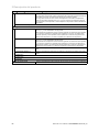
MENU → SETTINGS → Installer level → Installation configuration
→ Maximum temperature: °C Setting the maximum temperature for stopping the differential temperature control.
→ Diff. temp. sensor 1:
→ Diff. temp. sensor 2:
→ Diff. temp. sensor output:
→ Screed drying profile Setting target flow temperature per day in accordance with the construction regulations

-- Electrical installation, set-up
3
0020287900_00 sensoCOMFORT Operating and installation instructions 15
3 -- Electrical installation, set-up
Only qualified electricians may carry out the electrical install-
ation.
The heating installation must be decommissioned before
work is carried out on it.
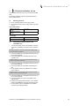
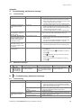
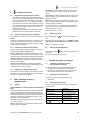
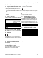
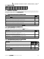
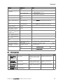
3.1 Selecting the lines
▶ Do not use flexible lines for power supply cables.
▶ Use sheathed cables for power supply cables (e.g. NYM
3 x 1.5).
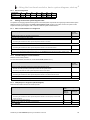
Line cross-section
eBUS line (extra-low
voltage)
≥ 0.75 mm²
Sensor line (extra low
voltage)
≥ 0.75 mm²
Line length
Sensor lines
≤ 50 m
Bus lines
≤ 125 m
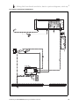
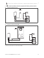
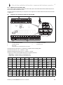
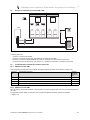
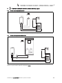
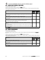
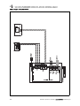
3.2 Connecting a system control to the
ventilation unit
1. Connect the system control to the ventilation unit as de-
scribed in the installation instructions for the ventilation
unit.
Condition: Ventilation unit connected to the eBUS without VR 32, Ventila-
tion unit without eBUS heat generator
▶ Connect the eBUS line to the eBUS terminals in the sys-
tem control's wall base.
▶ Connect the eBUS line to the eBUS terminals on the
ventilation unit.
Condition: Ventilation unit connected to the eBUS with VR 32, Ventilation
unit with up to two eBUS heat generators
▶ Connect the eBUS line to the eBUS terminals in the sys-
tem control's wall base.
▶ Connect the eBUS line to the eBUS of the heat gener-
ator.
▶ Set the address switch for the VR 32 in the ventilation
unit to position 3.
Condition: Ventilation unit connected to the eBUS with VR 32, Ventilation
unit with more than two eBUS heat generators
▶ Connect the eBUS line to the eBUS terminals in the sys-
tem control's wall base.
▶ Connect the eBUS line to the common eBUS on the
heat generator.
▶ Determine the highest possible position on the address
switches of the VR 32 for the connected heat generator.
▶ Set the address switch of the VR 32 in the ventilation
unit to the second highest position.

3
-- Electrical installation, set-up
16 Operating and installation instructions sensoCOMFORT 0020287900_00
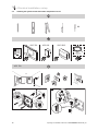
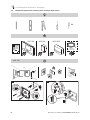
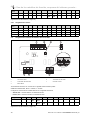
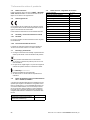
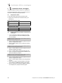
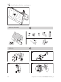
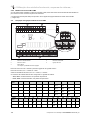
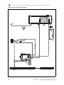
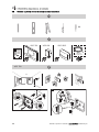
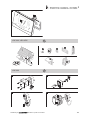
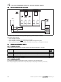
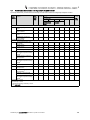
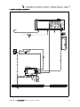
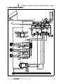
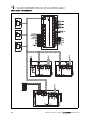
3.3 Installing the system control and outdoor temperature sensor
Ø6
VRC 720 VRC 693 VRC 9535
H05VVF
2 x 0,75 mm²
VRC 720
1,5 m
Ø6
60
1.
≤25 mm
A
B
C
2.

-- Electrical installation, set-up
3
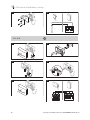
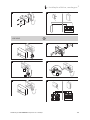
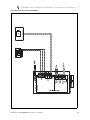
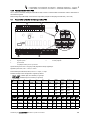
0020287900_00 sensoCOMFORT Operating and installation instructions 17
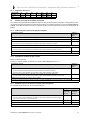
A
B
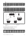
3.
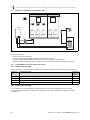
VRC 693, VRC 9535
E
W
S
N
≥ 2,5 m
VRC 693
1.
Ø6
2.
3.
B
A
4.
B
A

3
-- Electrical installation, set-up
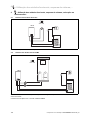
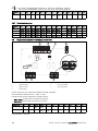
18 Operating and installation instructions sensoCOMFORT 0020287900_00
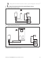
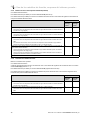
5.
6.
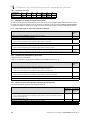
VRC 9535
D
C
F
O
T
AF
1.
Ø6
D
C
F
O
T
AF
2.
D
C
F
O
T
AF
3.
B
A
D
C
F
O
T
AF
4.
D
C
F
O
T
AF
B
A
D
C
F
O
T
AF
5.
6.
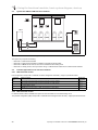
A página está carregando...
A página está carregando...
A página está carregando...
A página está carregando...
A página está carregando...
A página está carregando...
A página está carregando...
A página está carregando...
A página está carregando...
A página está carregando...
A página está carregando...
A página está carregando...
A página está carregando...
A página está carregando...
A página está carregando...
A página está carregando...
A página está carregando...
A página está carregando...
A página está carregando...
A página está carregando...
A página está carregando...
A página está carregando...
A página está carregando...
A página está carregando...
A página está carregando...
A página está carregando...
A página está carregando...
A página está carregando...
A página está carregando...
A página está carregando...
A página está carregando...
A página está carregando...
A página está carregando...
A página está carregando...
A página está carregando...
A página está carregando...
A página está carregando...
A página está carregando...
A página está carregando...
A página está carregando...
A página está carregando...
A página está carregando...
A página está carregando...
A página está carregando...
A página está carregando...
A página está carregando...
A página está carregando...
A página está carregando...
A página está carregando...
A página está carregando...
A página está carregando...
A página está carregando...
A página está carregando...
A página está carregando...
A página está carregando...
A página está carregando...
A página está carregando...
A página está carregando...
A página está carregando...
A página está carregando...
A página está carregando...
A página está carregando...
A página está carregando...
A página está carregando...
A página está carregando...
A página está carregando...
A página está carregando...
A página está carregando...
A página está carregando...
A página está carregando...
A página está carregando...
A página está carregando...
A página está carregando...
A página está carregando...
A página está carregando...
A página está carregando...
A página está carregando...
A página está carregando...
A página está carregando...
A página está carregando...
A página está carregando...
A página está carregando...
A página está carregando...
A página está carregando...
A página está carregando...
A página está carregando...
A página está carregando...
A página está carregando...
A página está carregando...
A página está carregando...
A página está carregando...
A página está carregando...
A página está carregando...
A página está carregando...
A página está carregando...
A página está carregando...
A página está carregando...
A página está carregando...
A página está carregando...
A página está carregando...
A página está carregando...
A página está carregando...
A página está carregando...
A página está carregando...
A página está carregando...
A página está carregando...
A página está carregando...
A página está carregando...
A página está carregando...
A página está carregando...
A página está carregando...
A página está carregando...
A página está carregando...
A página está carregando...
A página está carregando...
A página está carregando...
A página está carregando...
A página está carregando...
A página está carregando...
A página está carregando...
A página está carregando...
A página está carregando...
A página está carregando...
A página está carregando...
A página está carregando...
A página está carregando...
A página está carregando...
A página está carregando...
A página está carregando...
A página está carregando...
A página está carregando...
A página está carregando...
A página está carregando...
A página está carregando...
A página está carregando...
A página está carregando...
A página está carregando...
A página está carregando...
A página está carregando...
A página está carregando...
A página está carregando...
A página está carregando...
A página está carregando...
A página está carregando...
A página está carregando...
A página está carregando...
A página está carregando...
A página está carregando...
A página está carregando...
A página está carregando...
A página está carregando...
A página está carregando...
A página está carregando...
A página está carregando...
A página está carregando...
A página está carregando...
A página está carregando...
A página está carregando...
A página está carregando...
A página está carregando...
A página está carregando...
A página está carregando...
A página está carregando...
A página está carregando...
A página está carregando...
A página está carregando...
A página está carregando...
A página está carregando...
A página está carregando...
A página está carregando...
A página está carregando...
A página está carregando...
A página está carregando...
A página está carregando...
A página está carregando...
A página está carregando...
A página está carregando...
A página está carregando...
A página está carregando...
A página está carregando...
-
 1
1
-
 2
2
-
 3
3
-
 4
4
-
 5
5
-
 6
6
-
 7
7
-
 8
8
-
 9
9
-
 10
10
-
 11
11
-
 12
12
-
 13
13
-
 14
14
-
 15
15
-
 16
16
-
 17
17
-
 18
18
-
 19
19
-
 20
20
-
 21
21
-
 22
22
-
 23
23
-
 24
24
-
 25
25
-
 26
26
-
 27
27
-
 28
28
-
 29
29
-
 30
30
-
 31
31
-
 32
32
-
 33
33
-
 34
34
-
 35
35
-
 36
36
-
 37
37
-
 38
38
-
 39
39
-
 40
40
-
 41
41
-
 42
42
-
 43
43
-
 44
44
-
 45
45
-
 46
46
-
 47
47
-
 48
48
-
 49
49
-
 50
50
-
 51
51
-
 52
52
-
 53
53
-
 54
54
-
 55
55
-
 56
56
-
 57
57
-
 58
58
-
 59
59
-
 60
60
-
 61
61
-
 62
62
-
 63
63
-
 64
64
-
 65
65
-
 66
66
-
 67
67
-
 68
68
-
 69
69
-
 70
70
-
 71
71
-
 72
72
-
 73
73
-
 74
74
-
 75
75
-
 76
76
-
 77
77
-
 78
78
-
 79
79
-
 80
80
-
 81
81
-
 82
82
-
 83
83
-
 84
84
-
 85
85
-
 86
86
-
 87
87
-
 88
88
-
 89
89
-
 90
90
-
 91
91
-
 92
92
-
 93
93
-
 94
94
-
 95
95
-
 96
96
-
 97
97
-
 98
98
-
 99
99
-
 100
100
-
 101
101
-
 102
102
-
 103
103
-
 104
104
-
 105
105
-
 106
106
-
 107
107
-
 108
108
-
 109
109
-
 110
110
-
 111
111
-
 112
112
-
 113
113
-
 114
114
-
 115
115
-
 116
116
-
 117
117
-
 118
118
-
 119
119
-
 120
120
-
 121
121
-
 122
122
-
 123
123
-
 124
124
-
 125
125
-
 126
126
-
 127
127
-
 128
128
-
 129
129
-
 130
130
-
 131
131
-
 132
132
-
 133
133
-
 134
134
-
 135
135
-
 136
136
-
 137
137
-
 138
138
-
 139
139
-
 140
140
-
 141
141
-
 142
142
-
 143
143
-
 144
144
-
 145
145
-
 146
146
-
 147
147
-
 148
148
-
 149
149
-
 150
150
-
 151
151
-
 152
152
-
 153
153
-
 154
154
-
 155
155
-
 156
156
-
 157
157
-
 158
158
-
 159
159
-
 160
160
-
 161
161
-
 162
162
-
 163
163
-
 164
164
-
 165
165
-
 166
166
-
 167
167
-
 168
168
-
 169
169
-
 170
170
-
 171
171
-
 172
172
-
 173
173
-
 174
174
-
 175
175
-
 176
176
-
 177
177
-
 178
178
-
 179
179
-
 180
180
-
 181
181
-
 182
182
-
 183
183
-
 184
184
-
 185
185
-
 186
186
-
 187
187
-
 188
188
-
 189
189
-
 190
190
-
 191
191
-
 192
192
-
 193
193
-
 194
194
-
 195
195
-
 196
196
-
 197
197
-
 198
198
-
 199
199
-
 200
200


Vaillant sensoCOMFORT VRC 720 Guia de instalação
- Tipo
- Guia de instalação
- Este manual também é adequado para
em outras línguas
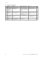
Artigos relacionados
Outros documentos
-
Riello START AQUA CONDENS 25 BIS NG Manual do usuário
-
-
Sorel LHCC S45 24V Manual do proprietário
-
-
-
Calorex I-PAC Guia de instalação
-
Argo AQUA UNIT VERTICALE Installation & User Manual
-
-
Full Gauge Controls ANASOL Manual do proprietário
-
HTW CALDERA BEROA Manual do usuário