Yamaha GX-700VCD Manual do proprietário
- Categoria
- Tocadores de CD
- Tipo
- Manual do proprietário

R T L
STANDBY TIMER
DOWN UP
VOLUME
STANDBY/ON
AUTO REVERSE CASSETTE DECK
DOLBY B NR
PRESET
/
TUNING
/
BAND A
/
B
/
C
/
D
/
E
DISC
1
DISC
2
DISC
3
DISC CHANGE OPEN
/
CLOSE
PROGRAM
B.BOOST
MUSIC
INPUTINPUT
DIRECTION
PUSH OPEN
MINI COMPONENT SYSTEM GX–700
OWNER’S MANUAL
3
–
DISC VCD CHANGER

2
22
● Front speakers
●
● Center speaker
●
● Rear speakers
●
● Speaker cords
●
● AM loop antenna
●
● Indoor FM antenna
●
1
1
2
2
3
3
4
4
5
5
6
6
7
7
8
8
9 0
TIME PROG R. TIME
C
EDIT
D
PRESET
+
I0
E
MODE REPEAT
RANDOM
TUNER
DISC SKIP
DIRECTION
CENTER
/
REAR
/
DELAY
TEST
PROGRAM
BASS
BOOST
MUSIC
POWER
SLEEP
INPUT
VOLUME
AB
TAPE
LEVEL
/I
KEY
/
ECHO
SELECTRETURNTIME INDEX
DIGEST
KARAOKE
INTRO
TUNER
VCD
/
CD
REC
/
PAUSE
DISC
1
DISC
2
DISC
3
3
–
DISC VCD CHANGER
STANDBY TIMER
DOWN UP
VOLUME
STANDBY/ON
AUTO REVERSE CASSETTE DECK
DOLBY B NR
DIRECTION
PROGRAM
B.BOOST
MUSIC
INPUTINPUT
PRESET
/
TUNING
/
BAND A
/
B
/
C
/
D
/
E
DISC CHANGE OPEN
/
CLOSE
MINI COMPONENT SYSTEM GX–700VCD
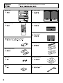
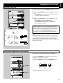
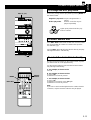
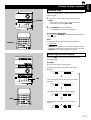
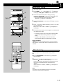
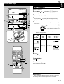
Unpacking ● After unpacking, check that the following parts are contained.
●
● Main unit
●
● Remote control
●
● Batteries (size AA, UM/SUM-3, R6, HP-7)
●
● Mounting brackets
●
● Screws
●
● Pads
●

3
33
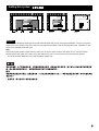
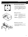
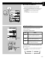
Setting this system
1 cm 1 cm
20 cm20 cm
20 cm
20 cm
20 cm
20 cm 20 cm
20 cm
*
English
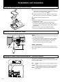
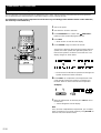
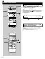
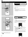
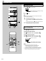
Set this system allowing enough spaces around and behind the main unit to assure good ventilation. Be sure not to place
another unit or any object on top of the main unit to prevent the ventilation holes from being obstructed. Otherwise, it may
cause fire or damage to the main unit.
Note
When placing the speakers apart from the main unit, be sure to allow a space of at least 20 cm (3-15/16”) above,
behind and on both sides of the main unit. If the main unit is put in a rack, the front of it must be fully opened.
*
The values must be applied to China and Singapore models only.

4
44
DISC
1
DISC
2
DISC
3
3
–
DISC VCD CHANGER
STANDBY TIMER
DOWN UP
VOLUME
STANDBY/ON
AUTO REVERSE CASSETTE DECK
DOLBY B NR
DIRECTION
PROGRAM
B.BOOST
MUSIC
INPUTINPUT
PHONES
MIN
PRESET
/
TUNING
/
BAND A
/
B
/
C
/
D
/
E
DISC CHANGE OPEN
/
CLOSE
TREBLEBASS
AUTO/MANUAL
TIMER
MEMORY
TIME ADJ
REC/PAUSEDOLBY NR
HOUR
RANDOM
REPEAT TIME
DISPLAYMODE
MIC MIXING
KARAOKE
MIN
MAX
1 MIC 2
2
3
4
5
6
8
0
B
N
M
L
K
J,
I,
H
G
F
E,
D,
C,
9
A
7
1
a
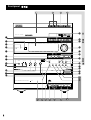
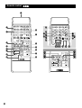
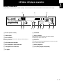
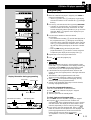
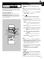
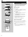
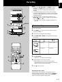
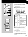
Front panel

5
55
1 Display
2 Remote control sensor
3 TIMER
4 STANDBY [p. 12]
5 B. BOOST [p. 32]
6 PROGRAM [p. 35]
7 KARAOKE [p. 37]
8 PHONES [p. 33]
O Disc tray
[p. 12]
P DISC (1, 2, 3) [p. 13]
Q DISC CHANGE [p. 14]
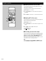
Amplifier/tuner
9 MIC (1, 2) [p. 37]
0 BASS/TREBLE [p. 32]
A MIC MIXING [p. 37]
B Front cover
C / [p. 21, 22]
D A/B/C/D/E [p. 22]
E PRESET/TUNING/BAND
[p. 21]
F VOLUME [p. 32]
G MUSIC [p. 33]
H INPUT( / ) [p. 12, 21, 25, 31]
I HOUR [p. 9, 39]
J MIN [p. 9, 39]
K DISPLAY [p. 9, 39]
L MEMORY [p. 22, 23]
TIME ADJ [p. 9]
M STANDBY/ON
[p. 10]
N AUTO/MANUAL [p. 21]
TIMER [p. 39]
R OPEN/CLOSE [p. 12]
S ( )/ ( )
[p. 14, 19]
T / [p. 12]
U [p. 12]
V RANDOM [p. 17]
W TIME [p. 17]
X REPEAT [p. 16]
Y Tray
[p. 25]
Z MODE [p. 25]
[ [p. 25]
\ DIRECTION [p. 25]
] ( )/ ( ) [p. 26]
` [p. 25]
a [p. 25]
b REC/PAUSE [p. 27]
c DOLBY NR [P. 24, 27]
CD/Video CD player
Tape deck
TUNER → TAPE → VCD/CD
↑
AUX/MD ← VCR ← VIDEO
↑

6
66
1
1
2
2
3
3
4
4
5
5
6
6
7
7
8
8
9 0
TIME PROG R. TIME
C
EDIT
D
PRESET
+
I0
E
MODE REPEAT
RANDOM
TUNER
DISC SKIP
DIRECTION
CENTER
/
REAR
/
DELAY
TEST
PROGRAM
BASS
BOOST
MUSIC
POWER
SLEEP
INPUT
VOLUME
AB
TAPE
LEVEL
/I
KEY
/
ECHO
SELECTRETURNTIME INDEX
DIGEST
KARAOKE
INTRO
TUNER
VCD
/
CD
REC
/
PAUSE
DIRECTION
CENTER
/
REAR
/
DELAY
TEST
PROGRAM
BASS
BOOST
MUSIC
POWER
SLEEP
INPUT
VOLUME
TAPE
LEVEL
/I
KEY
/
ECHO
REC
/
PAUSE
1
1
2
2
3
3
4
4
5
5
6
6
7
7
8
8
9 0
TIME PROG R. TIME
C
EDIT
D
PRESET
+
I0
E
MODE REPEAT
RANDOM
TUNER
DISC SKIP
AB
SELECTRETURNTIME INDEX
DIGEST
KARAOKE
INTRO
TUNER
VCD
/
CD
2
3
4
6
5
8
9
F
E
D
B
A
0
C
1
7
J
H
G
L
M
Y
Z
[
\
X
NOP Q R S
W
I
K
T
U
V
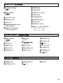
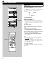
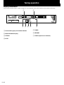
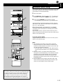
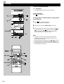
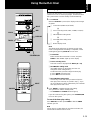
Remote control

7
77
1 Transmission window
[p. 4]
2 Numeric buttons
[p. 22]
3 A, B, C, D, E [p. 22]
4 KARAOKE [p. 37]
5 TEST [p. 10]
6 CENTER/REAR/DELAY [p. 36]
KEY/ECHO [p. 38]
7 LEVEL (–/+) [p. 10, 36, 38]
LEVEL ( / ) [p. 38]
G Numeric buttons
[p. 13]
H TIME [p. 17]
I PROG [p. 15]
J MODE [p. 13]
K REPEAT [p. 16]
8 POWER [p. 10]
9 SLEEP [p. 40]
0 PRESET ( / ) [p. 22]
A TUNER [p. 21]
B PROGRAM [p. 35]
C BASS BOOST [p. 32]
D MUSIC [p. 33]
E VOLUME (+/–) [p. 32]
F INPUT ( / ) [p. 12, 21, 25, 31]
L DISC SKIP
[p. 13]
M ( )/ ( )
[p. 14, 19]
N INTRO [p. 18]
O TIME INDEX [p. 18]
P DIGEST [p. 18]
Q RETURN [p. 19]
R SELECT [p. 19]
S [p. 12]
T EDIT [p. 29, 30]
U R. TIME [p. 29]
V RANDOM [p. 17]
W [p. 12]
X / [p. 26]
Y REC/PAUSE [p. 27]
Amplifier/tuner
CD/Video CD player
Tape deck
Z DIRECTION [p. 25]
[ [p. 25]
\ [p. 25]
TUNER → TAPE → VCD/CD
↑
AUX/MD ← VCR ← VIDEO
↑

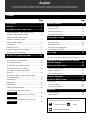
Contents
English
Thank you for purchasing this YAMAHA product. We hope it will give you many years of trouble-free enjoyment.
For the best performance, read this manual carefully. It will guide you in operating your YAMAHA product.
Page
Tuning operation ......................................
20
Automatic tuning ....................................................21
Manual tuning ........................................................21
Manual preset tuning .............................................22
Automatic preset tuning ......................................... 23
Playing back a tape..................................
24
General information ...............................................24
Basic operation ......................................................25
Winding the tape ....................................................26
Searching for the beginning
of the desired selection ..........................................26
Recording .................................................
27
Basic recording ......................................................27
Recording from CDs utilizing the EDIT function..... 29
Operating an external unit connected
with this system .......................................
31
Various sound control .............................
32
General sound control............................................ 32
Graphic equalizer...................................................33
Sound field processor ............................................34
Karaoke operation....................................
37
Using the built-in timer ............................
39
Timer play ..............................................................39
Timer recording......................................................40
Sleep timer operation.............................................40
Appendix...................................................
41
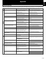
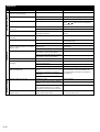
Troubleshooting .....................................................41
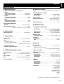
Specifications.........................................................43
Page
Precautions.................................................
1
Features ......................................................
3
Preparations and connections..................
4
Installing batteries in the remote control ..................4
Remote control operation range ..............................4
Setting the video output format
selector (TV MODE) switch......................................4
Setting up the speakers ...........................................5
Connections .............................................................7
Setting the clock.......................................................9
Adjusting brightness of the display ..........................9
Speaker balance adjustment..................................10
CD/Video CD player operation ................
11
Basic play............................................................... 12
To change the disc play mode ...............................13
To select another disc ............................................ 13
To select the desired track directly ......................... 13
To play the desired track (Skip)..............................14
To advance or reverse play rapidly
(Search) .................................................................14
To exchange a disc (or discs) while playing
(PLAYXCHANGE) ..................................................14
Program play..........................................................15
Repeat play ............................................................16
Random play .......................................................... 17
Switching the time display......................................17
To find your desired scence quickly
for Video CDs................................................................. 18
To get a quick overview of a track or a disc
for Video CDs ................................................................ 18
Playback Control of Video CD (version 2.0)
for Video CDs ................................................................ 19
For basic source play, the following illustrations on top of
pages will help you to look for the section you need.
..... CD/Video CD play ..... Tuning
..... Tape playback/recording

E-1
English
■ To assure the finest performance, please read this manual
carefully. Keep it in a safe place for future reference.
■ Choose the installation location of this system carefully.
Avoid placing it in direct sunlight or close to a source of
heat. Also avoid locations subject to vibration and
excessive dust, heat, cold or moisture. Keep it away from
sources of hum such as transformers and electric motors.
■ Do not operate this system upside-down. It may overheat,
possibly causing damage.
■ Never open the cabinet. If something drops into the set,
contact your dealer.
■ The openings on the main unit cover assure proper
ventilation of the main unit. If these openings are
obstructed, the temperature inside the main unit will rise
rapidly. Therefore, avoid placing objects against these
openings, and install the main unit in a well-ventilated area
to prevent fire and damage.
■ Always set the VOLUME control to minimum before
starting an audio source play: increase the volume
gradually to an appropriate level after play has started.
■ When not planning to use this system for long periods of
time (ie., vacation, etc.), disconnect the AC power plug
from the wall outlet.
■ Grounding or polarization – Precautions should be taken so
that the grounding or polarization of this system is not
defeated.
■ Do not use force on switches, controls or connection wires.
When moving the main unit, first disconnect the power plug
and the wires connected to other equipment. Never pull the
wire itself.
■ If an external appliance (TV, radio, etc.) interferes with this
system operation, move the main unit away from such an
appliance.
■ Do not attempt to clean this system with chemical solvents;
this might damage the finish. Use a clean, dry cloth.
■ Be sure to read the “Troubleshooting” section regarding
common operating errors before concluding that this
system is faulty.
■ To prevent lightning damage, disconnect the AC power
plug and the antenna cable when there is an electrical
storm.
■ Do not plug the AC power plug to the wall socket before
you finish all connections.
■ Never allow metallic items (e.g. screwdrivers, tools, etc.) to
come near the tape deck’s record/playback head assembly.
Doing so may not only scratch or damage the head’s
mirror-smooth finish, it may change the magnetic
characteristics of the heads, causing a deterioration in
reproduction performance quality.
■ Although the tape deck’s record/playback heads are high
quality heads with outstanding reproduction characteristics,
they can become dirty through the use of old tapes or from
dust accumulation over time. This can have a serious effect
on reproduction quality. Clean the heads regularly with one
of the commonly available head cleaners or with cleaning
solutions.
■ The voltage to be used must be the same as that specified
on this system. Using this system with a higher voltage
than specified is dangerous and may result in a fire or other
types of accidents causing damage. YAMAHA will not be
held responsible for any damage resulting from use of this
system with a voltage other than specified.
■ The sound level at a given volume setting depends on
speaker location and other factors. Care should be taken to
avoid exposure to sudden high levels of sound, which may
occur when turning on this system with the volume control
setting at high, and to continuous high levels of sound.
■ Sudden temperature changes and storage or operation in
an extremely humid environment may cause condensation
inside the cabinet. Condensation can cause this system to
malfunction.
To eliminate condensation:
•
Pickup
Leave the power on with no disc loaded until normal
play becomes possible (about 1 hour).
•
Tape head
Leave the power on with no tape loaded until normal
playback becomes possible (about 1 hour).
Note
If condensation forms on the tape head, dirt or dust
may accumulate during use.
•
Remote control
Wipe off condensation on the transmission window with
a soft cloth before operating this system.
■ To prevent a malfunction of this system:
•
Do not use any non standard shaped disc (heart etc.)
available on the market, because it may damage this
system.
•
Do not use a disc with tape, seals, or paste on it,
because damage to this system may result.
Precautions: Read this before operating your system
IMPORTANT
Please record the serial number of this system in the space
below.
Model:
Serial No.:
The serial number is located on the rear of the main unit.
Retain this Owner’s Manual in a safe place for future
reference.
WARNING
TO REDUCE THE RISK OF FIRE OR ELECTRIC SHOCK,
DO NOT EXPOSE THIS APPLIANCE TO RAIN OR
MOISTURE.

E-2
Precautions: Read this before operating your system
WARNING
To reduce the risk of fire or electric shock, do not expose this
system to rain or moisture.
To avoid electrical shock, do not open the cabinet. Refer
servicing to qualified personnel only.
CAUTION
Use of controls or adjustments or performance of
procedures other than those specified herein may result in
hazardous radiation exposure.
As the laser beam used in this unit is harmful to the eyes, do
not attempt to disassemble the cabinet. Refer servicing to
qualified personnel only.
This system is classified as a
CLASS 1 LASER product.
The CLASS 1 LASER
PRODUCT label is located on
the rear exterior.
CLASS 1 LASER PRODUCT
Laser component in this product is capable of emitting
radiation exceeding the limit for Class 1.
CAUTION FOR CARRYING THE MAIN UNIT
Be sure not to carry or tip the main unit with discs
remaining in it.
CAUTION FOR MOVING THE MAIN UNIT
Before moving the main unit, first remove all discs from the
disc tray and close the tray by pressing the OPEN/CLOSE
button. After you confirm that “NO DISC” lights up on the
display, turn this system into the standby mode by pressing
the STANDBY/ON switch, and then disconnect the power
plug from the AC outlet.
Voltage Selector (China and General models only)
The voltage selector on the rear panel of the main unit
must be set for your local main voltage BEFORE
plugging into the AC main supply.
Voltages are 110/120/220/240 V AC, 50/60 Hz.
FREQUENCY STEP switch
(China and General models only)
Because the interstation frequency spacing differs in
different areas, set the FREQUENCY STEP switch (located
at the rear) according to the frequency spacing in your
area.
Be sure to change the setting of this switch with the AC
supply lead of this system disconnected from the AC outlet.
This system is not disconnected from the AC power
source as long as it is connected to the wall outlet, even if
this system itself is turned off. This state is called the
standby mode.
In this state, this system is designed to consume a certain
level of power.
Note
Please check the copyright laws in your country to record
from records, compact discs, radio, etc. Recording of
copyright material may infringe copyright laws.
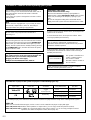
The CD/Video CD player in this system can play discs of the following types only.
Never attempt to play a disc other than above with the CD/Video CD player because it may cause a damage to this system.
VIDEO CD
Video CDs are classified into two types, version 1.1 and 2.0. The CD/Video CD player can play both types.
Video CD (version 1.1): With the same operation as compact discs, you can enjoy sounds and pictures (movies).
Video CD (version 2.0): In addition to a normal play which is the same as version 1.1, you can enjoy a Playback Control
operation. (For details on Playback Control, refer to page 19.)
Type of disc
Video CD
CD
Mark printed
on the disc
Type of signal
recorded
Sound
+
Picture (Movie)
Size (Dimension)
12 cm
8 cm (Single type)
12 cm
8 cm (Single type)
Maximum possible
play time
74 minutes
20 minutes
74 minutes
20 minutes
Sound only

E-3
English
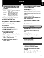
CD/Video CD Player
● 3-Disc Carousel Auto-Changer for Video
CDs and Compact Discs
● PLAYXCHANGE
Disc changing while playing
● 20-Track Random Access Programming
● Repeat Play for Single Track/Entire Disc/
All Discs
● Random Sequence Play
● Playback Control Function Available for
Video CD (version 2.0)
● Quick Overview of a Track and a Disc
with a Touch of the DIGEST and INTRO
Buttons
● Time Index Function
Tape Deck
● Automatic Synchronized Recording with
CD or Video CD
● EDIT Function Useful for Recording
CD(s)
●
Automatic Reverse
●
Dolby B Type Noise Reduction System
Tuner
●
40 Station Preset Tuning
●
Automatic Preset Tuning
Karaoke-functions
●
4 Modes for Singing Karaoke
●
2 Microphone Connecting Capability
●
Mic Mixing, Echo Level and Key Control
Capability
●
Karaoke Sound Recording Capability
(Recording Your Singing Voice and Karaoke
Effects with the Music Source)
Features
General
●
5-Speaker Multichannel Audio System
(Two front, One Center and Two Rear
Speakers)
●
High Power Output
Front L, R: 100W + 100W (6Ω) RMS, 10%
THD, 1 kHz
Center: 100W (6Ω) RMS Output
Power, 10% THD, 1 kHz
Rear: 30W (6Ω) RMS Output
Power, 10% THD, 1 kHz
● 4 External Audio/Video Component
Connecting Capability
● Multiuse Timer/Sleep Timer
● SUBWOOFER Output for Low Frequency
Expansion
● Remote Control Capability
● BASS BOOST
● 5-Band Spectrum Analyzer
● DOLBY PRO LOGIC and DOLBY 3
STEREO Decoding
● Sound Field Processing
(HALL and YMERSION)
● Test Tone Generator for Easier Speaker
Balance Adjustment
● 3 Preset Graphic Equalizer Modes
(ROCK, POPS and JAZZ)
● Video Output Format Selector (TV
MODE) Switch

E-4
Preparations and connections
Installing batteries in the remote control
Notes
● The area between the remote control and the main unit must
be clear of large obstacles.
● Do not expose the remote control sensor to strong lighting,
in particular, an inverter type fluorescent lamp. Otherwise,
the remote control may not work properly. If necessary,
position the main unit away from direct lighting.
Battery replacement
If you find that the remote control must be used closer to the
main unit, the batteries are weak. Replace both batteries with
new ones.
Remote control operation range
2
1
3
SET MD
REC/PAUSE
TAPE
DISC
1
DISC
2
DISC
3
3
–
DISC VCD CHANGER
DOWN UP
VOLUME
PUSH OPEN
MINI COMPONENT SYSTEM GX–700
MINIDISC RECORDER
MD
PRESET
/
TUNING
/
BAND A
/
B
/
C
/
D
/
E
DISC CHANGE OPEN
/
CLOSE
MODE
–
PTY SEEK
–
START
30°
30°
Setting the video output format selector (TV MODE) switch
This system is designed for use with the NTSC and PAL
television formats. Set this switch to the position for the format
your TV monitor employs.
PAL: Set to this position if your TV monitor employs the PAL
format.
AUTO: Set to this position if your TV monitor can be switched
in between the PAL and NTSC formats automatically.
NTSC: Set to this position if your TV monitor employs the
NTSC format.
1. Turn the remote control over and remove the battery
compartment cover by pulling it up while pressing the edge
of the cover in the direction of the mark.
2. Insert the batteries (AA, R6, UM-3 type) according to the
polarity markings on the inside of the battery compartment.
3. Attach the battery compartment cover.
Notes
● Remove the batteries if the remote control is not used for an
extended period of time.
● If batteries leak, dispose of them immediately. Avoid
touching the leaked material and contact with clothing, etc.
Clean the battery compartment thoroughly before installing
new batteries.
● Be sure to use the same type of batteries together.
● Do not use a new battery and an old battery together.
ANTENNA
75
Ω
UNBAL.
FM GND AM
DIGITAL OUT
OPTICAL
OUT
RL
VIDEO SIGNAL
MONITOR
OUT
OUT
VCR
SUBWOOFER
TV MODE
PAL
NTSC
AUTO
SPEAKERS
SEE OWNER’S MANUAL
FOR CONNECTION.
CENTER: 6
Ω
MIN./SPEAKER
REAR: I2
Ω
MIN./SPEAKER
CENTERREAR REAR
R L
TV MODE
PA L
NTSC
AUTO
(Singapore model)
0.2 m – 6 m
(8” – 20’)

E-5
English
Front L Center Front R
DialogueDialogo
Rear L Rear R
Setting up the speakers
m 4 channel 5 speaker configuration
This system employs a 5 speaker configuration: 2 front
speakers, 2 rear paralleled speakers and a center speaker.
The front speakers are used for outputting main source sound.
The rear speakers are for effect and surround sounds when
the sound field program
PRO LOGIC or HALL is selected.
The center speaker is for center sounds (dialog etc.) when the
sound field program PRO LOGIC or 3 STEREO is
selected.
m Placing the speakers
Front speakers: On both sides of the TV and almost the
same height as the TV.
Center speaker: Precisely between the front speakers.
Rear speakers: Behind your listening position, facing
slightly inward. Nearly 1.8 m (approx. six
feet) up from the floor.
Subwoofer: The position of the subwoofer is not so
(separate purchase)
critical because low bass tones are not
highly directional.
m Mounting the center speaker
Place the center speaker on the TV, on the floor under the TV
or in the TV rack so that it is stabilized.
When placing the speaker on top of the TV, to prevent the
speaker from falling down, put the provided pads at four points
on bottom of the speaker.
Preparations and connections
Front L
Center
Front R
Subwoofer
Rear L
Rear R
TV set

E-6
Preparations and connections
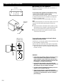
m Mounting the rear speakers
Mount the rear speakers on a shelf, rack or on the floor, or
hang them on the wall.
To mount the rear speakers on the wall by using
commercially available speaker stands
The provided mounting bracket has 1 pair of screw holes (at
an interval of 60 mm). They are available for mounting the
speaker on a speaker stand.
* Those screw holes can be used with M4 screws only.
Note
It is recommended that you connect the speaker cords to the
speaker’s terminals before attaching the bracket to the
speaker.
1 Attach the bracket to the bottom of the speaker by using
the provided screw so that the convex part of the bracket
fits in the grooved part of the speaker as figured left.
2 Mount the speaker on the speaker stand by using the
screw holes on the bracket.
To mount the rear speakers on the wall without
using any bracket or stand
If desired, you can hang the speaker on the protruding screws
on the wall without using the bracket.
Fasten screws into a firm wall or wall support as figured left,
and hang the holes of the speaker on the protruding screws.
* Make sure that the screws are caught by a narrow part of
the holes securely.
WARNING:
● Each of the rear speakers weighs 0.8 kg (1 lbs. 12 oz.).
Do not mount them on thin plywood or soft wall
surface material, as the screws may come out of the
flimsy surface, causing the speakers to fall down and
be damaged, or result in personal injury.
● Do not fasten the speakers to the wall with nails,
adhesives, or other unsound hardware. Long-term use
and vibrations may cause them to fall down.
● To avoid accidents resulting from tripping over loose
speaker cords, fix them to the wall.
● Select a proper position on the wall to mount the
speaker and the stand so that no one will hit his head
or forehead on the projections of them, resulting in
personal injury.
60 mm
Mounting
bracket
Screw
Tapping screw
(Available at the
hardware store)
Min.
12 mm
65 mm
Wall or wall
support

E-7
English
MAINS
RL
OUT
IN
AUX/MD
VIDEO SIGNAL
MONITOR
OUT
OUT
VCR
IN
VIDEO
OUT
SUBWOOFER
TV MODE
PA L
NTSC
AUTO
SPEAKERS
SEE OWNER’S MANUAL
FOR CONNECTION.
SPEAKERS
CENTER: 6
Ω
MIN./SPEAKER
REAR: I 2
Ω
MIN./SPEAKER
CENTERREAR REAR
R L
6
Ω
MIN./SPEAKER
FRONT
R L
R
L
L R
Preparations and connections
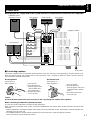
Never plug the AC supply lead of this system into the AC outlet until all connections are completed.
Connections
Caution
Do not let the bare speaker wires touch each other as this could damage the amplifier and/or speakers.
When connecting a subwoofer (separate purchase)
You may wish to add a subwoofer to reinforce the bass frequencies.
When connecting a subwoofer to this system, connect the SUBWOOFER OUT terminal of this system to the INPUT terminal of the
subwoofer.
* Ordinary subwoofers, including the Yamaha Active Servo Processing Subwoofer System, are designed so that the amplifier and
subwoofer are in the same unit.
* The SUBWOOFER OUT terminal outputs low frequencies from the left front, center and right front channels.
(The cut-off frequency of this terminal is 200 Hz.)
m Connecting speakers
Connect the speakers to the corresponding speaker terminals on the rear of the main unit respectively by using the speaker cords.
Make sure that the polarity of the speaker cords is correct, that is the + and – markings are observed. If these cords are reversed,
the sound will be unnatural and lack bass.
On the main unit
Red: positive (+)
Black: negative (–)
1 Press up the tab.
2 Insert the bare wire.
[Remove approx. 5mm (1/4”)
insulation from the speaker
wires.]
3 Press down the tab and
secure the wire.
1
2
3
On the speakers
Red: positive (+)
Black: negative (–) 1 Press the tab
2 Insert the bare wire.
[Remove approx. 5mm
(1/4”) insulation from
the speaker wires.]
3 Release the tab and
secure the wire.
INPUT
Subwoofer system
(Separate purchase)
Rear speaker
1
2
3
Front speakers
Rear speaker
Center speaker
To AC outlet
(Singapore model)

E-8
DIGITAL OUT
OPTICAL
RL
OUT
IN
AUX/MD
VIDEO SIGNAL
MONITOR
OUT
OUT
VCR
IN
VIDEO
OUT
SUBWOOFER
TV MODE
PAL
NTSC
AUTO
SPEAKERS
SEE OWNER’S
M
FOR CONNECTI
O
CENTER: 6
Ω
MIN./
S
REAR: I 2
Ω
MIN./
S
CENTERREAR
R
FRONT
R
L
Preparations and connections
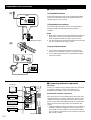
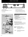
m Connecting external components
TV monitor
Connect a TV monitor to enjoy playing Video CDs on the built-
in CD/Video CD player. Connect a TV monitor to the
MONITOR OUT terminal using an RCA pin plug cable.
External audio and video components
This system can be connected with external audio and video
components. Make connections between this system and the
components using RCA pin plug connector cables correctly,
that is to say L (left) to L and R (right) to R. Also, refer to the
owner’s manual for the component to be connected to this
system.
* A digital-to-digital recording is possible from a CD played on
the built-in CD/Video CD player to an MD (or tape) on an
external MD recorder (or DAT) by connecting the DIGITAL
OUT (OPTICAL) terminal on the rear of the main unit to the
MD recorder (or DAT).
m Antenna connection
(1) Supplied FM antenna
Connect the FM antenna wire to the corresponding terminal
and direct the FM antenna wire to the direction where the
strongest signal can be received.
(2) Supplied AM loop antenna
Connect the AM loop antenna wires to the corresponding
terminals. Position the AM loop antenna for optimum
reception.
Notes
● When static is still heard even after adjusting the position of
the AM loop antenna, try reversing the wire connections
(from the right terminal to the left one, and vice versa).
● The AM loop antenna should be placed apart from the main
unit. The antenna may be hung on a wall.
Using an external antenna
● Use an external FM antenna instead of an indoor FM
antenna if you need better reception. Consult your dealer.
● Use an external AM antenna if you need better reception.
Consult your dealer.
(1)
(2)
ANTENNA
75Ω UNBAL.
FM GND AM
ANTENNA
75Ω UNBAL.
FM GND AM
DIGITAL OUT
OPTICAL
ANTENNA
75Ω UNBAL.
FM GND AM
TV monitor
VCR
LD/DVD player, etc.
MD recorder, etc.
(Singapore model)
(Singapore model)

E-9
English
DISC
1
DISC
2
DISC
3
DOWN UP
VOLUME
STANDBY/ON
PROGRAM
B.BOOST
MUSIC
INPUTINPUT
MIN
PRESET
/
TUNING
/
BAND A
/
B
/
C
/
D
/
E
DISC CHANGE OPEN
/
CLOSE
AUTO/MANUAL
TIMER
MEMORY
TIME ADJ
REC/PAUSEDOLBY NR
HOUR
RANDOM
REPEAT TIME
DISPLAYMODE
KARAOKE
DISC
1
DISC
2
DISC
3
STANDBY TIMER
DOWN UP
VOLUME
STANDBY/ON
AUTO REVERSE CASSETTE DECK
DOLBY B NR
DIRECTION
PROGRAM
B.BOOST
MUSIC
INPUTINPUT
PHONES
MIN
PRESET
/
TUNING
/
BAND A
/
B
/
C
/
D
/
E
DISC CHANGE OPEN
/
CLOSE
BASS
AUTO/MANUAL
TIMER
MEMORY
TIME ADJ
REC/PAUSEDOLBY NR
HOUR
RANDOM
REPEAT TIME
DISPLAYMODE
TREBLE MIC MIXING
MIN
MAX
1 MIC 2
KARAOKE
1
2
3
RANDOM
REPEAT
HOUR
MIN
DISPLAY
MEMORY
TIME ADJ
MEMORY
TIME ADJ
RANDOM
REPEAT
HOUR
MIN
3
–
DISC VCD CHANGER
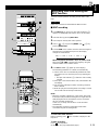
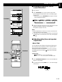
1 While the power is on, press DISPLAY to display the time.
2 While holding TIME ADJ pressed, press HOUR and set the
hour.
* Press HOUR once to advance the time by 1hour. Press
and hold to advance continuously.
3 While holding TIME ADJ pressed, press MIN and set the
minute.
* Press MIN once to advance the time by 1
minute. Press and hold to advance continuously.
* The hour setting will not advance even if minute is
advanced from “59” to “00”.
Singapore model uses a 24-hour display. For China and
General models, either the 24-hour display or the 12-hour
display [shown by “AM (PM) 12:00”] is selected depending
on the setting of the FREQUENCY STEP switch on the
rear panel, so you cannot select the desired type freely.
Note
In the event of a power failure or when the AC supply lead is
disconnected, the time display will go out, however, the clock
will function for about 5 minutes without any power supply.
Otherwise, the time display will flash on and off to indicate that
the time must be reset.
If desired, you can adjust the brightness of the display.
Press and hold DISPLAY for more than 2 seconds so that
“DIMMER ±0” appears on the display.
While holding DISPLAY pressed, turn VOLUME clockwise to
increase or counterclockwise to decrease brightness.
Control range: ±0 to –6 (Preset value: ±0)
Setting the clock
Adjusting brightness of the display
Changes.
Changes.
Preparations and connections
VOLUME
DISPLAY

E-10
PROGRAMMUSIC
TEST
CD
PRO LOGIC
Preparations and connections
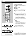
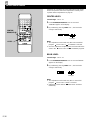
1 Turn on the power.
2 Turn down the volume to minimum.
3 Press PROGRAM once or more until “ PRO LOGIC”
lights up on the sound field program indicator.
4 Press TEST.
* “TEST” flashes on and off on the display.
5 Press VOLUME + (up) to increase the volume.
You will hear a test tone (like pink noise) from the left front
speaker, the center speaker, the right front speaker, and
then the rear speakers, for about 2.5 seconds each. The
display changes as shown below.
* The test tone from the left rear speaker and the right rear
speaker will be heard at the same time.
6 Press LEVEL +/– to adjust the sound output levels of the
center speaker and the rear speakers so that the level
becomes almost as same as that of the front speakers.
example)
7 When the adjustments are finished, press TEST to cancel
the test tone.
* “TEST” disappears from the display.
Note
Once you have completed these adjustments, you can adjust
whole sound level on your audio system by using VOLUME on
the main unit (or the remote control).
Speaker balance adjustment
You can adjust the sound output level balance between the front, center, and rear speakers using the built-in test tone generator.
This is important for the best performance of the built-in Dolby Pro Logic surround decoder.
The adjustment of each speaker output level should be done at your listening position with the remote control. Otherwise,
the result may not be satisfactory.
Changes.
1
1
2
2
3
3
4
4
5
5
6
6
7
7
8
8
9 0
TIME PROG R. TIME
C
EDIT
D
PRESET
+
I0
E
MODE REPEAT
RANDOM
TUNER
DISC SKIP
DIRECTION
CENTER
/
REAR
/
DELAY
TEST
PROGRAM
BASS
BOOST
MUSIC
POWER
SLEEP
INPUT
VOLUME
AB
TAPE
LEVEL
/I
KEY
/
ECHO
SELECTRETURNTIME INDEX
DIGEST
KARAOKE
INTRO
TUNER
VCD
/
CD
REC
/
PAUSE
3
2, 5
4, 7
6
1

E-11
English
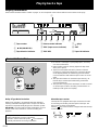
CD/Video CD player operation
1 TRACK (track number)
2 Time display
3 Disc indicator
The disc of the number located on the top of this indicator is
now being selected.
4 VCD (Video CD) indicator
5 PBC (Playback Control) indicator
6 CD (input source indicator)
7 (play)
Display information
8
RANDOM
9 Music calendar
Track numbers on the currently selected disc will be
illuminated (up to the number 15).
0 OVER 15
This indicator will be illuminated when the currently selected
disc has more than 15 tracks.
A PROG (program)
B (S, F) REP [(single, full) repeat]
Each indicator mentioned with a number on pages 12–19 corresponds to the indicator with the same number on this page.
100 350 1K 3.5K 10K
MUSIC
PROG
S F REP
VOLUME
OVER 15
1234
78910
13 14 15
5
11
6
12
TOTAL REM
TRACK
VCD PBC
RANDOM
CD
PROGRAM
312
0
B
76549
A
8

E-12
1
1
2
2
3
3
4
4
5
5
6
6
7
7
8
8
9 0
TIME PROG R. TIME
C
EDIT
D
PRESET
+
I0
E
MODE REPEAT
RANDOM
TUNER
DISC SKIP
DIRECTION
CENTER
/
REAR
/
DELAY
TEST
PROGRAM
BASS
BOOST
MUSIC
POWER
SLEEP
INPUT
VOLUME
AB
TAPE
LEVEL
/I
KEY
/
ECHO
SELECTRETURNTIME INDEX
DIGEST
KARAOKE
INTRO
TUNER
VCD
/
CD
REC
/
PAUSE
DISC
1
DISC
2
DISC
3
3
–
DISC VCD CHANGER
STANDBY TIMER
DOWN UP
VOLUME
STANDBY/ON
AUTO REVERSE CASSETTE DECK
DOLBY B NR
DIRECTION
PROGRAM
B.BOOST
MUSIC
INPUTINPUT
PHONES
MIN
PRESET
/
TUNING
/
BAND A
/
B
/
C
/
D
/
E
DISC CHANGE OPEN
/
CLOSE
TREBLEBASS
AUTO/MANUAL
TIMER
MEMORY
TIME ADJ
REC/PAUSEDOLBY NR
HOUR
RANDOM
REPEAT TIME
DISPLAYMODE
MIC MIXING
KARAOKE
MIN
MAX
1 MIC 2
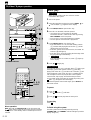
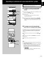
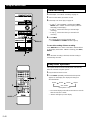
Basic play
*
When you play a Video CD, turn on the TV monitor
connected to this system.
1 Turn on the power.
2 Select the CD/Video CD player by pressing INPUT or
until “VCD/CD” (2) appears on the display.
3 Press OPEN/CLOSE to open the disc tray.
4 Place discs on the table, label side upward.
* Up to three discs can be loaded on the table.
To load the third disc, rotate the disc table by pressing
DISC CHANGE on the front panel.
* 8 cm (3”) discs can be played without an adaptor.
* The disc placed on the left side is played first.
5 Press OPEN/CLOSE to close the disc tray.
* If the selected disc is a CD, the total number of tracks
(1) and the total playing time of the disc (2) will be
displayed for several seconds.
* If the disc contains more than 15 tracks, the “OVER 15”
indicator (
0) will light up.
* If the disc tray is closed by pushing the front edge of the
tray, play will begin automatically.
*
If the selected disc is a Video CD, “VCD” (
4) lights up
on the display.
6 Press / to begin play.
If a Video CD (version 2.0) is selected, “PBC” (
5) lights up on
the display, yet the total number of tracks (
1), the total
playing time of the disc (
2) and the music calendar (9) will
not be displayed. In this mode, disc play is controlled by the
rule of Playback Control. To play the disc in the Playback
Control mode, skip to page 19 and follow the procedure.
To cancel this mode and restore the normal play mode, press
. “PBC” (5) disappears from the display.
To call the Playback Control mode again, press SELECT on
the remote control.
To pause
11 Press / .
* The “
” indicator (7) will flash.
22 Press / to resume play from the same point.
To stop play
Press .
To finish using this system
Turn this system into the standby mode by pressing
STANDBY/ON. (The STANDBY indicator will light up and the
display will go out.)
3, 5
CD/Video CD player operation
2
1
2
4
1
6, 11, 22
4
STANDBY indicator
6, 11, 22
Direct operation
DISC (1, 2 or 3) and OPEN/CLOSE on the front panel and
on the remote control will work if they are pressed when
this system is in the standby mode or another input source is
selected.
SELECT
For Video CDs
For Video CDs
Note for Video CDs
A página está carregando ...
A página está carregando ...
A página está carregando ...
A página está carregando ...
A página está carregando ...
A página está carregando ...
A página está carregando ...
A página está carregando ...
A página está carregando ...
A página está carregando ...
A página está carregando ...
A página está carregando ...
A página está carregando ...
A página está carregando ...
A página está carregando ...
A página está carregando ...
A página está carregando ...
A página está carregando ...
A página está carregando ...
A página está carregando ...
A página está carregando ...
A página está carregando ...
A página está carregando ...
A página está carregando ...
A página está carregando ...
A página está carregando ...
A página está carregando ...
A página está carregando ...
A página está carregando ...
A página está carregando ...
A página está carregando ...
A página está carregando ...
-
 1
1
-
 2
2
-
 3
3
-
 4
4
-
 5
5
-
 6
6
-
 7
7
-
 8
8
-
 9
9
-
 10
10
-
 11
11
-
 12
12
-
 13
13
-
 14
14
-
 15
15
-
 16
16
-
 17
17
-
 18
18
-
 19
19
-
 20
20
-
 21
21
-
 22
22
-
 23
23
-
 24
24
-
 25
25
-
 26
26
-
 27
27
-
 28
28
-
 29
29
-
 30
30
-
 31
31
-
 32
32
-
 33
33
-
 34
34
-
 35
35
-
 36
36
-
 37
37
-
 38
38
-
 39
39
-
 40
40
-
 41
41
-
 42
42
-
 43
43
-
 44
44
-
 45
45
-
 46
46
-
 47
47
-
 48
48
-
 49
49
-
 50
50
-
 51
51
-
 52
52


Yamaha GX-700VCD Manual do proprietário
- Categoria
- Tocadores de CD
- Tipo
- Manual do proprietário
em outros idiomas
- español: Yamaha GX-700VCD El manual del propietario
- français: Yamaha GX-700VCD Le manuel du propriétaire
- italiano: Yamaha GX-700VCD Manuale del proprietario
- English: Yamaha GX-700VCD Owner's manual
- русский: Yamaha GX-700VCD Инструкция по применению
- Nederlands: Yamaha GX-700VCD de handleiding
- Deutsch: Yamaha GX-700VCD Bedienungsanleitung
- dansk: Yamaha GX-700VCD Brugervejledning
- čeština: Yamaha GX-700VCD Návod k obsluze
- svenska: Yamaha GX-700VCD Bruksanvisning
- polski: Yamaha GX-700VCD Instrukcja obsługi
- Türkçe: Yamaha GX-700VCD El kitabı
- suomi: Yamaha GX-700VCD Omistajan opas
- română: Yamaha GX-700VCD Manualul proprietarului
Artigos relacionados
-
Yamaha GX-500VCD Manual do usuário
-
-
-
-
-
-
-
-
-