
www.regalo-baby.com
Regalo International, LLC.
3200 Corporate Center Drive, Suite 100 / Burnsville, MN 55306, USA
866.272.5274 (U.S. only) or 952.435.1080
Made in China
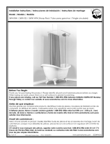
• READ ALL INSTRUCTIONS BEFORE ASSEMBLY AND USE OF GATE.
• KEEP INSTRUCTIONS FOR FUTURE USE.
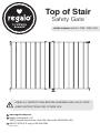
Top of Stair
Safety Gate
OWNER’S MANUAL MODELS: 1230, 1235, 1240

English2
Before Using Product
Read and follow all instructions carefully to ensure that your gate is properly
installed. Improper installation could result in the gate becoming unstable or
dislodged from the doorway. The safety of your child is your responsibility.
Please keep these instructions for your reference.
IMPORTANT
• If hardware mounting to a surface other than drywall or wood, please
consult with a professional about installation.
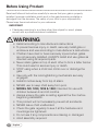
WARNING
• Install according to manufacturer’s instructions
• To prevent serious injury or death, securely install gate or
enclosure and use according to manufacturer's instructions.
• Children have died or been seriously injured when gates
are not securely installed. ALWAYS install and use gates as
directed using all required parts.
• Never stack gates on top of each other to form a taller barrier.
This could result in serious injury or death.
• STOP using when a child can climb over or dislodge the
gate.
• Use only with the locking/latching mechanism securely
engaged.
• Install 6 inches away from top of stairs.
• NEVER use to keep child away from pool.
• MODEL NO. 1230, 1235 & 1240: Intended for use with
children between 6 and 24 months.
• Always ensure the gate is resting against the floor before
beginning installation.
• This product will not necessarily prevent all accidents.
• NEVER leave child unattended.
• Check the gate regularly to see if all the hardware and
mountings are tightened.
• Do not use if any components are missing or damaged.
• Adult assembly required.

English 3
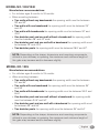
MODEL NO. 1230/1240
Manufacturer recommendations:
• For children ages 6 months to 24 months
• When mounting between:
• Two walls without any baseboards the opening width must be between
28" and 42".
• Two walls with one baseboard the opening width must be between 29"
and 43".
• Two walls with baseboards the opening width must be between 30" and
43.5".
• One banister post and one wall without a baseboard the opening width
must be between 28" and 42" wide.
• One banister post and one wall with a baseboard the opening width must
be between 29" and 42.5".
• Two banister posts the opening width must be between 28.5" and 42".
MODEL NO. 1235
Manufacturer recommendations:
• For children ages 6 months to 24 months
• When mounting between:
• Two walls without any baseboards the opening width must be between
34" and 54".
• Two walls with one baseboard the opening width must be between 35"
and 55".
• Two walls with baseboards the opening width must be between 36.5" and
55.5".
• One banister post and one wall without a baseboard the opening width
must be between 34.5" and 54".
• One banister post and one wall with a baseboard the opening width must
be between 36" and 55".
• Two banister posts the opening width must be between 35" and 54".
NOTE: Depending on the shape, dimensions and mounting components
utilized in your doorway or opening, the maximum and minimum length of
this gate may increase and/or decrease slightly.
NOTE: Depending on the shape, dimensions and mounting components
utilized in your doorway or opening, the maximum and minimum length of
this gate may increase and/or decrease slightly.

English4
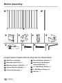
Before Assembly
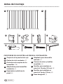
PLEASE CHECK TO MAKE SURE YOU HAVE THE FOLLOWING PARTS:
A Gate Door Assembly
B Mounted Level Poles (2)
C Banister Corner Protectors (16)
D Square Banister Adapters (4)
E Plastic Wall Spacers (6)
F Round Banister Adapter (1)
G Hook and Loop Straps &
Attached Buckles (4)
H 1.5" Wall Mount Screws (6)
I 3" Wall Mount Screws (6)
J Hex Key (1)
D
G
C
A B
E
H I
F
J

English 5
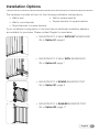
Installation Options
• MOUNTING TO A WALL WITHOUT BASEBOARD
Go to Option A1, page 6
• MOUNTING TO A ROUND BANISTER POST
Go to Option B1, page 9
• MOUNTING TO A WALL WITH BASEBOARD
Go to Option A2, page 7
The hardware included will work for the following installation configurations:
• Wall to wall
• Wall to round banister
• Round banister to square banister
If your installation configuration is not listed above additional installation adapters
are available for purchase. Please contact Regalo for assistance.
• MOUNTING TO A SQUARE BANISTER POST
Go to Option B2, page 11
• Wall to square banister
• Square banister to square banister

English6
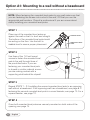
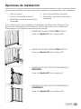
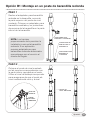
Option A1: Mounting to a wall without a baseboard
STEP 1
Place one of the mounted level poles up
against the wall so that it is level and straight.
The bottom of the mounted level pole should
be resting on the floor. Use the built in
bubble level to ensure proper placement.
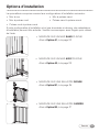
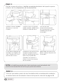
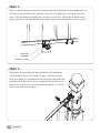
STEP 3
Repeat STEPS 1 – 2 if installing the second mounted level pole to an opposing
wall without a baseboard. If the opposing wall has a baseboard, see page 8. If
fastening the second mounted level pole to a round banister, see page 10. For a
square banister, see page 12.
STEP 4
Once both mounted level poles are securely mounted on both sides of the
opening, see page 14.
STEP 2
Use three of the 1.5" wall mount
screws to fasten the mounted level
pole to the wall through three of
the pre-drilled holes. If you are
fastening your mounted level pole
to drywall or similar material, ensure
you are making contact with a
supporting stud behind the drywall.
NOTE: When fastening the mounted level poles to your wall make sure that
you are fastening the screws into a stud in the wall, OR that you use the
appropriate wall anchors. Consult a professional if you are unsure about
safely installing your mounted level poles.
BUBBLE LEVEL
STUD
DRYWALL
MOUNTED LEVEL
POLE

English 7
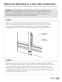
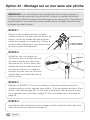
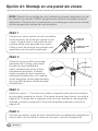
Option A2: Mounting to a wall with a baseboard
NOTE: When fastening the mounted level poles to your wall make sure
that you are fastening the screws into a stud in the wall, OR that you use
the appropriate wall anchors. Consult a professional if you are unsure
about safely mounting your mounted level poles.
STEP 1
Take one of the plastic wall spacers and place it against the wall just
above the baseboard where you want the gate to be positioned. Place
the mounted level pole within the groove of the plastic wall spacer,
making sure the bottom of the mounted level pole is resting on the floor.
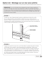
STEP 2
Align the bottom pre-drilled screw hole in the mounted level pole with the
hole in the plastic wall spacer. Use one of the 3" wall mount screws to fasten
the mounted level pole and the plastic wall spacer to the wall. If you are
fastening your mounted level pole to drywall or similar material, ensure you
are making contact with a supporting stud behind the drywall. Do not fully
tighten the wall mount screw yet.
PLASTIC WALL
SPACER
MOUNTED
LEVEL POLE

English8
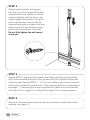
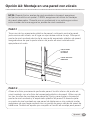
STEP 3
Slide a second plastic wall spacer
from the top of the mounted level pole
downward until the middle pre-drilled
screw hole aligns with the hole in the
second plastic wall spacer. Using the
built in bubble level, ensure that the
mounted level pole is straight and level
before using a 3" wall mount screw to
fasten both components to the wall.
Do not fully tighten the wall mount
screw yet.
STEP 5
Once both mounted level poles are securely mounted on both sides of the
opening, see page 14.
STEP 4
Repeat STEP 3, aligning a third plastic wall spacer with the top pre-drilled
hole in the mounted level pole. Now, go back and fully tighten all three wall
mount screws. Repeat STEPS 1 – 4 if you are installing the second mounted
level pole to a wall with a baseboard. If the opposing wall has no baseboard,
see page 7. If fastening the second mounted level pole to a round banister,
see Option B1 on page 10 or Option B2 on page 12 for a square banister.

BUBBLE
LEVEL
MOUNTED
LEVEL POLE
English 9
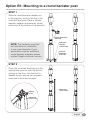
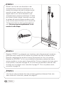
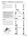
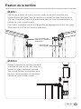
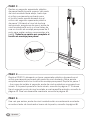
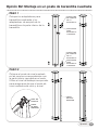
Option B1: Mounting to a round banister post
STEP 1
Slide the round banister adapter on
to the banister, close to the top of the
mounted level pole. Place a square
banister adapter and banister corner
protectors at the bottom of the banister.
STEP 2
Place the mounted level pole into the
appropriate grooves with the bottom
resting on the floor. Use the built in
bubble level to ensure the mounted
level pole is level and straight.
ROUND BANISTER
ADAPTER
SQUARE
BANISTER
ADAPTER
BANISTER
CORNER
PROTECTOR
MOUNTED
LEVEL POLE
NOTE: The hardware provided
will only allow for installation
to one round banister. If your
application requires additional
round banister adapters please
contact Regalo customer service.

English10
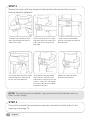
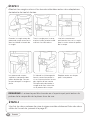
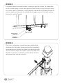
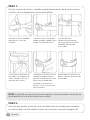
STEP 3
Secure the hook and loop straps & attached buckles around the top and
bottom banister adapters.
NOTE: The buckle can be rotated to any point around the banister post so
that it is out of sight.
Thread strap around banister
post and through the buckle
side of the strap.
On the top banister posts there
are locking tabs. Close these
to lock the strap position.
Pull the strap so that it is tight
and fold it over to connect the
hook side of the strap to the
loop side.
Using the hex key provided,
insert the key into the screw
and rotate it clockwise until the
screw is snug. This will tighten
the strap and secure the gate
to the banister post.
Once correctly positioned,
pull the strap tight around the
banister post.
Repeat all steps for other
banister post mounts.
STEP 4
Once both mounted level poles are securely mounted on both sides of the
opening, see page 14.

BUBBLE
LEVEL
MOUNTED
LEVEL POLE
English 11
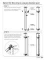
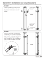
Option B2: Mounting to a square banister post
STEP 1
Place the square banister adapters
and banister corner adapters at the
top and bottom of the banister
STEP 2
Place the mounted level pole into the
appropriate grooves with the bottom
resting on the floor. Use the built in
bubble level to ensure the mounted
level pole is level and straight.
SQUARE
BANISTER
ADAPTER
SQUARE
BANISTER
ADAPTER
BANISTER
CORNER
PROTECTOR
MOUNTED
LEVEL POLE
BANISTER
CORNER
PROTECTOR

English12
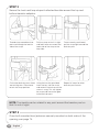
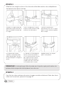
STEP 3
Secure the hook and loop straps & attached buckles around the top and
bottom banister adapters.
NOTE: The buckle can be rotated to any point around the banister post so
that it is out of sight.
Thread strap around banister
post and through the buckle
side of the strap.
On the top banister posts there
are locking tabs. Close these
to lock the strap position.
Pull the strap so that it is tight
and fold it over to connect the
hook side of the strap to the
loop side.
Using the hex key provided,
insert the key into the screw
and rotate it clockwise until the
screw is snug. This will tighten
the strap and secure the gate
to the banister post.
Once correctly positioned,
pull the strap tight around the
banister post.
Repeat all steps for other
banister post mounts.
STEP 4
Once both mounted level poles are securely mounted on both sides of the
opening, see page 14.

English 13
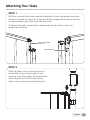
Attaching Your Gate
STEP 1
With the mounted level poles securely attached in their designated positions,
connect the gate by inserting its top and bottom hinge-side end pins into the
corresponding holes in the mounted level pole.
To detach the gate, squeeze the release tabs at the bottom of the top
hinge-side end pins.
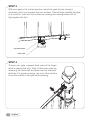
STEP 2
Slide the gate to the closed position by
expanding it across the length of your
opening. Insert the upper and lower latch-
side end pins into the corresponding
holes in the second mounted level pole.
RELEASE TAB
TOP HINGE-SIDE
END PIN

English14
STEP 3
With your gate in the locked position, adjust the gate foot by turning it
clockwise until it just touches the floor surface. This will help stabilize the gate
in its position. Lock the foot in place by rotating the locking wheel until its
tight against the foot.
STEP 4
To open your gate, squeeze both sides of the finger
latch to release the lock. Then, lift the entire gate up,
removing the latch-side end pins from the mounted
level bar. For easier opening, use your other hand to
lift up the middle of the gate while opening.
LOCKING WHEEL
GATE FOOT

English 15
CARE AND MAINTENANCE
Periodically check the gate for signs of damage, wear, or missing components.
Do not use if any part is missing, worn or damaged. Check the gate regularly to
ensure all the hardware and mountings are tightened. Do not use abrasive
cleaners or bleach. Clean by sponging with warm water and a mild detergent.
90 DAYS LIMITED WARRANTY
If, during the first 90 days after consumer purchase of the item, under reasonable
and non-commercial use and conditions of maintenance, it fails while owned by
the original purchaser because of the quality of materials or workmanship of finish
and assembly, Regalo International, LLC, will replace or repair it at Regalo’s option.
PROOF OF PURCHASE REQUIRED.

www.regalo-baby.com
Regalo International, LLC.
3200 Corporate Center Drive, Suite 100 / Burnsville, MN 55306, É.-U.
866.272.5274 (U.S. only) or 952.435.1080
Fabriqué en Chine
• LIRE TOUTES LES INSTRUCTIONS AVANT D’ASSEMBLER ET
D’UTILISER LA BARRIÈRE.
• CONSERVER CES INSTRUCTIONS POUR UNE UTILISATION
ULTÉRIEURE.
Barrière de sécurité
pour haut d'escalier
GUIDE D'UTILISATION MODÈLES : 1230, 1235, 1240

French 17
Barrière de sécurité
pour haut d'escalier
Avant d'utiliser le produit
Lire et suivre attentivement les instructions pour assurer une installation
conforme de la barrière et des rallonges. Une mauvaise installation risque
d'aboutir à une barrière branlante, ou qui se détache de l'ouverture. Vous êtes
responsable de la sécurité de votre enfant. Conserver ces instructions pour
consultation.
IMPORTANT
• Si la surface de fixation n'est pas une cloison sèche ou du bois, consulter
un spécialiste au sujet de l'installation.

French18
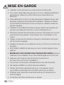
MISE EN GARDE
• Installer conformément aux instructions du fabricant.
• Pour éviter des blessures graves ou la mort, installez solidement
la barrière et utilisez-la conformément aux instructions du
fabricant.
• Des enfants sont morts ou ont été grièvement blessés lorsque des
barrières n'étaient pas solidement installées. Installez et utilisez
TOUJOURS les barrières comme indiqué en utilisant toutes les
pièces requises.
• CESSEZ D'UTILISER la barrière lorsque l'enfant est capable de
grimper par-dessus la barrière ou de la déloger/l'ouvrir.
• N'empilez jamais les barrières les unes sur les autres pour former
une barrière plus grande. Vous risquez de vous blesser ou de
mourir.
• Utilisez uniquement la barrière lorsque le mécanisme du loquet
est fermement engagé.
• Installez la barrière à une distance de 6po (15,24cm) du haut de
l'escalier.
• N'UTILISEZ JAMAIS la barrière pour tenir l'enfant éloigné d'une
piscine.
• MODÈLES 1230/1230DS/1235/1235DS/1240/1240DS: Barrière
destinée à une utilisation avec des enfants âgés de 6 à 24mois.
• Assurez-vous toujours que la barrière repose sur le
sol avant de commencer l'installation.
• Ce produit n'évitera pas nécessairement tous les accidents.
• Ne laissez JAMAIS un enfant sans surveillance.
• Vérifiez la barrière régulièrement pour vous assurer que la
quincaillerie et les supports de fixation sont bien en place.
• N'utilisez pas la barrière si des éléments sont manquants ou
endommagés.
• La barrière doit être montée par un adulte.

French 19
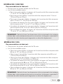
MODÈLE NO. 1230/1240
Recommandations du fabricant :
• Conçue pour les jeunes enfants de 6 à 24 mois
• Lors d'une installation entre :
• Deux murs sans plinthes, la largeur de l'ouverture doit être comprise entre
71 cm et 107 cm (28 po et 42 po).
• Deux murs et une plinthe, l'ouverture doit être comprise entre 74 cm et
109 cm (29 po et 43 po).
• Deux murs avec des plinthes, la largeur de l'ouverture doit être comprise
entre 76 cm et 111 cm (30 po et 43,5 po).
• Un poteau de rampe et un mur sans plinthe, la largeur de l'ouverture doit
être comprise entre 71 cm et 107 cm (28 po et 42 po).
• Un poteau de rampe et un mur avec plinthe, la largeur de l'ouverture doit
être comprise entre 74 cm et 108 cm (29 po et 42,5 po).
• Deux poteaux de rampe, la largeur de l'ouverture doit être comprise entre
72 cm et 107 cm (28,5 po et 42 po).
MODÈLE NO. 1235
Recommandations du fabricant :
• Conçue pour les jeunes enfants de 6 à 24 mois
• Lors d'une installation entre :
• Deux murs sans plinthes, la largeur de l'ouverture doit être comprise entre
86 cm et 137 cm (34 po et 54 po).
• Deux murs et une plinthe, l'ouverture doit être comprise entre 89 cm et
140 cm (35 po et 55 po).
• Deux murs avec des plinthes, la largeur de l'ouverture doit être comprise
entre 93 cm et 141 cm (36,5 po et 55,5 po).
• Un poteau de rampe et un mur sans plinthe, la largeur de l'ouverture doit
être comprise entre 88 cm et 137 cm (34,5 po et 54 po).
• Un poteau de rampe et un mur avec plinthe, la largeur de l'ouverture doit
être comprise entre 91 cm et 140 cm (36 po et 55 po).
• Deux poteaux de rampe, la largeur de l'ouverture doit être comprise entre
89 cm et 137 cm (35 po et 54 po).
REMARQUE : Selon la forme, les dimensions et les composants de montage
utilisés dans votre embrasure de porte ou ouverture, la longueur maximale et
minimale de cette barrière peut augmenter ou décroître légèrement.
REMARQUE : Selon la forme, les dimensions et les composants de montage
utilisés dans votre embrasure de porte ou ouverture, la longueur maximale et
minimale de cette barrière peut augmenter ou décroître légèrement.

G H I J
French20
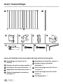
Avant l'assemblage
VEUILLEZ VÉRIFIER QUE VOUS DISPOSEZ DES ARTICLES SUIVANTS:
F Adaptateur de balustres rondes (1)
G Sangles velcro et boucles
attachées (4)
H Vis de montage mural de 3,8 cm
(1,5 po) (6)
I Vis de montage mural de 7,6 cm
(3 po) (6)
J Clé hexagonale (1)
DC
A B
E F
A Assemblage de la porte de la
barrière
B Poteaux de mise à niveau montés (2)
C Protecteurs de coin de balustre (16)
D Adaptateurs de balustres carrées (4)
E Cales d'espacement murales en
plastique (6)
A página está carregando...
A página está carregando...
A página está carregando...
A página está carregando...
A página está carregando...
A página está carregando...
A página está carregando...
A página está carregando...
A página está carregando...
A página está carregando...
A página está carregando...
A página está carregando...
A página está carregando...
A página está carregando...
A página está carregando...
A página está carregando...
A página está carregando...
A página está carregando...
A página está carregando...
A página está carregando...
A página está carregando...
A página está carregando...
A página está carregando...
A página está carregando...
A página está carregando...
A página está carregando...
A página está carregando...
A página está carregando...
-
 1
1
-
 2
2
-
 3
3
-
 4
4
-
 5
5
-
 6
6
-
 7
7
-
 8
8
-
 9
9
-
 10
10
-
 11
11
-
 12
12
-
 13
13
-
 14
14
-
 15
15
-
 16
16
-
 17
17
-
 18
18
-
 19
19
-
 20
20
-
 21
21
-
 22
22
-
 23
23
-
 24
24
-
 25
25
-
 26
26
-
 27
27
-
 28
28
-
 29
29
-
 30
30
-
 31
31
-
 32
32
-
 33
33
-
 34
34
-
 35
35
-
 36
36
-
 37
37
-
 38
38
-
 39
39
-
 40
40
-
 41
41
-
 42
42
-
 43
43
-
 44
44
-
 45
45
-
 46
46
-
 47
47
-
 48
48


Regalo 1235 Manual do usuário
- Tipo
- Manual do usuário
- Este manual também é adequado para
em outras línguas
- español: Regalo 1235 Manual de usuario
- français: Regalo 1235 Manuel utilisateur
- English: Regalo 1235 User manual
Artigos relacionados
Outros documentos
-
Jenn-Air YJMV9196CS0 Guia de instalação
-
 ClosetMaid Shelf Support Pole Guia de instalação
-
Klipsch CP-T Manual do usuário
-
 Zenna Home 34941SS Guia de instalação
-
Huffy SKM 1032 Manual do usuário
-
Chief ICXPFM2T03 Guia de instalação
-
Tannoy POLE MOUNT ADAPTOR Guia rápido
-
Carlson 0934 PW Manual do usuário
-
Vita 12x16 Valencia Attached Pergola Instruções de operação
-
Pottinger SYNKRO 4700 SH Instruções de operação

