
Installationsanleitung
Lüftungsgitter für Backofen
Bauform 60-450
J402.50-1
7.6.11 ZES
1
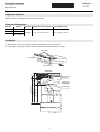
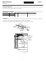
Siehe Installationsanleitungen für Glaskeramik-Kochfelder.
➤ Blendenträger links/rechts mit je 2 Schrauben mit Deckblech vorne verschrauben.
➤ Lüftungsgitter vorsichtig bis zum Anschlag einschieben und mit Klemmfeder befestigen.
Allgemeine Hinweise
Bausätze Lüftungsgitter
Art.-Nr. Farbe Bauform Erforderliche Nischengrösse Geräteabmessung
H6.0039 Nero
60-450 B × H = 60 × 49,2 cm B × H = 59,6 × 45,4 cm
H6.0041 ChromeClass
H6.0053
ChromeClass
(TouchClean)
Installation
A
Ansicht A
Klemmfeder
Lüftungsgitter
Glaskeramik-
Kochfeld
Kantenschutz
Lüftungsgitter
Blendenträger
Schrauben
Nische
Gerät
3
457
35
36
min. 20
492
454

Notice d’installation
Grille d’aération pour un four
Type de construction 60-450
J402.50-1
7.6.11 ZES
2
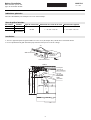
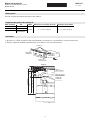
Voir notice d’installation pour champ de cuisson en vitrocéramique.
➤ Visser le support du panneau gauche/droite vissé avec 2 vis (de chaque côté) à la tôle de recouvrement devant.
➤ Pousser prudemment la grille d’aération jusqu’en butée et fixer par le ressort de serrage.
Indications générales
Sets de grille d’aération
No d’article Couleur Type de construction Dimension nécessaire de la niche Dimension de l’appareil
H6.0039 Nero
60-450 L × H = 60 × 49,2 cm L × H = 59,6 × 45,4 cm
H6.0041 ChromeClass
H6.0053
ChromeClass
(TouchClean)
Installation
A
Vue A
Grille
d’aération
Ressort
de serrage
Champ de
cuisson en
vitrocéramique
Protection d’arête
Grille d’aération
Support du
panneau
Vis
Niche
Appareil
3
457
35
36
min. 20
492
454

Istruzioni d’installazione
Griglia di ventilazione per forno
Forma costruttiva 60-450
J402.50-1
7.6.11 ZES
3
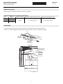
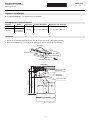
Vedere istruzioni d’installazione per piano di cottura vetroceramica.
➤ Avvitare il supporto del panello con 2 viti a sinistra e 2 a destra alla lamiera di coperturao davanti.
➤ Infilare con cautela la griglia di ventilazione fino all battuta d’arresto e fissare con molla di bloccaggio.
Indicazioni generali
Kit di montaggio per la griglia di ventilazione
Art. n. Colore Forma costruttiva Dimensione della nicchia richieste Dimensione dell’apparecchio
H6.0039 Nero
60-450 L × A = 60 × 49,2 cm L × A = 59,6 × 45,4 cm
H6.0041 ChromeClass
H6.0053
ChromeClass
(TouchClean)
Installazione
A
Veduta A
Griglia di
ventilatione
Molla di
bloccaggio
Piano di cottura
vetroceramica
Protezione
dello spigolo
Griglia di
ventilatione
Supporto del
panello
Viti
Nicchia
Apparecchio
3
457
35
36
min. 20
492
454

Installation instructions
Ventilation meshes for oven
Type of construction 60-450
J402.50-1
7.6.11 ZES
4
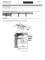
See installation instructions for ceramic-glass hobs.
➤ Mount the fascia mountings left and right with 2 screws to the cover plate in front.
➤ Carefully insert ventilation mesh as far as the stop and fix with the clamp spring.
General information
Mounting sets for ventilation meshes
Art. no. Colour Type of construction Required niche size Appliance dimensions
H6.0039 Nero
60-450 B × H = 60 × 49.2 cm B × H = 59.6 × 45.4 cm
H6.0041 ChromeClass
H6.0053
ChromeClass
(TouchClean)
Installation
A
View A
Clamp spring
Ventilation
mesh
Ceramic-glass
hob
Edge protector
Ventilation mesh
Fascia mounting
Screws
Niche
Appliance
3
457
35
36
min. 20
492
454

Manual de instalación
Rejilla de ventilación para horno
Modelo 60-450
J402.50-1
7.6.11 ZES
5
Ver las instrucciones de instalación para placas vitrocerámicas.
➤ Atornille el soporte de la pantalla a izquierda/derecha con 2 tornillos a tapadera delante.
➤ Introduzca cuidadosamente la rejilla de ventilación hasta el tope en sujete con resorte de sujeción.
Indicaciones generales
Kits de rejilla de ventilación
Núm. de artículo Color Modelo Tamaño de nicho necesario Dimensiones del aparato
H6.0039 Nero
60-450 A × H = 60 × 49,2 cm A × H = 59,6 × 45,4 cm
H6.0041 ChromeClass
H6.0053
ChromeClass
(TouchClean)
Instalación
A
Vista A
Resorte de
sujeción
Rejilla de
ventilación
Placa
vitrocerámica
Protección de
los bordes
Rejilla de
ventilación
Soporte de
la pantalla
Tornillos
mín. 25
Nicho
Aparato
3
457
35
36
min. 20
492
454

Manual de instalação
Grelhas de ventilação para os fornos
Modelo 60-450
J402.50-1
7.6.11 ZES
6
Consulte o manual de instalação para placas vitrocerâmicas.
➤ Aparafusar os suportes do painel no lado esquerdo/direito com 2 parafusos, respectivamente, à placa de tampa frente.
➤ Empurrar a grelha de ventilação cuidadosamente até ao batente e fixar com mola de aperto.
Notas gerais
Conjuntos de grelhas de ventilação
Núm. de artigo Cor Modelo Dimensões necessárias do nicho Dimensões do aparelho
H6.0039 Nero
60-450 L × A = 60 × 49,2 cm L × A = 59,6 × 45,4 cm
H6.0041 ChromeClass
H6.0053
ChromeClass
(TouchClean)
Instalação
A
Vista A
Mola de aperto
Grelha de
ventilação
Placa
vitrocerâmica
Protecção
contra arestas
Grelha de
ventilação
Suportes
do painel
Parafusos
mín. 25
Nicho
Aparelho
3
457
35
36
min. 20
492
454

Installatieaanwijzing
Ventilatierooster voor bakoven
Uitvoering 60-450
J402.50-1
7.6.11 ZES
7
Zie installatiehandleidingen voor glaskeramische kookvelden.
➤ Schroef de afschermkapdrager links/rechts met elk 2 schroeven aan de schermplaat vooraan.
➤ Schuif het ventilatierooster voorzichtig tot de aanslag naar binnen en bevestig met klemveer.
Algemene aanwijzingen
Bouwpakketten ventilatieroosters
Artikelnr. Kleur Uitvoering Vereiste nisgrootte Afmetingen van het toestel
H6.0039 Nero
60-450 B × H = 60 × 49,2 cm B × H = 59,6 × 45,4 cm
H6.0041 ChromeClass
H6.0053
ChromeClass
(TouchClean)
Installatie
A
Aanzicht A
Klemveer
Ventilatierooster
Glaskeramisch
kookveld
Kantbescherming
Ventilatierooster
Afschermkapdrager
Schroeven
Nis
Toestel
3
457
35
36
min. 20
492
454
-
 1
1
-
 2
2
-
 3
3
-
 4
4
-
 5
5
-
 6
6
-
 7
7


