Ingersoll Rand ELK100-2ND200 Informação do produto
- Tipo
- Informação do produto

EN
Product Information
Especicaciones del producto
ES
Spécications du produit
FR
Especicações do Produto
PT
Save These Instructions
Product Information
Form 47584686001
Edition 5
June 2018
© 2018 Ingersoll Rand
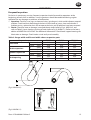
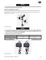
Electric Chain Hoist
ELK Series: 1/8 to 2 ton

2 Form 47584686001 Edition 5
EN
Only allow Ingersoll Rand trained technicians to perform maintenance on this product. For
additional information contact Ingersoll Rand factory or nearest Distributor.
For additional supporting documentation refer to Table 1.
Manuals can be downloaded from ingersollrandproducts.com
The use of other than genuine Ingersoll Rand replacement parts may result in safety hazards,
decreased performance and increased maintenance and will invalidate all warranties.
Original instructions are in English. Other languages are a translation of the original instructions.
Refer all communications to the nearest Ingersoll Rand oce or distributor.
Table 1: Product Information Manuals
Publication Part/Document Number
Product Safety Information Manual 47584687001
Product Parts Information Manual 47584688001
Product Maintenance Information Manual 47584689001

Form 47584686001 Edition 5 3
EN
PRODUCT SAFETY INFORMATION
Intended Use
ELK Series Electric Chain Hoists are designed to eciently raise and lower loads. These hoists are
designed for general industrial material handling operations, with freely suspended loads.
General Operating Conditions
Ambient Temperature: -15°C to +50°C.
Humidity: Max. 80% Relative Humidity.
Protection Class: IP 65.
Solenoid Compatibility: Immunity - Industrial Area.
CAUTION
The trolley must have at least the same lifting capacity as the electric chain hoist.
NOTICE
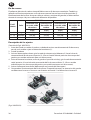
Refer to the Product Parts Information manual for components/parts listed below.
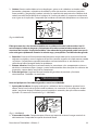
Housing
The housing and cover are made from robust cast aluminium, and cooling ns in the motor area
provide ecient cooling. The chain container can be attached to the compact housing. Holes
are provided for the chain screw connection of the power supply connecting cable and control
cable. The eye or hook suspension system is attached to the top ange.
Motor and Brake
ELK electric chain hoists are driven by asynchronous motors. Models are available in single and
dual speed. The motors are specically designed for hoist duty requirements and are rated
for lifting equipment. The windings of the motor correspond with insulation class F. The brake
system consists of a DC-powered multiple disk brake. In the de-energized state the braking
torque is provided by the compression spring.
Slip Clutch
The slip clutch is installed in a functional location downstream of the brake system. It protects
the chain hoist from overloading and provides additional function of an emergency limit stop
for the highest and lowest hook positions. The slip clutch complies with requirements of industry
standard, and is maintenance free.
Limit Switch
A geared limit switch is installed to control the highest and lowest chain positions. Intermediate
limit switch contacts with automatic disconnection can be optionally retrotted.
Electrical Controller
The electric chain hoists are equipped with a 42 V pendant controller as standard. The emergency
stop contactor disconnects all three main power legs from the power source when the
Emergency-Stop button is pressed.

4 Form 47584686001 Edition 5
EN
Chaindrive
The hoist is equipped with a 5 pocket liftwheel and uses case carborized highly heat treated load
chain for long life. Chain guides are easily removed for inspection. All hooks are equipped with
a safety latch.
Gearbox
The three stage, closed spur gearing is designed for lifting gear requirements. The gear wheels
are mounted on roller bearings and have continuous lubrication. The helical gearing reduces
running noise to a minimum.
Control Switch
The standard equipment of the electric chain hoist includes a control switch (raise/ lower with
emergency stop). The automatically disconnecting emergency stop contact of the control switch
directly opens the power circuit which powers the contactors. A 4-button or 6-button control
switch is attached to the motorized trolley as required for additional movement directions.

Form 47584686001 Edition 5 5
EN
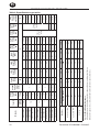
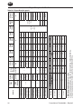
PRODUCT SPECIFICATIONS
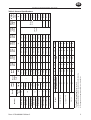
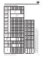
Table 2: General Specications
Model(s)
Capacity
Lifting
Speed
No. of
Chain
Falls
Motor
Power
115V
1-PH
60 Hz
230V
1-PH
60 Hz
230 V
3-PH
60 Hz
460 V
3-PH
60 Hz
575 V
3-PH
60 Hz
380 V
3-PH
50 Hz
ELK25-
1NS25
FLEX
Dead
Weight
(10 ft.
Lift)
Metric
Tons
ft/min HP A lb
ELK25-1ND12 1/8 32 / 8
1
0.6 / 0.14
- - 4.2 / 3.5 2.4 / 1.6 1.4 / 1.0
Contact
Factory
Contact
Factory
37.4
ELK25-1ND25
1/4
32 / 8
0.6 / 0.14
- - 4.2 / 3.5 2.4 / 1.6 1.4 / 1.0 37.4
ELK50-1HD25 63 / 16 1.2 / 0.3 - - 5.6 / 4.0 3.2 / 1.9 2.0 / 1.3 57.3
ELK25-1NS25 1PH 16 0.4 9.5 3.7 - - - 37.4
ELK50-1NS25 1PH 32 0.9 17.3 8.0 - - - 57.3
ELK50-1ND50
1/2
32 / 8
1
1.2 / 0.3 - - 5.6 / 4.0 3.2 / 1.9 2.0 / 1.3 57.3
ELK50-1NS50 1PH 16 0.9 17.3 8.0 - - - 57.3
ELK50-2ND100
1
16/4
2
1.2 / 0.3 - - 5.6 / 4.0 3.2 / 1.9 2.0 / 1.3 61.7
ELK50-2NS100 1PH
8 0.9 17.3 8.0 - - - 61.7
ELK100-1ND100
1 31 / 8 1 3.7/0.9 - -
16.7 / 11.2
7.3 / 4.7 5.3 / 3.5 - 136.68
ELK100-2ND200
2 16 / 4 2 3.7/0.9 - -
16.7 / 11.2
7.3 / 4.7 5.3 / 3.5 - 145.50
ELK100-1HD50
1/2 63 / 16 1 3.7/0.9 - -
16.7 / 11.2
7.3 / 4.7 5.3 / 3.5 - 136.68
Model
Measuring Distance 1m 2m 4m 8m 16m
Measurement Type dBA
ELK 25/50 ELK
a) 65 62 59 56 53
b) 65 59 53 47 41
ELK 25/50 1PH
a) 76 73 70 67 64
b) 76 70 64 58 52
ELK 100
a) 80 77 74 71 68
b) 80 74 68 62 56
The Sound Pressure Level was measured,
a) During operation of electric chain hoists on factory site.
b) During open-air operation of electric chain hoists.

6 Form 47584686001 Edition 5
EN
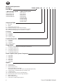
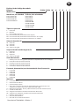
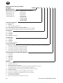
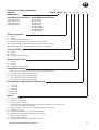
Model Code Explanation:
Example: ELK50-1NS50 M1 21 17 B 1 C
Base Model
1 phase Single-speed 3 phase Dual-speed
ELK25-1NS25 1PH ELK25-1ND12
ELK50-1NS25 1PH ELK25-1ND25
ELK50-1NS50 1PH ELK50-1HD25
ELK50-2NS100 1PH ELK50-1ND50
ELK50-2ND100
ELK100-1ND100
ELK100-2ND200
ELK100-1HD50
Suspension Type
E = Eye Bolt
H = Hook
P = Plain Trolley (“PT” Series)
M1 = Motorized Trolley (normal speed 47 fpm)
M2 = Motorized Trolley (normal / dual speed 47 / 16 fpm)
M4 = Motorized Trolley (High / dual speed 79/ 24 fpm)
Lift (feet)
10 = Standard
15 = Standard
20 = Standard
XX = Specify Length
Pendent Drop (feet)
6 = Standard
11 = Standard
16 = Standard
XX = Specify Length
Flange Width
- = Eye bolt or hook mount (see catalog for specication)
A = See ange width chart
B = See ange width chart
C = See ange width chart
D = See ange width chart
Power supplier (volts / phase / frequency)
1 = 115/1/60
2 = 230/1/60
3 = 230/3/60
4 = 460/3/60
5 = 575/3/60
6 = 380/3/50
Options
B = Trolley brake
C = Chain container
E = External strain relief
F = XX, Specify power cord length
(Standard is 15ft on E, H, and P and 3 ft on M1-M4 suspensions)
H = Handy Handle - ELKH25 & 50 only (12 ft Max. Lift)
K = 110 volt control
P2 = Pendent with extra vertical aligned buttons
P4 = Pendent with 4 extra vertical aligned buttons
Y = Bullard top hook
Z = Bullard bottom hook
V = Hoist with variable frequency drive

Form 47584686001 Edition 5 7
EN
OPERATIONAL PARAMETERS
Electric chain hoists are manufactured in accordance with the latest technical developments along
with the latest technical safety regulations and specications, and are tested for safety by
the
manufacturer. The operational parameters of the electric chain hoist also encompass the compliance
of the safe operating practices, maintenance information and parts information manuals.
The operational parameters do not include:
● Exceeding the dened load capacity,
● Diagonal pulling of the load or yarding,
● Excessive impact or lifting of guided loads.
Excessive inching operations, ground mooring and running against limit switches, should be avoided.
Operating temperature is -15° to 50° C ( 5° F to 122° F).
Hoists are rated at H4 Duty Class in accordance with ASME HST-1-2012.
The manufacturer accepts no responsibility for any damage to this equipment, resulting from
abnormal operating practices.
START-UP
DANGER
Mechanical adjustments should be performed by authorized designated personnel.
CAUTION
The operating sta must carefully read the operating instructions of the electric chain hoists
before its initial operation and carry out all checks. Only when a safe operation has been
established may the device be put into operation. Unauthorized persons may not operate the
device or perform any work with the help of the same.
Transport and Assembly
For the transport and assembly of the electric chain hoists, the safety direction for handling with
loads are to be followed. Refer to Product Safety Information Manual.
The electric chain hoists must be assembled by qualied sta, always bearing in mind the accident
prevention directions. Before assembly the electric chain hoist must be stored in an enclosed
room or covered area. Should the electric chain hoist be destined for operation outdoors, then it
is recommended that a protection roof is erected to shield it from the inuences of the weather.
Whenever possible, the electric chain hoist should be transported in its original packaging. It is
recommended that the assembly and connection of the electric chain hoist is conducted on-site
by qualied personnel.

8 Form 47584686001 Edition 5
EN
INSTALLATION
Prior to installing the hoist, carefully inspect components for possible shipping damage.
Hoists are supplied fully lubricated from the factory. Refer to “Lubrication,” section for
recommended oils and lubrication intervals. Lubrication
of the load chain is recommended
before initial hoist operation.
WARNING
● A falling load can cause injury or death. Before installing, read Product Safety
Information Manual.
● Owners and users are advised to examine specic, local or other regulations, including
American National Standards Institute and/or OSHA Regulations which may apply to a
particular type of use of this product before installing or putting hoist to use.
● The strength of the hoist, chain and hooks can be aected by chemically active environments,
such as caustic or acid substance fumes. A qualied person should be consulted before
hoists are used in chemically active environments.
Mounting
Always make certain the supporting member from which the hoist is suspended is strong
enough to support the weight of the hoist plus the weight of the maximum rated load plus a
safety factor (consult a structural engineer).
If the hoist is suspended by a top hook, the supporting member should rest completely within
the saddle of the hook and be centered directly above the hook shank. Do not use a supporting
member that tilts the hoist.
Hook Mounted Hoist
Place hook over mounting structure. Make sure hook latch is engaged.
Trolley Mounted Hoist
When installing a trolley on a beam, measure beam ange and temporarily install trolley on
hoist to determine the exact distribution and arrangement of the spacers. Adjust spacers in
accordance with trolley manufacturer’s literature to provide the correct distance between the
wheel ange and the beam. The number of spacers between the trolley side plate and mounting
lug on hoist must be the same in all four locations in order to keep the hoist centered under the
I-beam. The remaining spacers must be equally distributed on the outside of the side plates.
WARNING
At least one mounting spacer must be used between the head of each trolley bracket bolt
and the trolley bracket and between each trolley bolt nut and the trolley bracket. Failure to
do this could cause the hoist to fall when used improperly.
Make sure trolley bolts or nuts are torqued in accordance with manufacturer’s specications.
For installation of hoist and trolley on beam, make certain the side plates are parallel and vertical.
After installation make sure beam stops are in place, operate trolley over entire length of beam
with a capacity load suspended 4 to 6 inches (10 to 15 cm) o the oor.

Form 47584686001 Edition 5 9
EN
CAUTION
To avoid an unbalanced load which may damage the trolley, the hoist must be centered
under the trolley.
NOTICE
Trolley wheels ride on the top of the lower ange of the beam.
Power Connection
DANGER
Electrical connection adjustments should only be performed by authorized specialists.
The main connection cable, fuse and the switch must be installed by the customer before connecting
the electric chain hoist to the mains power supply.
A 4-wire cable with a ground protective conductor is needed to provide the power supply for three-
phase models. A 3-wire cable with a protective conductor is adequate for single-phase models. The
length and the gage must be determined to support the power consumption of the electric chain hoist.
DANGER
The ground conductor must not carry any power. With motorized trolley operation, the
power supply is enclosed in a terminal box on the drive motor. With the installation of a
motor protector, the load plate voltage of the electric chain hoist must be noted.
CAUTION
Checking direction of rotation: If the direction of rotation does not correspond with the
button symbols on the control switch, power supply wires L1 and L2 must be swapped
around.
WARNING
Electrical Connections if not tight and secure, will cause a re. During installation the
electrician must make sure that all electrical connections including the ground connection
are secure. Make sure all junction boxes and switch enclosures are adequately sealed and
protected for the environmental conditions to be encountered.
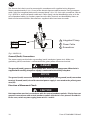
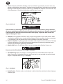
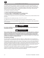
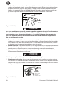
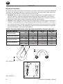
NOTICE
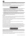
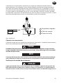
Make sure wire connection at the terminal is in accordance with Fig 1. MHP3318.

10 Form 47584686001 Edition 5
EN
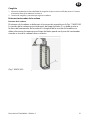
The electric chain hoist must be connected in accordance with supplied wiring diagrams.
Remove approximately 3/8 in. (9 mm) of the electrical power cable protective casing to expose
cable. Open the integrated clamp with a narrow blade 1/8 in. (3.5 mm) wide screwdriver, refer to
Fig 1. MHP3318, and install power cable end. Cables (leads) can be identied by color, or in the
case of pendant cables, by numbers taped to each cable. Terminals are identied by letters or
labels on the terminal blocks. Manufacturer-supplied cables have bare wire ends.
8-9 mm
Integrated Clam
p
Power Cable
Screwdriver
1
2
3
(Fig 1. MHP3318)
Ground (Earth) Connections
The power supply cord includes a grounding (earth) conductor (green wire). Make sure
grounding (earth) conductor is connected to the green/yellow connector terminal.
DANGER
The ground (earth), green or green/yellow wire, must not carry any power. When hoist is
supplied with a trolley, the power supply is connected at the trolley relay box.
NOTICE
The ground (earth) connection must be wired to the green/yellow ground (earth) connection
terminal. Ground (earth) wire of the terminal power supply is connected to the yellow/green
wire (PE).
Direction of Movement Check
CAUTION
Hoist operation must be in accordance with the control pendant symbols. If hoist does not
operate in accordance with control pendant symbols then hoist is mis-phased. Should this
be the case, switch any two supply power wires L1 and L2.

Form 47584686001 Edition 5 11
EN
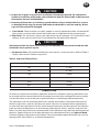
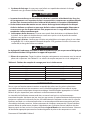
Load Chain
CAUTION
● Only use original chains supplied by manufacturer.
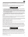
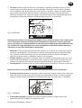
● Welded seam of the chain links must face inward on the chain wheel (Refer to Fig 2. MHP4157).
● The geared limit switch must be mechanically disabled in order to install in the chain,
see section on Limit Switch.
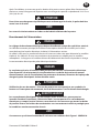
(Fig 2. MHP4157)
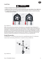
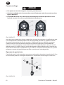
Before start-up and during operation, the load chain must be oiled along its full length. Oil
must
constantly be present on the internal, contacting and rubbing surfaces of the chain links.
Lubrication is carried out by submersion or with an oil can, using a creeping gear oil. The end
of the chain (1) should be attached to a exible piece of wire or chain pulling loop (2) and fed
through the chain wheel (3) of the electric chain hoist. Run hoist slowly in the lifting direction,
the chain will be pulled in correctly according to Fig 2. MHP4157. The lifting height must be
adjusted such that the hook ttings lie on the ground in the lowest hook position.
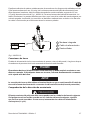
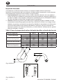
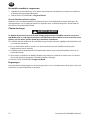
Single fall operation
The load hook (1) is connected to the chain with a single fall hook clamp (2). For the power
transmission, the mounting of the bolt (3) is important (see Fig 3. MHP4158).
(Fig 3. MHP4158)

12 Form 47584686001 Edition 5
EN
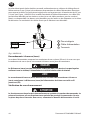
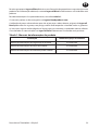
NOTICE
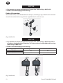
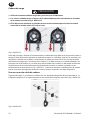
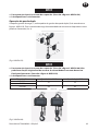
● Pay attention to correct arrangement of suspension. (Refer to Fig 4. MHP4159).
● Make sure to thoroughly grease bearings.
Double fall operation
Attach load hook (1) to the double fall hook clamp (2) according to Fig 4. MHP4159. Fix the load
size of chain end to the housing with the supplied bolts (3) and screw (4).
(Fig 4. MHP4159)
NOTICE
● Pay attention to correct arrangement of suspension. (Refer to Fig 5. MHP4160). There
must be no longitudinal chain twisting. The chain end must be attached to the housing.
(Refer to Fig 4. MHP4159)
● Make sure to thoroughly grease bearings.
Type of Hoist Single fall ‘k1’ Double fall ‘k2’
ELK25
41 52
ELK50
ELK100 43 62
(Fig 5. MHP4160)

Form 47584686001 Edition 5 13
EN
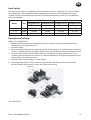
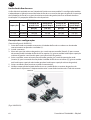
Limit Switch
The electric chain hoist is equipped with a geared limit switch as standard. This is also suitable
for normal limit switch operation with a high degree of accuracy. The operation of the limit
switches (highest and lowest hook position) must be checked during start-up. Three dierent
ratios are available.
Ratios Color
ELK25/50 ELK 100
Single Fall Lift Double Fall Lift Single Fall Lift Double Fall Lift
ft (m) ft (m) ft (m) ft (m)
i = 1:1 Black 66 (20) 33 (10) 98 (30) 49 (15)
i = 1:3 Yellow 198 (60) 99 (30) 295 (90) 147 (45)
i = 1:6 Blue 396 (120) 198 (60) 630 (192) 315 (96)
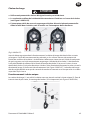
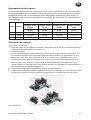
Description of settings
(Refer to Fig 6. MHP3323).
1. Before installing the chain or changing the chain, the limit switch must be mechanically
disabled by securing the rocker (1).
2. Install the chain.
3.
Move to highest hook position, rotate red ratchet wheel (front) (2) to switching cam of top Limit
Switch (3); (rotate clockwise for higher hook position and anticlockwise for lower hook position).
4. Activate rocker, move to lowest hook position, rotate green Switching Wheel (rear) (4) to
switching cam of bottom Limit Switch (5); (rotate anticlockwise for higher hook position and
clockwise for lower hook position).
5. Activate rocker (must engage in switch wheel).
6. Check operation of limit switch; the end stop and the hook ttings must not touch the
housing. Keep a minimum of 12 chain links from the housing.
(Fig 6. MHP3323)

14 Form 47584686001 Edition 5
EN
Chain Bucket
1. Move chain out at load side until limit switch is activated. Attach free end of chain at housing.
2. Attach chain bucket and allow chain to run in.
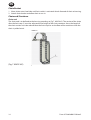
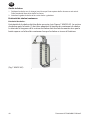
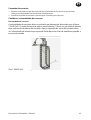
Chain end/ Container
Chain end:
The chain end is to be xed to the housing according to Fig 7. MHP4162. The section of the chain
after the limit stop (1) must be adjusted to the height of the chain container. Here, the length of
the chain section must be selected that the limit stop lies on the oor of the container when the
chain is pulled into it.
(Fig 7. MHP4162)

Form 47584686001 Edition 5 15
EN
INSPECTION
Frequent Inspection
For hoists in continuous service, frequent inspection should be made by operators at the
beginning of each shift. In addition, visual inspections should be conducted during regular
operation for any damage or evidence of malfunction.
1.
Operation: Check for visual signs or abnormal noises (grinding etc.) which could indicate a potential
problem. Check load chain feed through the hoist. If chain binds or jumps, clean and lubricate. If
problem persists, replace the chain. Do not operate the hoist until all problems have been corrected.
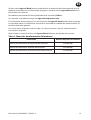
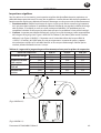
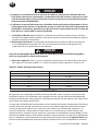
2. Hooks: Check for wear or damage, increased throat width (refer to Fig 8. MHP4161 and
refer to Table 2), bent shank or twisting of hook (refer to Fig 9. MHP0111). Refer to the latest
edition of ASME B30.10 “HOOKS” for additional information. Check hook support bearings for
lubrication or damage. Check hooks swivel easily and smoothly.
Table 2. Gauge width and Discard width values suspension parts
Suspension part ELK 25 ELK 50 ELK 100
Load hook
H
(mm) 28.0 28.0 35.5
H min. (mm) 26.6 26.6 33.8
Hook suspension
H
(mm) 28.0 28.0 35.5
H min. (mm) 26.6 26.6 33.8
Eyebolt suspension
H
(mm) 15.0 15.0 20.0
H min. (mm) 14.3 14.3 19.0
Hook opening
I
(mm) 34.5 34.5 42.6
I max.
(mm) 37.9 37.9 46.8
Twisted
Do Not Use
Normal
Can Be Used
H
I
H
(Fig 8. MHP4161)
(Fig 9. MHP0111)

16 Form 47584686001 Edition 5
EN
3.
Chain: Examine each link for bending, cracks in weld areas or shoulders, traverse nicks and
gouges, weld splatter, corrosion pits, striation (minute parallel lines) and chain wear, including
bearing surfaces between chain links (refer to Fig 10.
MHP0102
). Replace a chain that fails any
of the inspections. Check chain lubrication and lubricate if necessary.
(
Fig 10.
MHP0102)
CAUTION
Excessive wear or stretching may not be apparent from visual observation. At any indication
of wear or stretching inspect the chain in accordance with instructions in “Periodic Inspection”.
A worn load chain may cause the load sheave to wear rapidly. Inspect the load sheave and
replace if damaged or worn.
4. Controls: During operation of hoist, verify response to pendant is quick and smooth. Make
sure that the controls return to neutral when released. If hoist responds slowly or movement
is unsatisfactory, do not operate hoist until all problems have been corrected.
5. Electrical System: Visually inspect all connections and components for indication of damage
or loose connections. Shut o and disconnect power prior to removing inspection covers,
repairing any damage or tightening connections.
6. Hook Latch: Make sure the hook latch is present and operating. Replace if necessary.
CAUTION
Do not use hoist if hook latch is missing or damaged.
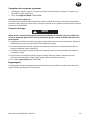
7. Chain Reeving: Make sure welds on standing links face in toward load sheave. Reinstall
chain if necessary. On double fall hoists, make sure chain is not capsized, twisted or kinked.
Adjust as required. Refer to Fig 11. MHP0043.
Make certain
bottom block
has NOT been
flipped through
the chain falls
A
(Fig 11. MHP0043)
8. Brake System: Check to make sure the brake is able to hold the rated load without slippage.
Check air gap.

Form 47584686001 Edition 5 17
EN
CAUTION
● Inspect for air gaps in case of noise or vibration from brake solenoid. For information
related to inspection of DC brake, refer to Brake Air Gap (DC Brake) table in Maintenance
Information manual (47584689001).
● Humming of the motor or slow lifting speed indicates oily or sticky brake discs or worn
or damaged brake cage. Dismantle and make sure brake discs are clean and dry. Brake
cage must be replaced if damaged.
9. Limit Switch: Check to make sure chain stopper is securely attached to chain. On double fall
hoists make sure lower hook sheave block capscrews are tightened to the correct torque.
10. Slip Clutch: The slip clutch is factory pre-adjusted to slip at a nominal 125% of the hoist rated
capacity. If the wear resistant lining is overheated the slip load will be reduced.
CAUTION
Adjustment of the slip clutch should only be attempted by service personnel and must be
recorded in the inspection report.
11. Suspension Parts: All statically loaded parts are known as suspension parts. Refer to Table 3.
Torque values are for Grade 8.8 capscrews.
Table 3. Capscrew Torque Chart
Dimension Torque Value
M4 3.3 Nm
M5 6.5 Nm
M6 10 Nm
M8 24 Nm
M10 48 Nm
M12 83 Nm
LUBRICATION
To make sure continued satisfactory operation of the hoist, all points requiring lubrication must
be serviced with the correct lubricant at the proper time interval as indicated for each assembly.
Correct lubrication is one of the most important factors in maintaining ecient operation.
The lubrication intervals recommended in this manual are based on intermittent operation of
the hoist eight hours each day, ve days per week. If the hoist is operated almost continuously
or more than the eight hours each day, more frequent lubrication will be required. The lubricant
types are based on operation in an environment relatively free of dust, moisture, and corrosive
fumes. Use only those lubricants recommended. Other lubricants may aect the performance of
the hoist. Approval for the use of other lubricants must be obtained from your Ingersoll Rand
Technical Support Department or distributor. Failure to provide proper lubrication may result in
damage to the hoist and/or its associated components.

18 Form 47584686001 Edition 5
EN
Hook and Suspension Assemblies
1. Lubricate the lower hook and hook latch pivot points. Hook and latch should pivot freely.
2. Use Ingersoll Rand 47580935001 oil.
Trolley (optional feature)
Refer to the manufacturer’s literature for correct lubrication. For additional information on
motorized trolleys, refer to Parts, Operation and Maintenance Manual Form Number MHD56108.
Load Chain
WARNING
Failure to maintain a clean and well lubricated load chain will result in rapid load chain wear that
can lead to chain failure which can cause severe injury, death or substantial property damage.
● Lubricate each link of the load chain weekly. Apply new lubricant over existing layer.
● In severe applications or corrosive environments, lubricate more frequently than normal.
● Lubricate hook latch pivot point with the same lubricant used on the load chain.
● To remove rust or abrasive dust build-up, clean chain with an acid free solvent. After cleaning,
lubricate the load chain.
● Use Ingersoll Rand 47580935001 oil.
Gears
The gear compartment is lled with grease at the factory. Replacement of the grease for the life
of the hoist is not required.

Formulario 47584686001 ª Edición 5 19
ES
Permita solo a Ingersoll Rand técnicos profesionales la realización del mantenimiento de este
producto. Para obtener más información, póngase en contacto con la Ingersoll Rand fábrica o
distribuidor más cercanos.
Para obtener documentación de respaldo adicional, consulte la Tabla 1.
Los manuales se pueden descargar en ingersollrandproducts.com
El uso de piezas de recambio que no sean originales de Ingersoll Rand podría poner en peligro
la seguridad, reducir el rendimiento, aumentar la necesidad de cuidados de mantenimiento, así
como invalidar toda garantía.
Las instrucciones originales están en inglés. Las demás versiones son una traducción de las
instrucciones originales.
Remita todas las comunicaciones a la Ingersoll Rand ocina o distribuidor más cercano.
Tabla 1: Manuales de información del producto
Publicación Número de pieza/ documento
Manual de información de seguridad del producto 47584687001
Manual de información de piezas del producto 47584688001
Manual de información de mantenimiento del producto 47584689001

20 Formulario 47584686001 ª Edición 5
ES
Información de seguridad sobre el producto
Uso indicado:
Los polipastos eléctricos de cadena de la Serie ELK están diseñados para elevar y bajar cargas de
manera eciente. Estos polipastos están diseñados para operaciones generales de manipulación
de cargas suspendidas libremente en ambientes industriales.
Condiciones generales de uso
Temperatura ambiente: -15 °C a +50 °C.
Humedad: Máx. 80 % de humedad relativa.
Clase de estanqueidad: IP 65.
Compatibilidad con solenoides: Inmunidad - Zona industrial.
PRECAUCIÓN
El carro debe tener, como mínimo, la misma capacidad de carga que el polipasto eléctrico
de cadena.
AVISO
Consulte el manual de información sobre las piezas del producto para obtener detalles
sobre los componentes y las piezas que se indican a continuación.
Carcasa
La carcasa y la cubierta están hechas de aluminio fundido de gran resistencia, y las aletas disipadoras
en la zona del motor permiten un enfriamiento eciente. El contenedor de la cadena se puede unir a
la carcasa compacta. Se proporcionan oricios para la conexión del cable de alimentación y el cable
de control. El sistema de suspensión con argolla o gancho se conecta a la brida superior.
Motor y freno
Los polipastos eléctricos de cadena ELK son impulsados por motores asíncronos. Se dispone
de modelos de una y dos velocidades. Los motores están especícamente diseñados para las
exigencias de los polipastos y son aptos para izar equipos. Los arrollamientos del motor tienen
aislamiento clase F. El sistema de frenado consiste en un freno de discos múltiples alimentado
por CC. En el estado desenergizado, un tornillo de compresión provee el torque de frenado.
Embrague deslizante
El embrague deslizante está instalado en una ubicación funcional aguas abajo del sistema de
frenado. Este embrague protege al polipasto contra sobrecargas y, adicionalmente, funciona
como tope de emergencia en las posiciones mínima y máxima del gancho. El embrague deslizante
cumple con las exigencias de los estándares industriales y no requiere mantenimiento.
Fin de carrera
El sistema cuenta con un n de carrera mecánico para controlar las alturas máxima y mínima de
la cadena. Como complemento adicional, se pueden instalar posteriormente contactos de n de
carrera intermedios con desconexión automática.
A página está carregando...
A página está carregando...
A página está carregando...
A página está carregando...
A página está carregando...
A página está carregando...
A página está carregando...
A página está carregando...
A página está carregando...
A página está carregando...
A página está carregando...
A página está carregando...
A página está carregando...
A página está carregando...
A página está carregando...
A página está carregando...
A página está carregando...
A página está carregando...
A página está carregando...
A página está carregando...
A página está carregando...
A página está carregando...
A página está carregando...
A página está carregando...
A página está carregando...
A página está carregando...
A página está carregando...
A página está carregando...
A página está carregando...
A página está carregando...
A página está carregando...
A página está carregando...
A página está carregando...
A página está carregando...
A página está carregando...
A página está carregando...
A página está carregando...
A página está carregando...
A página está carregando...
A página está carregando...
A página está carregando...
A página está carregando...
A página está carregando...
A página está carregando...
A página está carregando...
A página está carregando...
A página está carregando...
A página está carregando...
A página está carregando...
A página está carregando...
A página está carregando...
A página está carregando...
A página está carregando...
A página está carregando...
A página está carregando...
A página está carregando...
-
 1
1
-
 2
2
-
 3
3
-
 4
4
-
 5
5
-
 6
6
-
 7
7
-
 8
8
-
 9
9
-
 10
10
-
 11
11
-
 12
12
-
 13
13
-
 14
14
-
 15
15
-
 16
16
-
 17
17
-
 18
18
-
 19
19
-
 20
20
-
 21
21
-
 22
22
-
 23
23
-
 24
24
-
 25
25
-
 26
26
-
 27
27
-
 28
28
-
 29
29
-
 30
30
-
 31
31
-
 32
32
-
 33
33
-
 34
34
-
 35
35
-
 36
36
-
 37
37
-
 38
38
-
 39
39
-
 40
40
-
 41
41
-
 42
42
-
 43
43
-
 44
44
-
 45
45
-
 46
46
-
 47
47
-
 48
48
-
 49
49
-
 50
50
-
 51
51
-
 52
52
-
 53
53
-
 54
54
-
 55
55
-
 56
56
-
 57
57
-
 58
58
-
 59
59
-
 60
60
-
 61
61
-
 62
62
-
 63
63
-
 64
64
-
 65
65
-
 66
66
-
 67
67
-
 68
68
-
 69
69
-
 70
70
-
 71
71
-
 72
72
-
 73
73
-
 74
74
-
 75
75
-
 76
76


Ingersoll Rand ELK100-2ND200 Informação do produto
- Tipo
- Informação do produto
em outras línguas
Outros documentos
-
GYS POWER PULLER 4T Ficha de dados
-
 Total TLH1952 Guia de usuario
-
Ega Master 00657 Manual do proprietário
-
Ingersoll-Rand Free Standing Workstation Cranes Informação do produto
-
Beta 8143 Instruções de operação
-
Yamaha S12 Manual do proprietário
-
Invacare Birdie Plus Manual do usuário
-
Nexo M6 Manual do usuário
-
-
