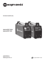
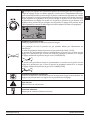
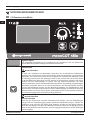
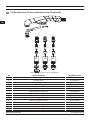
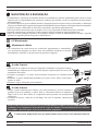
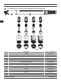
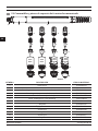
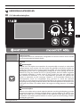
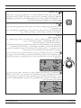
Magmaweld MONOCUT 45i Plasma Cutting Mechanized Manual do proprietário
- Tipo
- Manual do proprietário

monoCUT 45ix
monoCUT 45i
(+90) 444 93 53
magmaweld.com
info@magmaweld.com (+90) 538 927 12 62
USER MANUAL

All rights reserved. It is prohibited to reproduce this documentation, or any part thereof, without the prior written
Magma Mekatronik may modify the information and the images without any prior notice.

3monoCUT 45ix / monoCUT 45i
INVERTER PLASMA CUTTING MACHINE EN
PLASMASCHNEIDER MIT INVERTERTECHNOLOGIE DE
MACHINE DE DÉCOUPE PLASMA À ONDULEUR FR
RU
MÁQUINA DE CORTE POR PLASMA TIPO INVERTER
MÁQUINA DE CORTE POR PLASMA INVERSOR
PT
ES
INVERTER PLASMASNIJMACHINE
TR
AR
NL

EN
4
www.magmaweld.comUSER MANUAL
monoCUT 45ix / monoCUT 45i
1
1.1
1.2
1.3
1.4
1.5
2
2.1
2.2
2.3
2.4
2.5
2.5.1
2.5.2
2.5.3
2.6
2.7
2.8
2.8.1
3
3.1
3.2
4
4.1
4.2
4.3
5
5.1
5.2
5.3
5.4
5.5
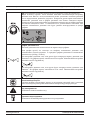
SAFETY PRECAUTIONS
TECHNICAL INFORMATION
General Information
Machine Components
Product Label
Technical Data
Accessories
INSTALLATION
Delivery Control
Installation and Operation Recommendations
Mains Plug Connection
Connection to Mains
Connections for Plasma Cutting
Gas Connections
Grounding Pliers Connections
Torch Connections
Placing Consumables
Pilot Arc
Remote Control
Communication
OPERATION
User Interface
Torch Usage
MAINTENANCE AND SERVICE
Maintenance
Troubleshooting
Error Codes
ANNEX
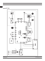
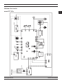
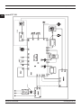
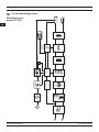
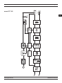
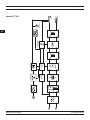
Plasma Cutting Automation Connection Diagram
Manual Torch Consumables and Spare Parts
Mechanized Torch Consumables and Spare Parts
Plasma Cutting Machine Spare Parts List
Connection Diagrams
5
11
11
13
14
14
15
15
16
16
16
16
16
17
17
18
18
19
20
24
25
26
28
30
31
32
33
35
CONTENTS
Contents

EN
5
www.magmaweld.com USER MANUAL
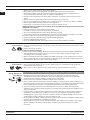
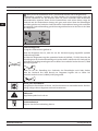
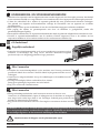
monoCUT 45ix / monoCUT 45i Safety Precautions
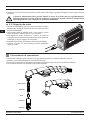
Be Sure To Follow All Safety Rules In This Manual!
• Safety symbols found in the manual are used to identify potential hazards.
• When any one of the safety symbols are seen in this manual, it must be understood that there is
a risk of injury and the following instructions should be read carefully to avoid potential hazards.
• The possessor of the machine is responsible for preventing unauthorized persons from
accessing the equipment.
• Persons using the machine must be experienced or fully trained in welding / cutting they have to
read the user manual before operation and follow the safety instructions.
Explanation Of Safety
Information
• Read the user manual, the label on the machine and the safety instructions carefully.
• Make sure that the warning labels on the machine are in good condition. Replace missing and
damaged labels.
• Learn how to operate the machine, how to make the checks in a correct manner.
• Use your machine in suitable working environments.
• Improper changes made in your machine will negatively affect the safe operation and its
longevity.
• The manufacturer is not responsible for the consequences resulting from the operation of the
Comprehending Safety
Precautions
Explanation Of Safety
Symbols
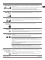
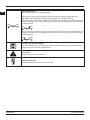
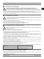
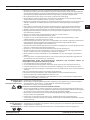
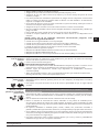
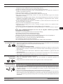
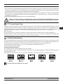
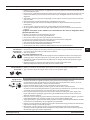
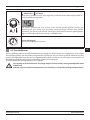
ATTENTION
Indicates a potentially hazardous situation that could cause injury or damage.
In case if no precaution is taken, it may cause injuries or material losses / damages.
IMPORTANT
DANGER
Indicates a serious danger. In case if not avoided, severe or fatal injuries may occur.
Make certain that the installation procedures comply with national electrical standards
persons.
• Wear dry and sturdy insulated gloves and working apron. Never use wet or damaged gloves and
working aprons.
operator must be protective against sparks, splashing and arc radiation.
• Do not work alone. In case of a danger make sure you have someone for help in your working
environment.
• Do not touch the electrode with the bare hand. Do not allow the electrode holder or electrode to
come in contact with any other person or any grounded object.
• Never touch parts that carry electricity.
• Never touch the electrode if you are in contact with the electrode attached to the work surface,
material that is large enough to cut off the operator’s contact with the work surface.
• Do not connect more than one electrode to the electrode holder.
as practical.
• Check the torch before operating the machine. Make sure the torch and its cables are in good
condition. Always replace a damaged, worn torch.
• Do not touch electrode holders connected to two machines at the same time since double
• Keep the machine turned off and disconnect cables when not in use.
• Before repairing the machine, remove all power connections and / or connector plugs or turn
off the machine.
• Be careful when using a long mains cable.
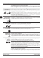
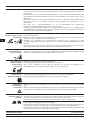
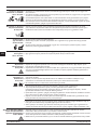
Electric Shocks
May Kill
SAFETY PRECAUTIONS

EN
6
www.magmaweld.comUSER MANUAL
monoCUT 45ix / monoCUT 45iSafety Precautions
• Turn off the electric power.
or wires.
• Call for emergency services.
• If the victim is not breathing, Administer cardiopulmonary resuscitation (CPR) immediately
after breaking contact with the electrical source. Continue CPR (cardiac massage) until
breathing starts or until help arrives.
• Treat an electrical burn as a thermal burn by applying sterile, cold (iced) compresses. Prevent
contamination, and cover with a clean, dry dressing.
Procedures for
Electric Shock
Long-term inhalation of fumes and gases released from welding / cutting is very dangerous.
• Keep away from the moving parts.
closed and in locked position.
• Wear metal toe shoes against the possibility of heavy objects falling on to your feet.
• Burning sensations and irritations in the eyes, nose and throat are signs of inadequate
ventilation. In such a case, immediately boost the ventilation of the work area, and if the
problem persists, stop the welding / cutting process completely.
• Use a suitable fume extraction system where welding / cutting works are being carried out. If
necessary, install a system that can expel fumes and gases accumulated in the entire workshop.
cadmium, zinc, coated or painted materials, use masks that provide fresh air in addition to the
above precautions.
• If the gas tanks are grouped in a separate zone, ensure that they are well ventilated, keep the
main valves closed when gas cylinders are not in use, pay attention to possible gas leaks.
• Shielding gases such as argon are denser than air and can be inhaled instead of air if used in
• Do not perform welding / cutting operations in the presence of chlorinated hydrocarbon vapors
released during lubrication or painting operations.
• Some welded / cut parts require special ventilation. The safety rules of products that require
special ventilation should be read carefully. A suitable gas mask should be worn when
necessary.
Fumes and Gases
May Be Harmful To
Your Health
Moving Parts May
Cause Injuries
Make sure all connections are tight, clean, and dry.
• Keep cables dry, free of oil and grease, and protected from hot metal and sparks.
• Bare wiring can kill. Check all cables frequently for possible damage. If a damaged or an
uninsulated cable is detected, repair or replace it immediately.
• Insulate work clamp when not connected to workpiece to prevent contact with any metal
object.
• Make sure that the grounding of the power line is properly connected.
• Use AC output ONLY if required for the welding process.
• If AC output is required, use remote output control if present on unit.
Additional safety precautions are required when any of the following electrically hazardous
conditions are present :
• in damp locations or while wearing wet clothing,
• when in cramped positions such as sitting, kneeling, or lying,
• when there is a high risk of unavoidable or accidental contact with the workpiece or ground.
For these conditions, use the following equipment in order presented:
• Semiautomatic DC constant voltage (CV) MIG welding machine,
• DC manual MMA welding machine,

EN
7
www.magmaweld.com USER MANUAL
monoCUT 45ix / monoCUT 45i Safety Precautions
• Performing works such as welding / cutting, surface grinding, and brushing cause sparks and
metal particles to splatter. Wear approved protective work goggles which have edge guards
under the welding masks to prevent sustaining possible injuries.
Sparks and Spattering
Particles May Get
Into Eyes and Cause
Damage
• Do not touch the hot parts with bare hands.
• Wait until the time required for the machine to cool down before working on its parts.
Hot Parts May Cause
Severe Burns
• Protect other naked parts of your body (arms, neck, ears, etc.) with suitable protective clothing
from these rays.
so that people around you will not sustain injuries from arc rays and hot metals.
• This machine is not used for heating of icebound pipes. This operation performed with the
Arc Light May Damage
Your Eyes and Skin
• The noise generated by some equipment and operations may damage your hearing ability.
• Wear approved personal ear protective equipment if the noise level is high.
Noise May Cause
Damage To Your
Hearing Ability
• Do not apply welding / cutting operations into completely closed tanks or pipes.
• Before welding to tanks and closed containers, open them, completely empty them, and clean
them. Pay the greatest attention possible to the welding / cutting operations you will perform in
such places.
• Do not weld in tanks and pipes which might have previously contained substances that may
• Welding / cutting equipment heats up. For this reason, do not place it on surfaces that could
easily burn or be damaged !
• Do not point the torch towards any part of the body, other persons, or any metal while
unwrapping the welding / cutting wire.
• When welding wire is run manually from the roller especially in thin diameters the wire can slip
out of your hand, like a spring or can cause damage to you or other people around, therefore you
must protect your eyes and face while working on this.
Welding Wires Can
Cause Injuries
explosions.
• Before starting the welding / cutting work, remove these materials form the environment or cover
• National and international special rules apply in these areas.
Welding Operations
May Cause Fire and
Explosion
extinguishers tubes, water, and sand in easily accessible places.
circuits. Make sure that they are periodically inspected and pay attention that they run reliably.
• Electrical equipment should not be repaired by unauthorized persons.
Errors occurred if failed to do so may result in serious injury or death when using the
equipment.
• The gas circuit elements operate under pressure; explosions may occur as a result of services
provided by unauthorized persons, users may sustain serious injuries.
• It is recommended to perform technical maintenance of the machine and its auxiliary units at
least once a year.
Maintenance Work
Persons To Machines
and Apparatus May
Cause Injuries

EN
8
www.magmaweld.comUSER MANUAL
monoCUT 45ix / monoCUT 45iSafety Precautions
operations, accompanied by another person.
• Avoid performing welding / cutting operations in such enclosed areas as much as possible.
• Take all necessary precautions when moving the machine. The areas where the machine to be
transported, parts to be used in transportation and the physical conditions and health of the
person carrying out the transportation works should be suitable for the transportation process.
• Some machines are extremely heavy; therefore, make sure that the necessary environmental
safety measures are taken when changing their places.
• If the machine is to be used on a platform, it must be checked that this platform has suitable load
bearing limits.
• If it is to be transported by means of a haulage vehicle (transport trolley, forklift etc.), make sure
of the durableness of the vehicle, and the connection points (carrying suspenders, straps, bolts,
nuts, wheels, etc.) that connect the machine to this vehicle.
• If the machine will be carried manually, make sure the durableness of the machine apparatuses
(carrying suspenders, straps, etc.) and connections.
• Observe the International Labor Organization’s rules on carriage weights and the transport
regulations in force in your country in order to ensure the necessary transport conditions.
from torches, cables or hoses. Be absolutely sure to carry gas cylinders separately.
• Remove all interconnections before transporting the welding / cutting equipment, each being
separately, lift and transport small ones using its handles, and the big ones from its handling
rings or by using appropriate haulage equipment, such as forklifts.
Welding / Cutting in
Failure To Take
Precautions During
Transport May Cause
Accidents
way that they would not tip over for sure.
• Allow operators to easily access settings and connections on the machine.
Falling Parts May
Cause Injuries Improper positioning of the power-supply sources or other equipment can cause serious injury
to persons and physical damage to other objects.
• Allow the machine to cool down according to operation cycle rates.
• Reduce the current or operation cycle rate before starting the welding / cutting again.
• Do not block the fronts of air vents of the machines.
Excessive Use Of The
Machine Causes
Overheating
Excessive Use Of The
Machine Causes
Overheating
• This device is in group 2, class A in EMC tests according to TS EN 55011 standard.
• This class A device is not intended for use in residential areas where electrical power is supplied
compatibility due to radio frequency interference transmitted and emitted in such places.
• Make sure that the work area complies with electromagnetic compatibility (EMC).
Electromagnetic interferences during welding / cutting operations may cause undesired effects
on your electronic devices and network; and the effects of these interferences that may occur
during these operations are under the responsibility of the user.
• If there is any interference, to ensure compliance; extra measures may be taken, such as the
use of short cables, use of shielded (armored) cables, transportation of the welding machine to
the work area under protection in terms of EMC.
• To avoid possible EMC damage, make sure to perform your welding / cutting operations as far
away from your sensitive electronic devices as possible (100 m).
connected to the low voltage network used in the home, the installer to make the
electrical connection or the person who will use the machine must be aware that
the machine has been connected in such a manner; in this case the responsibility
belongs to the user.

EN
9
www.magmaweld.com USER MANUAL
monoCUT 45ix / monoCUT 45i Safety Precautions
• Ensure that your welding and/or cutting machine has been installed and situated in its place
according to the user manual.
Before installing the welding / cutting equipment, the person in charge of the operation and / or
the user must conduct an inspection of possible electromagnetic interference in the environment.
Aspects indicated below has to be taken into consideration;
a) Other supply cables, control cables, signal and telephone cables, above and below the welding
/ cutting machine and its equipment,
b) Radio and television transmitters and receivers,
c) Computer and other control hardware,
d) Critical safety equipment, e.g. protection of industrial equipment,
e) Medical apparatus for people in the vicinity, e.g. pacemakers and hearing aids,
f) Equipment used for measuring or calibration,
g) Immunity of other equipment in the environment. The user must ensure that the other
equipment in use in the environment is compatible. This may require additional protection
measures.
h) Considering the time during which the welding / cutting operations or other activities take
place during the day, the boundaries of the investigation area can be expanded according to the
size of the building, the structure of the building and other activities that are being performed
in the building.
• The appliance must be connected to the electricity supply in the recommended manner by a
tube or with an equivalent shielded cable. The housing of the power supply must be connected
and a good electrical contact between these two structures has to be provided.
• The recommended routine maintenance of the appliance must be carried out. All covers on the
body of the machine must be closed and / or locked when the device is in use. Any changes,
other than the standard settings without the written approval of the manufacturer, cannot be
possibly occur.
the work area, in a side by side manner. Welding / cutting cables should not be wound in any
way.
machine to pull metal parts on to itself. To avoid this attraction, make sure that the metal
interconnected metal materials.
• In cases where the workpiece cannot be connected to the ground due to electrical safety, or
because of its size and position (for example, in building marine vessel bodies or in steel
construction manufacturing), a connection between the workpiece and the grounding may
reduce emissions in some cases, it should be kept in mind that grounding of the workpiece may
cause users to sustain injuries or other electrical equipment in the environment to break down.
In cases where necessary, the workpiece and the grounding connection can be made as a direct
connection, but in some countries where direct connection is not permissible, the connection
can be established using appropriate capacity elements in accordance with local regulations
and ordinances.
• Screening and shielding of other devices and cables in the work area can prevent aliasing
applications.
Evaluation Of
Electromagnetic
Suitability Of The
Work Area
Electromagnetic
Interferance
Reduction Methods
(EMF).
All operators must follow the following procedures to minimize the risk of exposure to EMF;
secured as far as possible with the joining materials (tape, cable ties etc.).
• The operator’s body and head should be kept as far away from the welding / cutting machine
and cables as possible,
Electromagnetic Field
(EMF)

EN
10
www.magmaweld.comUSER MANUAL
monoCUT 45ix / monoCUT 45iSafety Precautions
• Choose the welding / cutting method and welding machine for the welding work you are to
perform.
• Select the welding / cutting current and/or voltage to match the material and thickness you are
going to weld.
• If you have to wait for a long time before you start your welding / cutting work, turn off the machine
after the fan has cooled it down. Our machines with smart fan control will turn off on their own.
• This device is not domestic waste. It must be directed to recycling within the framework of the
European Union directive and national laws.
• Obtain information from your dealer and authorized persons about the waste management of
your used machines.
Waste Procedure
(EMF).
All operators must follow the following procedures to minimize the risk of exposure to EMF;
secured as far as possible with the joining materials (tape, cable ties etc.).
• The operator’s body and head should be kept as far away from the welding / cutting machine
and cables as possible,
• Welding / cutting and electric cables should not be wrapped around the body of the machine in
any way,
• The body of the machine should not get caught between the welding / cutting cables. The source
cables must be kept away from the body of the machine, both being placed side by side,
• The return cable must be connected to the workpiece as close as possible to the work area,
• The welding / cutting machine should not rest against the power unit, ensconce on it and not
work too close to it,
• Welding / cutting work should not be performed when carrying the wire supply unit or power
unit.
EMF may also disrupt the operation of medical implants (materials placed inside the body), such
as pacemakers. Protective measures should be taken for people who carry medical implants. For
conducted for welders. Risk assessment should be conducted and recommendations should be
made by a medical professional for users who carry medical implants.
• Do not expose the machine to rain, prevent the machine from splashing water or
pressurized steam.
Protection
WARRANTY FORM
Please visit our website www.magmaweld.com/warranty-form/wr for warranty form.

EN
11
www.magmaweld.com USER MANUAL
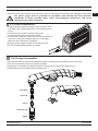
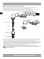
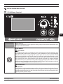
monoCUT 45ix / monoCUT 45i
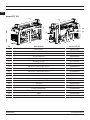
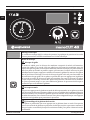
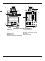
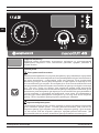
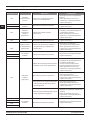
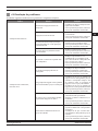
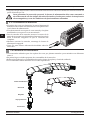
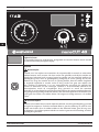
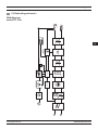
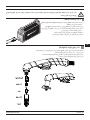
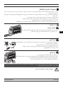
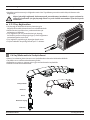
monoCUT 45ix and monoCUT 45i are high performance plasma cutting machines designed for cutting
and gouging applications. With its compact design, it is lightweight and portable. It offers excellent
cutting and gouging performance. In the monoCUT 45ix model, the gas pressure required during cutting
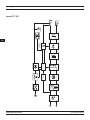
is automatically adjusted according to the cutting mode and the torch used. Whereas, in the monoCUT 45i
model, the required gas pressure must be adjusted manually.
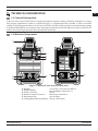
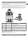
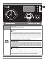
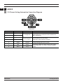
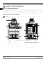
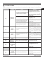
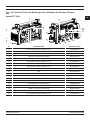
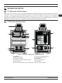
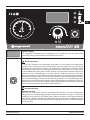
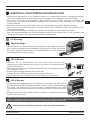
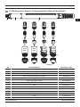
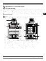
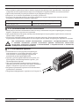
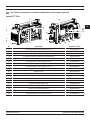
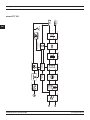
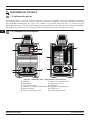
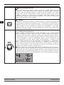
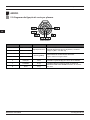
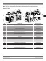
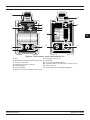
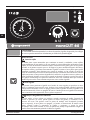
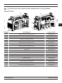
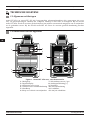
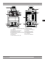
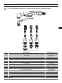
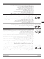
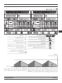
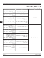
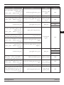
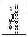
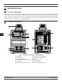
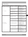
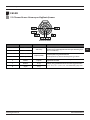
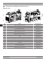
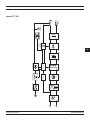
Figure 1 : monoCUT 45ix Front and Back View
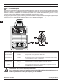
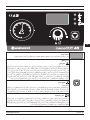
TECHNICAL INFORMATION
1.1 General Information
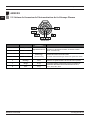
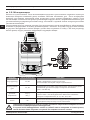
1.2 Machine Components
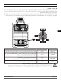
Technical Information
9
10
11
12
1
2
3
4
8
5
7
6
1- Handle
2- Digital Display
3- Torch Connector
4- Remote Control Connector
5- Adjustment Pot
6- Cutting Mode Selection Button
7- Current / Gas Selection Button
8- Grounding Connection (+)
9- Fan
10- Power Connection
11- Air Filter
12- On / Off Switch

EN
12
www.magmaweld.comUSER MANUAL
monoCUT 45ix / monoCUT 45iTechnical Information
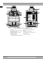
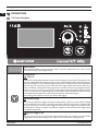
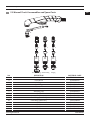
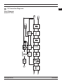
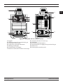
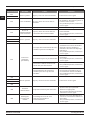
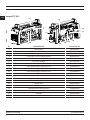
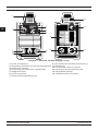
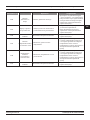
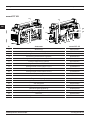
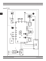
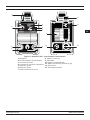
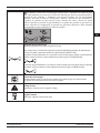
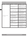
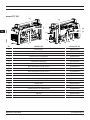
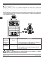
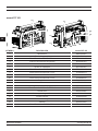
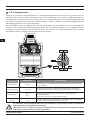
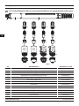
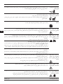
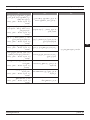
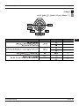
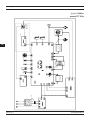
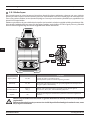
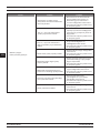
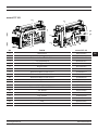
Figure 2 : monoCUT 45i Front and Back View
1- Handle
2- Manual Gas Pressure Display
3- Torch Connector
4- Remote Control Connector
5- Digital Display
6- Adjustment Pot
7- Cutting Mode Selection Button
8- Grounding Connection (+)
9- Fan
10- Power Connection
11- Gas Pressure Adjustment Pot
12- Air Filter
13- On / Off Switch
9
10
12
11
13
1
2
3
4
8
6
7
5

EN
13
www.magmaweld.com USER MANUAL
monoCUT 45ix / monoCUT 45i
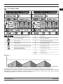
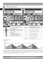
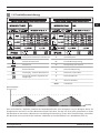
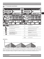
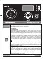
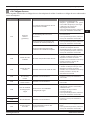
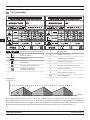
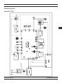
1.3 Product Label
Technical Information
X
U
I
U
U
S
I
Direct Current
Vertical Characteristic
Plasma Cutting
Suitable for Operation at
Hazardous Environments
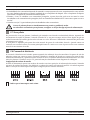
should be kept idle for the machine cool down (zone 2).
Duty Cycle
6 min. 6 min.6 min.4 min. 4 min. 4 min. Time (min.)
Duty Cycle
Open Circuit Voltage
Rated Welding Current
Mains Voltage and Frequency
Protection Class
Rated Welding Voltage
Rated Power
Rated Mains Current
IP23S

EN
14
www.magmaweld.comUSER MANUAL
monoCUT 45ix / monoCUT 45i
1.4 Technical Data
Rated Current
Protection Class
The cutting speeds in the table are the results of Magmaweld’s laboratory tests. It may vary according to different
cutting applications and environmental conditions.
Rated Power
Open Circuit Voltage
Recommended Cutting Thickness
(All metals)
Maximum Cutting Thickness
(All metals)
Breakout Thickness
(All metals)
Gouging
(3,5 mm D x 6,6 mm G)
Weight
Current Range
Dimensions (l x w x h)
1.5 Accessories
Technical Information
STANDARD ACCESSORIES QTY PRODUCT CODE
TECHNICAL DATA UNIT
V
VDC
mm
mm
mm
kg
kVA
ADC
ADC
kg
mm
monoCUT 45ix monoCUT 45i
230 230
45 45
14 14
IP23S IP23S
5,21 5,21
290
3,5 (1 Hour)
290
3,5 (1 Hour)
575 x 160 x 311 575 x 160 x 311
16 (525 mm/sec.)
22 (260 mm/sec.)
30 (130 mm/sec.)
16 (525 mm/sec.)
22 (260 mm/sec.)
30 (130 mm/sec.)
1
1
1
1
1
Workpiece Clamp and Cable
Torch (Hand Cutting)*
Consumable Kit (Hand Cutting)
Consumable Kit (Mechanized Cutting)
Torch (Mechanized Cutting) *
7142H10506
7942000450
7942100450
K301100343
7142M10512

EN
15
www.magmaweld.com USER MANUAL
monoCUT 45ix / monoCUT 45i
INSTALLATION
2.1 Delivery Control
Make sure that all the materials you have ordered have been received. If any material is missing or damaged,
contact your place of purchase immediately.
The standard box includes the following;
• Torch and consumables • User manual
• Workpiece clamp and cable
In case of a damaged delivery, record a report, take a picture of the damage and report to the transport
company together with a photocopy of the delivery note. If the problem persists, contact the customer service.
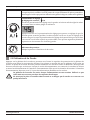
2.2 Installation and Operation Recommendations
Symbols and their meanings on the device
Cutting / welding may be dangerous. Proper working conditions should be ensured and necessary
precautions should be taken. Specialists are responsible for the machine and have to be equipped with the
necessary equipment and those who are not relevant should be kept away from the cutting / welding area.
in homes, it is essential that the installer or the person who will operate the machine to make the electrical
connection has information on the machine’s connectivity. In this case the responsibility will be assumed
by the person who will perform the installation or by the operator.
The safety symbols and warning notes on the device and in the operating instructions must be observed
and the labels must not be removed.
Grids are intended for ventilation. The openings should not be covered in order to provide good cooling and
no foreign objects should be inserted.
• Lifting rings or forklifts should be used to move the machine. Place the power supply on a hard, level, smooth
surface where it will not fall or tip over.
• For a better performance, place the machine at least 30 cm away from the surrounding objects. Pay attention
to overheating, dust and moisture near the machine. Do not operate the machine under direct sunlight. If the
• Avoid cutting outdoors in windy and rainy weather circumstances. If cutting is necessary in such cases,
protect the cutting area and the cutting machine with a curtain and canopy.
• When positioning the machine, make sure that materials such as walls, curtains, boards do not prevent easy
access to the machine’s controls and connections.
• If you cut indoors, use a suitable fume extraction system. Use breathing apparatus if there is a risk of
damage the machine and this may invalidate the warranty.
• The power supply must be grounded in accordance with local and national electrical codes.
the gas cylinder so that it does not tip over.
Installation

EN
16
www.magmaweld.comUSER MANUAL
monoCUT 45ix / monoCUT 45i
2.3 Mains Plug Connection
Never use the mains cable of the machine without a plug for your safety.
Protect the equipment with slow blow fuse appropriate for the system and with an
emergency switch that will quickly shut off the incoming electricity in an emergency.
• Use the appropriate ground cable for your power supply. Push the chassis connector into the connector on the
power supply and snap it in, make sure the connection is tight.
national regulations.
2.4 Connection to Mains
When plugging the power plug into the outlet, make sure that the power switch is set to “0”.
• Before connecting the machine to the mains, check the phase with a voltmeter. After making sure that phase is
correct, insert the plug into the socket.
• Start the machine by using the On/Off switch.
• The machine is ready to start after the MW symbol appears on the screen.
• Turn the machine off by turning the switch back to the “0” position.
2.5 Connections for Plasma Cutting
Be careful during the cutting process and wear appropriate protective clothing and gloves.
2.5.1 Gas Connections
• If the gas source is in the workshop or gas cylinder, a gas regulator should be used and this regulator should be
able to supply gas to the air inlet on the machine.
• If a gas cylinder is used, secure the gas cylinder to prevent it from tipping over.
• In order to work safely and achieve the best results, use a regulator that complies with standards and make sure
the gas supply quality is up to the standards. Gas supply quality will affect cutting performance and
consumption quality.
• Protect the gas line from contaminants such as oil, dust, etc.
• Keep the gas cylinder valve open for a while to allow possible sediment and particles to be discharged.
• Connect the gas regulator to the gas cylinder, make sure that the screw thread on the gas outlet of the gas
cylinder and the nut of the regulator overlap.
• Connect one end of the tube hose to the gas regulator and the other end to the gas inlet at the back of the
machine and open the gas cylinder valve.
• Make sure there are no leaks in the connections.
2.5.2 Grounding Pliers Connections
• Insert the plug of the ground clamp cable into the grounding socket on the machine and tighten it by turning it
to the right. Make sure the connection is made.
be cut.
Gas Source
Cutting : 185 l/min at 5.5 bar.
Gouging : 208 l/min at 4.6 bar.
Installation

EN
17
www.magmaweld.com USER MANUAL
monoCUT 45ix / monoCUT 45i
The power supply must be grounded in accordance with national and local electrical
regulations to ensure personal safety, reduce electromagnetic interference, and create
appropriate operating conditions.
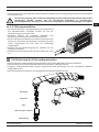
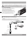
2.5.3 Torch Connections
• Magmaweld brand plasma cutting torches should be used
according to the cutting method to be used with the power
source.
• A manual torch is used for manual cutting, and
a mechanized torch for mechanized cutting.
• For the torch connection, insert the torch connector into its
connector on the power supply and turn it to the right.
Make sure the connection is completed.
• Keep the power supply off while connecting the torch.
• See 5.1 for detailed information on torches.
• The materials used for manual and mechanized plasma cutting torches are different from each other.
• First, the consumables of the torch must be prepared.
• Appropriate consumables should be selected according to the torch type and method used.
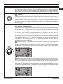
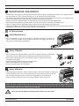
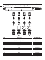
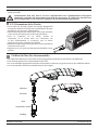
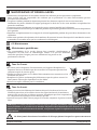
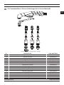
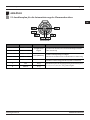
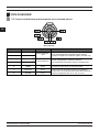
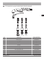
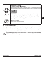
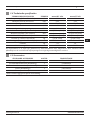
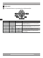
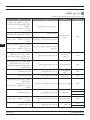
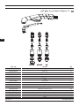
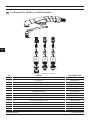
2.6 Placing Consumables
Swirl Ring
Electrode
Nozzle
Retaining Cap
Shield
Installation

EN
18
www.magmaweld.comUSER MANUAL
monoCUT 45ix / monoCUT 45i
• The life of consumables depends on the material to be cut, cutting thickness, cutting length, cutting method,
appropriate distance to the material, air quality and blast frequency. If the frequency of blasting is high, the
consumable will wear out more quickly.
• When working with shielded consumables, the torch tip may touch the metal to be cut while cutting.
torch.
• See 5.1 for detailed information on consumables.
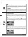
Plasma arc forms immediately when the torch trigger is pressed.
Make sure the power supply is turned off when replacing plasma consumables.
: It shows that the switch is above.
Remote control will only be activated when using a mechanized torch. There is a connector for remote
control at the back of the machine. When the necessary connection is made to the connector on the back
of the power supply, it provides access to the arc voltage and yields a signal for arc transfer and plasma
initiation. See 5.2 for detailed information on automation wiring diagram.
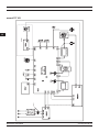
Voltage Divider Setting
Voltage information is changed with the help of the voltage divider. The voltage divider is set to 20:1 as
default. The table below shows the location of the DIP switches for voltage divider settings.
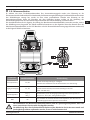
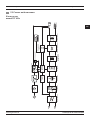
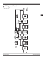
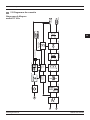
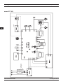
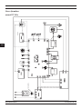
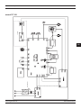
2.8 Remote Control
Ionized gas with high electrical conductivity is used in the plasma cutting process. The moment the plasma
is called pilot arc.
The pilot arc is forced out of the torch tip by high velocity gases. When it comes into contact with the metal
to be cut, the main current is formed and the cutting begins. The cutting process is continued by moving the
torch.
2.7 Pilot Arc
Installation

EN
19
www.magmaweld.com USER MANUAL
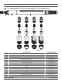
monoCUT 45ix / monoCUT 45i
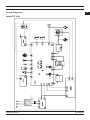
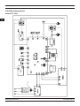
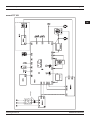
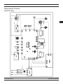
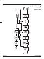
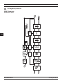
It works with dry contact structure. The automation unit sends a warning to the plasma machine to operate
via the dry contact and the plasma creates a pilot arc. After the plasma machine creates a pilot arc, it sends a
warning to the automation unit with the dry contact structure. When the machine starts the cutting process,
it reports the plasma arc voltage for the automation interface to adjust the height.
The table contains information about the signals. The following table should be observed when the power
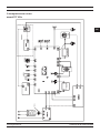
supply is to be connected to the CNC table or torch height controller with the machine interface cable:
Installation of the machine interface cable and voltage divider board assembly should be
When the cover on the interface connector on the back of the machine is not used, it should be
kept closed for keeping out dust and moisture.
Start (Trigger)
Arc Approval
Voltage Divider
Ground
Requires dry contact closure to activate.
Normally open contact. When the plasma arc forms, the contact switches
off. (Max. : 220 VDC 2A)
The machine adapts the output voltage to the control system. It gives
20:1, 21.1:1, 30:1, 40:1, 50:1 divided outputs.
For equipment safety, it is recommended to connect it to the grounding
point of your system.
P1, P3
P7 (+)
P6
P5, P2
Connection
Name Connector Pin Explanation
2.8.1 Communication
Installation

EN
20
www.magmaweld.comUSER MANUAL
monoCUT 45ix / monoCUT 45i
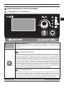
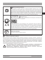
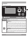
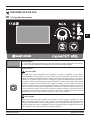
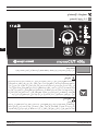
Digital Display
The adjusted welding current, pressure values, pressure graph and error codes can be
monitored visually on the digital screen.
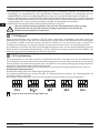
It is used for cutting materials that consist of metal and gaps, such as grids. If this mode is not
used for cutting materials with gaps such as grids, material cutting starts when the pilot arc
after the gap, it is necessary to press and release the trigger again and start the pilot arc in
order to continue cutting. Grid cutting mode was created to be used on grid type materials.
A pilot arc occurs as soon as you press the torch trigger in the grid cutting and the material
is cut. It cuts the pilot arc when the gap is reached, and activates the pilot arc when it arrives
to the material part again. This cycle continues until you release the trigger.
The cutting process ends as soon as you release the trigger.
Pilot arc occurs as soon as you press the trigger in this mode. You can take your hand off the
trigger and continue the cutting process once you have started the cutting process.
Cutting Modes
As soon as you press the trigger in normal cutting mode, a pilot arc occurs and the cutting
arc goes out and you can release the trigger. If you release the trigger in the middle of the
material, the arc will go out again. The pilot arc reappears when you press the trigger again
to continue the process.
Grid Cut
Normal Cutting
Torch Trigger Lock
3.1 User Interface
OPERATION
Operation
A página está carregando...
A página está carregando...
A página está carregando...
A página está carregando...
A página está carregando...
A página está carregando...
A página está carregando...
A página está carregando...
A página está carregando...
A página está carregando...
A página está carregando...
A página está carregando...
A página está carregando...
A página está carregando...
A página está carregando...
A página está carregando...
A página está carregando...
A página está carregando...
A página está carregando...
A página está carregando...
A página está carregando...
A página está carregando...
A página está carregando...
A página está carregando...
A página está carregando...
A página está carregando...
A página está carregando...
A página está carregando...
A página está carregando...
A página está carregando...
A página está carregando...
A página está carregando...
A página está carregando...
A página está carregando...
A página está carregando...
A página está carregando...
A página está carregando...
A página está carregando...
A página está carregando...
A página está carregando...
A página está carregando...
A página está carregando...
A página está carregando...
A página está carregando...
A página está carregando...
A página está carregando...
A página está carregando...
A página está carregando...
A página está carregando...
A página está carregando...
A página está carregando...
A página está carregando...
A página está carregando...
A página está carregando...
A página está carregando...
A página está carregando...
A página está carregando...
A página está carregando...
A página está carregando...
A página está carregando...
A página está carregando...
A página está carregando...
A página está carregando...
A página está carregando...
A página está carregando...
A página está carregando...
A página está carregando...
A página está carregando...
A página está carregando...
A página está carregando...
A página está carregando...
A página está carregando...
A página está carregando...
A página está carregando...
A página está carregando...
A página está carregando...
A página está carregando...
A página está carregando...
A página está carregando...
A página está carregando...
A página está carregando...
A página está carregando...
A página está carregando...
A página está carregando...
A página está carregando...
A página está carregando...
A página está carregando...
A página está carregando...
A página está carregando...
A página está carregando...
A página está carregando...
A página está carregando...
A página está carregando...
A página está carregando...
A página está carregando...
A página está carregando...
A página está carregando...
A página está carregando...
A página está carregando...
A página está carregando...
A página está carregando...
A página está carregando...
A página está carregando...
A página está carregando...
A página está carregando...
A página está carregando...
A página está carregando...
A página está carregando...
A página está carregando...
A página está carregando...
A página está carregando...
A página está carregando...
A página está carregando...
A página está carregando...
A página está carregando...
A página está carregando...
A página está carregando...
A página está carregando...
A página está carregando...
A página está carregando...
A página está carregando...
A página está carregando...
A página está carregando...
A página está carregando...
A página está carregando...
A página está carregando...
A página está carregando...
A página está carregando...
A página está carregando...
A página está carregando...
A página está carregando...
A página está carregando...
A página está carregando...
A página está carregando...
A página está carregando...
A página está carregando...
A página está carregando...
A página está carregando...
A página está carregando...
A página está carregando...
A página está carregando...
A página está carregando...
A página está carregando...
A página está carregando...
A página está carregando...
A página está carregando...
A página está carregando...
A página está carregando...
A página está carregando...
A página está carregando...
A página está carregando...
A página está carregando...
A página está carregando...
A página está carregando...
A página está carregando...
A página está carregando...
A página está carregando...
A página está carregando...
A página está carregando...
A página está carregando...
A página está carregando...
A página está carregando...
A página está carregando...
A página está carregando...
A página está carregando...
A página está carregando...
A página está carregando...
A página está carregando...
A página está carregando...
A página está carregando...
A página está carregando...
A página está carregando...
A página está carregando...
A página está carregando...
A página está carregando...
A página está carregando...
A página está carregando...
A página está carregando...
A página está carregando...
A página está carregando...
A página está carregando...
A página está carregando...
A página está carregando...
A página está carregando...
A página está carregando...
A página está carregando...
A página está carregando...
A página está carregando...
A página está carregando...
A página está carregando...
A página está carregando...
A página está carregando...
A página está carregando...
A página está carregando...
A página está carregando...
A página está carregando...
A página está carregando...
A página está carregando...
A página está carregando...
A página está carregando...
A página está carregando...
A página está carregando...
A página está carregando...
A página está carregando...
A página está carregando...
A página está carregando...
A página está carregando...
A página está carregando...
A página está carregando...
A página está carregando...
A página está carregando...
A página está carregando...
A página está carregando...
A página está carregando...
A página está carregando...
A página está carregando...
A página está carregando...
A página está carregando...
A página está carregando...
A página está carregando...
A página está carregando...
A página está carregando...
A página está carregando...
A página está carregando...
A página está carregando...
A página está carregando...
A página está carregando...
A página está carregando...
A página está carregando...
A página está carregando...
A página está carregando...
A página está carregando...
A página está carregando...
A página está carregando...
A página está carregando...
A página está carregando...
A página está carregando...
A página está carregando...
A página está carregando...
A página está carregando...
A página está carregando...
A página está carregando...
A página está carregando...
A página está carregando...
A página está carregando...
A página está carregando...
A página está carregando...
A página está carregando...
A página está carregando...
A página está carregando...
A página está carregando...
A página está carregando...
A página está carregando...
A página está carregando...
A página está carregando...
A página está carregando...
A página está carregando...
A página está carregando...
A página está carregando...
A página está carregando...
A página está carregando...
A página está carregando...
A página está carregando...
A página está carregando...
A página está carregando...
A página está carregando...
A página está carregando...
A página está carregando...
A página está carregando...
A página está carregando...
A página está carregando...
A página está carregando...
A página está carregando...
A página está carregando...
A página está carregando...
A página está carregando...
A página está carregando...
A página está carregando...
A página está carregando...
A página está carregando...
A página está carregando...
A página está carregando...
A página está carregando...
A página está carregando...
A página está carregando...
A página está carregando...
A página está carregando...
A página está carregando...
A página está carregando...
A página está carregando...
A página está carregando...
A página está carregando...
A página está carregando...
A página está carregando...
A página está carregando...
A página está carregando...
A página está carregando...
A página está carregando...
A página está carregando...
A página está carregando...
A página está carregando...
A página está carregando...
A página está carregando...
A página está carregando...
A página está carregando...
A página está carregando...
A página está carregando...
A página está carregando...
A página está carregando...
A página está carregando...
A página está carregando...
A página está carregando...
A página está carregando...
A página está carregando...
A página está carregando...
A página está carregando...
A página está carregando...
A página está carregando...
A página está carregando...
A página está carregando...
A página está carregando...
A página está carregando...
A página está carregando...
A página está carregando...
A página está carregando...
A página está carregando...
A página está carregando...
A página está carregando...
A página está carregando...
A página está carregando...
A página está carregando...
A página está carregando...
-
 1
1
-
 2
2
-
 3
3
-
 4
4
-
 5
5
-
 6
6
-
 7
7
-
 8
8
-
 9
9
-
 10
10
-
 11
11
-
 12
12
-
 13
13
-
 14
14
-
 15
15
-
 16
16
-
 17
17
-
 18
18
-
 19
19
-
 20
20
-
 21
21
-
 22
22
-
 23
23
-
 24
24
-
 25
25
-
 26
26
-
 27
27
-
 28
28
-
 29
29
-
 30
30
-
 31
31
-
 32
32
-
 33
33
-
 34
34
-
 35
35
-
 36
36
-
 37
37
-
 38
38
-
 39
39
-
 40
40
-
 41
41
-
 42
42
-
 43
43
-
 44
44
-
 45
45
-
 46
46
-
 47
47
-
 48
48
-
 49
49
-
 50
50
-
 51
51
-
 52
52
-
 53
53
-
 54
54
-
 55
55
-
 56
56
-
 57
57
-
 58
58
-
 59
59
-
 60
60
-
 61
61
-
 62
62
-
 63
63
-
 64
64
-
 65
65
-
 66
66
-
 67
67
-
 68
68
-
 69
69
-
 70
70
-
 71
71
-
 72
72
-
 73
73
-
 74
74
-
 75
75
-
 76
76
-
 77
77
-
 78
78
-
 79
79
-
 80
80
-
 81
81
-
 82
82
-
 83
83
-
 84
84
-
 85
85
-
 86
86
-
 87
87
-
 88
88
-
 89
89
-
 90
90
-
 91
91
-
 92
92
-
 93
93
-
 94
94
-
 95
95
-
 96
96
-
 97
97
-
 98
98
-
 99
99
-
 100
100
-
 101
101
-
 102
102
-
 103
103
-
 104
104
-
 105
105
-
 106
106
-
 107
107
-
 108
108
-
 109
109
-
 110
110
-
 111
111
-
 112
112
-
 113
113
-
 114
114
-
 115
115
-
 116
116
-
 117
117
-
 118
118
-
 119
119
-
 120
120
-
 121
121
-
 122
122
-
 123
123
-
 124
124
-
 125
125
-
 126
126
-
 127
127
-
 128
128
-
 129
129
-
 130
130
-
 131
131
-
 132
132
-
 133
133
-
 134
134
-
 135
135
-
 136
136
-
 137
137
-
 138
138
-
 139
139
-
 140
140
-
 141
141
-
 142
142
-
 143
143
-
 144
144
-
 145
145
-
 146
146
-
 147
147
-
 148
148
-
 149
149
-
 150
150
-
 151
151
-
 152
152
-
 153
153
-
 154
154
-
 155
155
-
 156
156
-
 157
157
-
 158
158
-
 159
159
-
 160
160
-
 161
161
-
 162
162
-
 163
163
-
 164
164
-
 165
165
-
 166
166
-
 167
167
-
 168
168
-
 169
169
-
 170
170
-
 171
171
-
 172
172
-
 173
173
-
 174
174
-
 175
175
-
 176
176
-
 177
177
-
 178
178
-
 179
179
-
 180
180
-
 181
181
-
 182
182
-
 183
183
-
 184
184
-
 185
185
-
 186
186
-
 187
187
-
 188
188
-
 189
189
-
 190
190
-
 191
191
-
 192
192
-
 193
193
-
 194
194
-
 195
195
-
 196
196
-
 197
197
-
 198
198
-
 199
199
-
 200
200
-
 201
201
-
 202
202
-
 203
203
-
 204
204
-
 205
205
-
 206
206
-
 207
207
-
 208
208
-
 209
209
-
 210
210
-
 211
211
-
 212
212
-
 213
213
-
 214
214
-
 215
215
-
 216
216
-
 217
217
-
 218
218
-
 219
219
-
 220
220
-
 221
221
-
 222
222
-
 223
223
-
 224
224
-
 225
225
-
 226
226
-
 227
227
-
 228
228
-
 229
229
-
 230
230
-
 231
231
-
 232
232
-
 233
233
-
 234
234
-
 235
235
-
 236
236
-
 237
237
-
 238
238
-
 239
239
-
 240
240
-
 241
241
-
 242
242
-
 243
243
-
 244
244
-
 245
245
-
 246
246
-
 247
247
-
 248
248
-
 249
249
-
 250
250
-
 251
251
-
 252
252
-
 253
253
-
 254
254
-
 255
255
-
 256
256
-
 257
257
-
 258
258
-
 259
259
-
 260
260
-
 261
261
-
 262
262
-
 263
263
-
 264
264
-
 265
265
-
 266
266
-
 267
267
-
 268
268
-
 269
269
-
 270
270
-
 271
271
-
 272
272
-
 273
273
-
 274
274
-
 275
275
-
 276
276
-
 277
277
-
 278
278
-
 279
279
-
 280
280
-
 281
281
-
 282
282
-
 283
283
-
 284
284
-
 285
285
-
 286
286
-
 287
287
-
 288
288
-
 289
289
-
 290
290
-
 291
291
-
 292
292
-
 293
293
-
 294
294
-
 295
295
-
 296
296
-
 297
297
-
 298
298
-
 299
299
-
 300
300
-
 301
301
-
 302
302
-
 303
303
-
 304
304
-
 305
305
-
 306
306
-
 307
307
-
 308
308
-
 309
309
-
 310
310
-
 311
311
-
 312
312
-
 313
313
-
 314
314
-
 315
315
-
 316
316
-
 317
317
-
 318
318
-
 319
319
-
 320
320
-
 321
321
-
 322
322
-
 323
323
-
 324
324
-
 325
325
-
 326
326
-
 327
327
-
 328
328
-
 329
329
-
 330
330
-
 331
331
-
 332
332
-
 333
333
-
 334
334
-
 335
335
-
 336
336
-
 337
337
-
 338
338
-
 339
339
-
 340
340
-
 341
341
-
 342
342
-
 343
343
-
 344
344
-
 345
345
-
 346
346
-
 347
347
-
 348
348
-
 349
349
-
 350
350
-
 351
351
-
 352
352


Magmaweld MONOCUT 45i Plasma Cutting Mechanized Manual do proprietário
- Tipo
- Manual do proprietário
em outras línguas
- español: Magmaweld MONOCUT 45i Plasma Cutting Mechanized El manual del propietario
- français: Magmaweld MONOCUT 45i Plasma Cutting Mechanized Le manuel du propriétaire
- Nederlands: Magmaweld MONOCUT 45i Plasma Cutting Mechanized de handleiding
- Deutsch: Magmaweld MONOCUT 45i Plasma Cutting Mechanized Bedienungsanleitung
- Türkçe: Magmaweld MONOCUT 45i Plasma Cutting Mechanized El kitabı
Artigos relacionados
-
 Magmaweld MONOCUT 45ix Plasma Cutting Handheld Manual do proprietário
-
 Magmaweld ID 65 P Plasma Cutting Handheld Manual do proprietário
-
 Magmaweld ID 500 M ECO Manual do proprietário
-
 Magmaweld ID 300 M PULSE SMART Manual do proprietário
-
 Magmaweld ID 400 MKW PULSE EXPERT Manual do proprietário
-
 Magmaweld ID 400 MKW PULSE SMART Manual do proprietário
-
Magmaweld 523450W210 Compact Expert Series Manual do usuário
-
 Magmaweld ID 300 MK Compact Smart Series Mag Welding Machine Manual do usuário
-
 Magmaweld ID 300 MKW PULSE SMART Manual do proprietário
-
 Magmaweld ID 500 MW PULSE EXPERT Manual do proprietário


