
Instruction Manual
Dry Block Heater, 1 Block, HB1AL
Dry Block Heater, 1 Block, HB1DG
Dry Block Heater, 2 Block, HB2AL
Dry Block Heater, 2 Block, HB2DG
Dry Block Heater, 4 Block, HB4AL
Dry Block Heater, 4 Block, HB4DG
Dry Block Heater, 6 Block, HB6AL
Dry Block Heater, 6 Block, HB6DG
Dry Block Heater, Heat Lid, HB2DGHL
Revision 7
2/14/2020
EN - English ......... 1
FR - Français ......... 16
ES - Español ......... 32
IT - Italiano ......... 48
DE - Deutsch ......... 64
PT - Português ......... 80
NL - Nederlands ......... 96
NO - Norsk ......... 101
DA - Dansk ......... 106
SV - Svenska ......... 111
FI - Suomi ......... 116
HU - Magyar ......... 121
PL - Polski ......... 126
CZ - Czech ......... 131
KR - Korean ......... 135

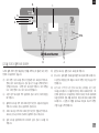
Package contents
Dry Block Heater
Power Cord
Instruction manual
Warranty Card
table of contents
Package Contents . . . . . . . . . . . . . . 1
Service Information . . . . . . . . . . . . . . 1
Installation . . . . . . . . . . . . . . 2
Maintenance & Servicing . . . . . . . . . . . . . . 2
Environmental Conditions . . . . . . . . . . . . . . 2
Equipment Disposal . . . . . . . . . . . . . . 2
Safety Instructions . . . . . . . . . . . . . . 3
Standards & Regulations . . . . . . . . . . . . . . 3
Analog Specifications . . . . . . . . . . . . . . 4-5
Analog Operating Instructions . . . . . . . . . . . . . . 6
Digital Control Panel . . . . . . . . . . . . . . 7
Digital Specifications . . . . . . . . . . . . . . 8-9
Digital Operating Instructions . . . . . . . . . . . . . . 10-14
Troubleshooting . . . . . . . . . . . . . . 15
1
service information
If the troubleshooting section does not resolve or describe your problem, contact your
authorized OHAUS service agent. For service assistance or technical support in the
United States call toll-free 1-800-672-7722 ext. 7852 between 8:00 AM and 5:00 PM EST.
An OHAUS product service specialist will be available to provide assistance. Outside the
USA, please visit our web site, www.ohaus.com to locate the Ohaus office nearest you.
Serial Number: _______________________________________________________
Date of Purchase: ____________________________________________________
Supplier: ___________________________________________________________
EN

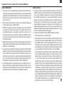
Upon receiving the Ohaus Dry Block Heater, check to ensure that no damage has
occurred in shipment. It is important that any damage that occurred in transport is
detected at the time of unpacking. If you do find such damage the carrier must be
notified immediately.
After unpacking, place the Dry Block Heater on a level bench or table, away from
explosive vapors. Ensure that the surface on which the unit is placed will withstand
typical heat produced by the unit and place the unit a minimum of 6” (15.2cm) from
vertical surfaces. Always place the unit on a sturdy work surface.
The Dry Block Heater is supplied with a power cord that is inserted into the IEC
connector on the back of the unit first, then it can be plugged into a properly grounded
outlet. The 120V unit plugs into a 120 volt, 50/60 Hz source. The 230V unit plugs into
a 230 volt, 50/60 Hz source.
It is necessary to fill the Dry Block Heater well(s) with modular heating blocks because
empty block locations will affect performance. Place filled tubes in modular block(s),
then place the modular block(s) into the Dry Block Heater well(s).
maintenance & servicing
The Dry Block Heater is built for long, trouble-free, dependable service. No lubrication
or other technical user maintenance is required. It needs no user maintenance beyond
keeping the surfaces clean.
The unit should be given the care normally required for any electrical appliance. Avoid
wetting or unnecessary exposure to fumes. Spills should be removed promptly after
the unit has cooled down. DO NOT use a cleaning agent or solvent on the front panel
which is abrasive or harmful to plastics, nor one which is flammable. Always ensure
the power is disconnected from the unit prior to any cleaning. If the unit ever requires
service, contact your Ohaus representative.
The Dry Block Heaters are intended for general laboratory use. Safety cannot be
guaranteed if used outside of the intended use.
environmental conditions
Operating Conditions: Indoor use only.
Temperature: 18 to 33°C (64 to 91°F)
Humidity: 20% to 80% relative humidity, non-condensing
Altitude: 0 to 6,562 ft (2000 M) above sea level
Non-Operating Storage:
Temperature: -20 to 65°C (-4 to 149°F)
Humidity: 20% to 80% relative humidity, non-condensing
Installation Category II and Pollution Degree 2 in accordance with IEC 664.
equiPment disPosal
This equipment must not be disposed of with unsorted waste. It is your
responsibility to correctly dispose of the equipment at life-cycle-end
by handing it over to an authorized facility for separate collection and
recycling. It is also your responsibility to decontaminate the equipment in
case of biological, chemical and/or radiological contamination, so as
to protect the persons involved in the disposal and recycling of the
equipment from health hazards.
For more information about where you can drop off your waste of equipment, please
contact your local dealer from whom you originally purchased this equipment. By doing
so, you will help to conserve natural and environmental resources and you will ensure
that your equipment is recycled in a manner that protects human health.
2
installation intended use
EN

Please read the entire instruction manual before operating the Dry Block Heater.
WARNING! DO NOT use the Dry Block Heater in a hazardous atmosphere
or with hazardous materials for which the unit was not designed. Also, the
user should be aware that the protection provided by the equipment may
be impaired if used with accessories not provided or recommended by the
manufacturer, or used in a manner not specified by the manufacturer.
Always operate unit on a level surface for best performance and
maximum safety.
CAUTION! To avoid electrical shock, completely cut off power to the unit
by disconnecting the power cord from the unit or unplug from the wall outlet.
Disconnect unit from the power supply prior to maintenance and servicing.
Spills should be removed promptly, after the unit has cooled down. DO NOT
immerse the unit for cleaning. DO NOT operate the unit if it shows signs of
electrical or mechanical damage.
The main supply power cord provided with this product is rated to safely
handle the products electrical load under the stated environmental conditions.
DO NOT replace the cord with an inadequately rated main supply cord.
The Dry Block Heaters are designed to be operated in dry conditions. DO
NOT put water, oil or other fluids in the wells of the units. The chamber
that the modular heating blocks and baths sit in is not designed to be filled
with liquid or other fluids. DO NOT place anything other then the appropriate
heating block(s) in this cavity.
CAUTION! Dry Block Heaters are not explosion proof. Use caution when unit
is on or when heating volatile materials.
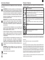
Earth Ground - Protective Conductor Terminal
Alternating Current
3
safety instructions standards & regulations
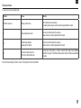
Compliance to the following standards and regulations is indicated by the corresponding mark
on the product.
Mark Standards and Regulations
OHAUS Corporation declares that the HB series dry block heaters comply with direc-
tives 2011/65/EU, 2014/30/EU, 2014/35/EU and standards EN 50581, EN 61010-1,
EN 61010-2-010, EN 61326-1.
The full text of the EU declaration of conformity is available at the following internet
address: www.ohaus.com/ce.
This product complies with directive 2012/19/EU. Please dispose of this product in
accordance with local regulations at the collecting point specified for electrical and
electronic equipment.
For disposal instructions in Europe, refer to www.ohaus.com/weee.
EN 61326-1
CAN/CSA C22.2 61010-1, CAN/CSA C22.2 61010-2-010
UL 61010-1, UL 61010-2-010
Global Notice
Warning: This is a Class A product. In a domestic environment this product may cause radio interfer-
ence in which case the user may be required to take adequate measures.
Canada Notice
This Class A digital apparatus complies with Canadian ICES-003.
FCC Notice
NOTE: This equipment has been tested and found to comply with the limits for a Class A digital
device, pursuant to Part 15 of the FCC Rules. These limits are designed to provide reasonable
protection against harmful interference when the equipment is operated in a commercial envi-
ronment. This equipment generates, uses, and can radiate radio frequency energy and, if not
installed and used in accordance with the instruction manual, may cause harmful interference to
radio communications. Operation of this equipment in a residential area is likely to cause harmful
interference in which case the user will be required to correct the interference at his own expense.
Changes or modifications not expressly approved by Ohaus Corporation could void the user’s authority
to operate the equipment.
EN

4
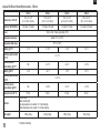
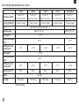
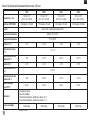
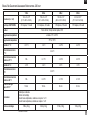
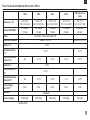
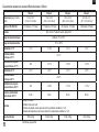
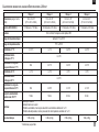
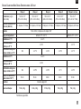
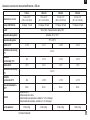
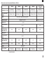
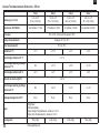
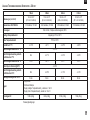
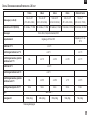
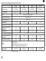
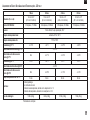
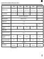
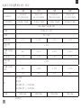
analog dry block Heater sPecifications - 120 volt
1 Block 2 Block 4 Block 6 Block
Dimensions (L x W x H):
12.4 x 8 x 3.5”
(31.5 x 20.3 x 8.9cm)
15.4 x 8 x 3.5”
(39.1 x 20.3 x 8.9cm)
16.9 x 8 x 3.5”
(42.9 x 20.3 x 8.9cm)
20.9 x 8 x 3.5”
(53.1 x 20.3 x 8.9cm)
Electrical 120V 50/60 Hz: 0.92 amps, 110 watts 1.75 amps, 210 watts 2.6 amps, 310 watts 3.42 amps, 410 watts
Fuses: 5mm x 20mm, 5 amp quick acting, 250V
Temperature low range: ambient +5°C to 100°C
Temperature high range: 75°C to 150°C
Stability @ 37°C: +/-1°C +/-1.5°C +/-2°C +/-2°C
Uniformity w/in the block
@ 37°C:
+/-0.1°C
Uniformity across
similar blocks @ 37°C:
N/A +/-0.1°C +/-0.2°C +/-0.3°C
Stability @ 60°C: +/-3°C +/-4°C +/-5°C +/-5°C
Uniformity w/in the block
@ 60°C:
+/-0.6°C
Uniformity across
similar blocks @ 60°C:
N/A +/-0.8°C +/-1.2°C +/-1.4°C
Heat-up time to 100 °C*:
16 min. 16 min. 23 min. 30 min.
Controls:
rocker switch
heat indicator light
low temperature knob, variable 1 to 10 dial markings
high temperature knob, variable 1 to 10 dial markings
Ship weight:
5.8lbs (2.6kg) 6.4lbs (2.9kg) 8.5lbs (3.9kg) 10lbs (4.5kg)
EN
* Conditions Permitting

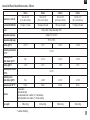
analog dry block Heater sPecifications - 230 volt
5
1 Block 2 Block 4 Block 6 Block
Dimensions (L x W x H):
12.4 x 8 x 3.5”
(31.5 x 20.3 x 8.9cm)
15.4 x 8 x 3.5”
(39.1 x 20.3 x 8.9cm)
16.9 x 8 x 3.5”
(42.9 x 20.3 x 8.9cm)
20.9 x 8 x 3.5”
(53.1 x 20.3 x 8.9cm)
Electrical 230V 50/60 Hz: 0.5 amps, 110 watts 0.92 amps, 210 watts 1.35 amps, 310 watts 1.79 amps, 410 watts
Fuses: 5mm x 20mm, 5 amp quick acting, 250V
Temperature low range: ambient +5°C to 100°C
Temperature high range: 75°C to 150°C
Stability @ 37°C: +/-1.5°C +/-2°C +/-2.5°C +/-2.5°C
Uniformity w/in the block
@ 37°C:
+/-0.4°C
Uniformity across
similar blocks @ 37°C:
N/A +/-0.1°C +/-0.2°C +/-0.3°C
Stability @ 60°C: +/-3°C +/-4°C +/-5°C +/-5°C
Uniformity w/in the block
@ 60°C:
+/-0.6°C
Uniformity across
similar blocks @ 60°C:
N/A +/-0.8°C +/-1.2°C +/-1.4°C
Heat-up time to 100 °C*:
16 min. 16 min. 23 min. 30 min.
Controls:
rocker switch
heat indicator light
low temperature knob, variable 1 to 10 dial markings
high temperature knob, variable 1 to 10 dial markings
Ship weight:
5.8lbs (2.6kg) 6.4lbs (2.9kg) 8.5lbs (3.9kg) 10lbs (4.5kg)
EN
* Conditions Permitting

6
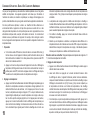
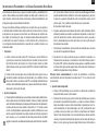
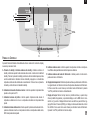
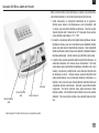
These multi-purpose units are ideal for incubation and activation of cultures, enzyme
reactions, immunoassays, melting/boiling points and a wide variety of other laboratory
procedures.
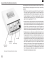
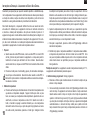
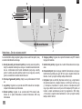
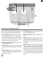
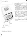
1. Switch the three (3) position rocker power switch from the center off position to
the low range or high range position as desired. The controls are divided into two
separate heating ranges, both thermostats having graduations to assist in setting
the desired temperatures. The left hand ‘low temperature adjust’ controls from
slightly above ambient to approximately 100°C. The right hand ‘high temperature
adjust’ controls from approximately 75°C to 150°C.
2. The rocker switch has a center off position and is used to select the desired operating
range. When operating at the point where the two thermostats overlap in temperature
range, the proper thermostat must be chosen for the task being performed. Move
the power switch to the desired operating range and turn the matching range
temperature control knob clockwise to increase the temperature within the range
selected. The heat indicator light will illuminate during the operation of the heater.
3. The temperature may be verified by placing a calibrated thermometer in the test
solution or by insertion in the modular block thermometer well provided. This hole
fits regular glass bulb thermometers or small diameter digital probes. Due to air
currents and radiation losses, the temperature in the test solution will be lower than
the temperature in the block itself. For the most accurate readings a thermometer
should be placed in a sample test tube with solution matching the samples being
tested. If the temperature is too high or too low, adjust clockwise to increase
temperature, counter-clockwise to decrease temperature. Slight adjustments will
usually suffice to correct the temperature setting. When the heat indicator light
flashes on and off intermittently, check the temperature again. Allow sufficient
time for the temperature to stabilize before re-adjusting. This procedure should be
followed until the desired temperature is reached.
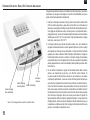
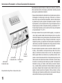
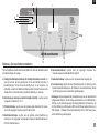
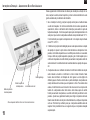
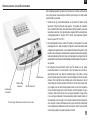
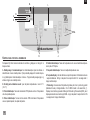
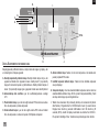
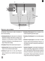
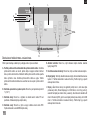
low temperature
adjust knob
high temperature
adjust knob
heat indicator light
rocker switch
Ohaus Analog 1 Block Heater with modular block and tubes
analog dry block Heater oPerating instructions
EN

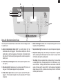
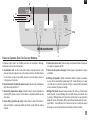
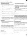
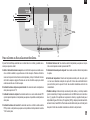
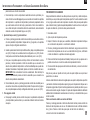
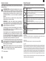
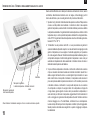
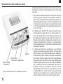
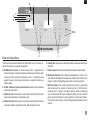
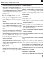
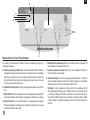
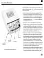
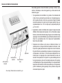
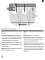
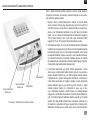
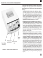
The front panel of the Dry Block Heater contains all the controls and displays needed
to operate the unit.
A. Standby button/standby indicator light: The standby indicator light will
illuminate when the unit is plugged in. The unit will be in standby mode. Press the
standby button to start the temperature and time functions. The standby indicator
light will shut off. Press the standby button again and the unit will once again be in
standby mode.
B. Caution hot top indicator light: Illuminates when the plate temperature is above
40°C (104°F).
C. Plate indicator light: Illuminates when the optional external RTD probe is not
being used. The temperature displayed is the plate temperature.
D. Probe indicator light: Illuminates when the optional external RTD probe is
plugged in. The temperature displayed is the probe temperature, NOT the plate
temperature.
E. Actual indicator light: Illuminates when the temperature displayed is the actual
temperature of the plate/RTD probe.
F. Set-point indicator light: Illuminates when the set-point temperature is displayed.
G. Temperature display: Displays the actual/set-point temperatures in conjunction
with the actual/set-point indicator lights. H. Up/down arrows for set-point control.
On/off button starts/stops the heating function.
I. Time display: Displays accumulated time (continuous mode) or how much time
is remaining (timed mode). The display range is from 0 to 9,999 minutes in one (1)
second increments. The display will indicate minutes and seconds until the timer
reaches 99 minutes and 59 seconds (99:59), then the display will automatically
display minutes up to 9,999. J. Up/down arrows for set-point control. On/off button
starts/stops the timer function.
digital dry block Heater control Panel
E.
A.
J.
H.
F.
D.
C.
I.
G.
B.
7
EN

8
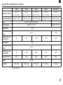
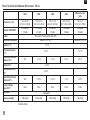
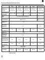
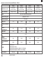
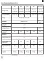
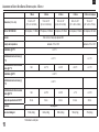
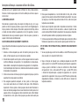
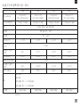
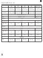
digital dry block Heater sPecifications - 120 volt
1 Block 2 Block 4 Block 6 Block 2 Block with Lid
Dimensions (L x W x H):
12.4 x 8 x 3.5”
(31.5 x 20.3 x 8.9cm)
15.4 x 8 x 3.5”
(39.1 x 20.3 x 8.9cm)
16.9 x 8 x 3.5”
(42.9 x 20.3 x 8.9cm)
20.9 x 8 x 3.5”
(53.1 x 20.3 x 8.9cm)
15.4 x 8 x 7”
(39.1 x 20.3 x 17.8cm)
Electrical 120V 50/60 Hz: 0.92 amps, 110 watts 1.75 amps, 210 watts 2.6 amps, 310 watts 3.42 amps, 410 watts 3.0 amps, 400 watts
Fuses: 5mm x 20mm, 5 amp quick acting, 250V
Temperature range: ambient +5°C to 120°C ambient +5°C to 100°C
Stability @ 37°C: +/-0.1°C
Uniformity w/in the block
@ 37°C:
+/-0.1°C +/-0.1°C
Uniformity across simi-
lar blocks @ 37°C:
N/A +/-0.1°C +/-0.2°C +/-0.3°C +/-0.1°C
Stability @ 60°C: +/-0.4°C
Uniformity w/in the block
@ 60°C:
+/-0.4°C
Uniformity across simi-
lar blocks @ 60°C:
N/A +/-0.5°C +/-0.8°C +/-1°C +/-0.5°C
Heat-up time to 100 °C*:
16 min. 16 min. 23 min. 30 min. 30 min.
Controls:
see page 7
Ship weight:
5.8lbs (2.6kg) 6.4lbs (2.9kg) 8.5lbs (3.9kg) 10lbs (4.5kg) 7lbs (3.2kg)
EN
* Conditions Permitting

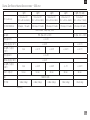
digital dry block Heater sPecifications - 230 volt
9
1 Block 2 Block 4 Block 6 Block 2 Block with Lid
Dimensions (L x W x H):
12.4 x 8 x 3.5”
(31.5 x 20.3 x 8.9cm)
15.4 x 8 x 3.5”
(39.1 x 20.3 x 8.9cm)
16.9 x 8 x 3.5”
(42.9 x 20.3 x 8.9cm)
20.9 x 8 x 3.5”
(53.1 x 20.3 x 8.9cm)
15.4 x 8 x 7”
(39.1 x 20.3 x 17.8cm)
Electrical 230V 50/60 Hz: 0.5 amps, 110 watts 0.92 amps, 210 watts 1.35 amps, 310 watts 1.79 amps, 410 watts 1.65 amps, 400 watts
Fuses: 5mm x 20mm, 5 amp quick acting, 250V
Temperature range: ambient +5°C to 120°C ambient +5°C to 100°C
Stability @ 37°C: +/-0.2°C
Uniformity w/in the block
@ 37°C:
+/-0.2°C +/-0.1°C
Uniformity across simi-
lar blocks @ 37°C:
N/A +/-0.1°C +/-0.2°C +/-0.3°C +/-0.1°C
Stability @ 60°C: +/-0.4°C
Uniformity w/in the block
@ 60°C:
+/-0.4°C
Uniformity across simi-
lar blocks @ 60°C:
N/A +/-0.5°C +/-0.8°C +/-1°C +/-0.5°C
Heat-up time to 100 °C*:
16 min. 16 min. 23 min. 30 min. 30 min.
Controls:
see page 7
Ship weight:
5.8lbs (2.6kg) 6.4lbs (2.9kg) 8.5lbs (3.9kg) 10lbs (4.5kg) 7lbs (3.2kg)
EN
* Conditions Permitting

10
Designed for applications that require repeatable results and superior temperature
stability. These multi-purpose units are ideal for incubation and activation of cultures,
enzyme reactions, immunoassays, melting/boiling points, and a wide variety of other
laboratory procedures.
For best performance, the Dry Block Heater should be used in a stable environment.
The unit’s environment should have no air currents, drafts or temperature changes
and it cannot be placed in direct sunlight. The unit requires a stable electrical supply
that is free of voltage fluctuations. An unstable environment will adversely affect the
performance of the unit. For example, even minor air drafts or temperature changes
will adversely affect the unit’s ability to maintain a stable temperature.
1. Getting ready:
a. When using the external RTD probe, plug the RTD probe into the three (3) pin
DIN connector at the back of the unit and place the thermometer portion in the
thermometer well of the modular block. When using multiple blocks, place the
RTD probe in the front right modular block.
b. Press the standby button to change the unit from standby mode. The
temperature display, time display and probe indicator light will illuminate. When
not using the RTD probe, the plate indicator light will illuminate. The temperature
display will alternate between the actual and set-point temperatures.
2. Setting temperature:
a. Press the up/down arrows to the right of the temperature display until you reach
the desired temperature. Holding down either the up or down arrow will cause
the set temperature to change rapidly, a single pressing of either key will move
the set temperature by 0.1°C. When you release the button, the display will
blink off and then on, indicating the new set temperature has been accepted.
Once the set-point has been programmed and the keys are not being pressed,
press the on/off button to the right of the temperature display to activate the
heating function. A green indicator light will illuminate next to the on/off button
indicating the heating function is on. The actual and set-point indicator lights
will alternate between set and actual temperatures. There are three (3) audible
beeps to indicate the set-point temperature has been reached.
b. Set-point temperature adjustments can be made without interrupting heating
using the up/down arrows to the right of the temperature display. After the
change has been made and you release the button, the display will blink off and
then on indicating the new set temperature has been accepted.
c. To stop heating, press the on/off button to the right of the temperature display.
d. Allow time for the temperature to stabilize. The actual temperature displayed is
the temperature at the bottom of the modular block or of the RTD probe. Once
the displayed actual temperature agrees with the set temperature, several
minutes should be allowed for the temperature to stabilize throughout the block
evenly.
Overshoot protection: If the unit exceeds the set temperature by 10°C, the unit will
automatically stop heating.
3. Setting timed mode: Programmed time.
a. Press the up/down arrows to the right of the time display until you reach the
desired time.
b. Start this function by pressing the on/off button to the right of the time display,
the unit will run for the selected time. When using the timer in conjunction
with the heating function, when the time display reaches zero (0:00), four (4)
audible beeps will indicate the time down function is complete. Both the time
and heating functions will shut off automatically and the time display will default
back to the set time. To repeat for the same time, simply depress the on/off
button again.
c. To interrupt an automatic timing cycle before it is completed, press the on/
off button to the right of the time display. The time display will flash until you
resume the time function by pressing the on/off button again. This interrupt will
not stop the heating function, the heating function will stop only when the timer
reaches zero (0:00).
digital dry block Heater oPerating instructions
EN

4. Setting time to zero (0:00) and continuous mode: Accumulated time.
a. Press and hold the on/off button to the right of the time display. After three (3)
seconds, the display will indicate the previous set time.
b. Simultaneously press both the up and the down arrows, the display will indicate
zero (0:00). The unit time is now set to zero (0:00) minutes. Alternately, you can
use the up/down arrows to get to zero (0:00).
c. Press the on/off button to the right of the time display, the display will indicate
actual running time. The up/down arrows will become inactive. To stop timer,
press the on/off button again. IMPORTANT: This will not affect the heating
function. Press the on/off button to the right of the heat display to interrupt the
heating function.
d. To reset, press and hold the on/off button to the right of the time display. After
three (3) seconds the display will indicate the previous set time, which was zero
(0:00).
5. Turning unit off:
a. To turn the unit off, press the standby button, the temperature and time displays
will be blank, the standby indicator light will turn on.
CALIBRATION PROCEDURE
This procedure is used to fine tune and calibrate the block temperature at a specific
temperature setting. It will only be active without an external temperature probe
connected. This process may be repeated for up to three (3) separate set-points. If
a fourth calibration set-point is entered, the first set-point entered will be overwritten.
1. Turn unit on.
2. Set desired temperature.
3. Stabilize twenty (20) minutes or more, measuring the block temperature with a
calibrated precision instrument or thermometer.
4. Press and hold standby button, then press the temperature up button once. The
unit will beep two (2) times, confirming calibration mode. The display will now be
flashing.
5. Press the temperature up/down arrows until the display matches the temperature
probe/thermometer.
6. Press standby button to exit calibration mode and return to normal heating.
This process may be repeated at the same set-point multiple times for fine tuning if
desired.
The unit will now use the biased offset for that specific temperature setting and
increase or decrease temperature accordingly to bring the block temperature to set
temperature. The decimal point of the display will flash to indicate a biased offset is
being used. All other temperature settings will use the standard internal calibration. This
offset will be stored in memory and retained until reset.
To restore unit to factory setting:
Press and hold standby button while pressing the temperature down button once. The
reset will be confirmed with two (2) beeps. Press the standby button to exit calibration
mode and return to normal heating.
BEEPER PREFERENCE
To silence beeper operation (except for error codes), with the unit in standby mode,
press and hold the time on/off button and press the standby button. To restore
normal beeper operation, remove AC power to unit for 10 seconds and then restore.
Alternately, you may have to turn the unit on and press and hold the standby button
and press and hold the time on/off button simultaneously.
11
EN

12
MODULAR HEATING BLOCKS AND SAMPLES
Only Ohaus Modular Heating Blocks are to be used in the Dry Block Heaters.
1. Select the proper blocks that will be a precise fit for the tubes, plates, or vials that
you will be using for your application.
2. Only plastic or glass tubes, plates, or vials are to be used in the Modular Heating
Blocks. Metal vessels will adversely affect the temperature performance of the unit.
Metal vessels will dissipate too much heat into the air, thus adversely affecting the
temperature readings of the unit.
3. Blocks need to be in all positions on the unit so the heating plate is not exposed to
the environment.
4. To ensure proper heating, the tubes, plates, or vials that are used must be the
correct size for the Modular Heating Block. The tubes, plates or vials must fit
securely in the hole with no air gaps and maintain as much contact as possible with the
wall of the block. This will ensure good thermal contact between the Modular Heating
Block and the tube, plate or vial you are using for your application.
5. For proper heating, the fluid level within your tube, plate or vial should not exceed
the height of the Modular Heating Block. If your application requires the fluid level
to be above the height of the block, then a temperature cover is recommended.
6. When using a temperature measuring device in a sample, the end of the probe
should be placed at the bottom of the sample and the height of the liquid should
not exceed the height of the Modular Heating Block. Ensure that your temperature
measuring device is designed for immersion in liquids.
7. Contact your Ohaus representative for information on ordering Modular Heating
Blocks and other Dry Block Heater accessories.
OPTIONAL EXTERNAL RTD PROBE KIT (FOR DIGITAL UNITS)
1. If your application requires a high level of accuracy, the optional external RTD
probe should be used with the Dry Block Heater.
2. Follow the ‘Operating Instructions’ for the proper installation of the optional
external RTD probe. With the RTD probe plugged into the back of the unit, place
the thermometer portion in the thermometer well of the Modular Heating Block.
With the external RTD probe in place, the RTD probe is now driving the displayed
temperature setting for the operation of the unit, not the heating plate of the unit.
Once the optional external RTD probe is properly installed, the probe indicator LED
above the temperature display will be illuminated.
oPerating instructions cont’d
EN

TEMPERATURE TESTING
1. To ensure good thermal conductivity, select the proper Modular Heating Block
for your application. Select the proper tubes or vials which are the proper size for
the Modular Heating Block. Close contact, with no air gaps, must be maintained
between the walls of the Modular Heating Block well and the sides of the tubes or
vials.
2. Fill the tubes or vials so that the fluid level does not rise above the top surface of
the Modular Heating Block.
3. Select a temperature measuring device that is designed for immersion in liquids.
Place your calibrated temperature measuring device in one of the samples so it
reaches the bottom of the tube or vial. Once the temperature measuring device is
placed in the fluid sample, ensure the fluid level is still below the top surface of the
Modular Heating Block.
4. Set the desired temperature on the unit, allow the unit to reach this temperature,
and let the unit stabilize for an additional twenty (20) minutes or more before taking
any temperature readings.
5. The temperature can also be tested by utilizing the thermometer hole in the Modular
Heating Block. A calibrated temperature measuring device can be inserted into the
thermometer hole where there is a snug fit and close contact between the walls
of the block and the temperature device. The temperature device must reach the
bottom of this hole with no air gaps. Follow the procedure above for allowing the
unit to reach temperature and stabilize before taking any temperature readings.
6. If the measured temperature on your temperature measuring device does not
match the actual temperature on the display of the unit (for Digital units only), then
the single point calibration procedure can be used. By doing this, the unit will now
be more accurate at that set-point for your specific application.
STABILITY TESTING
1. The manufacturer has performed temperature stability tests on Dry Block Heaters.
The manufacturer used calibrated temperature measuring device for the stability
tests. Units were set-up with the proper number of Modular Heating Blocks so
the heater plates were not exposed to the environment. A calibrated temperature
measuring device was inserted into the thermometer well of one block on each
unit. The testing temperature was set, the units were allowed to heat up and
stabilize for a minimum of twenty (20) minutes and then temperature readings
were recorded at regular intervals for four (4) hours. These tests confirmed the
temperature stability of the units.
2. The recommended procedure for testing the unit’s stability is as follows:
a. Set-up the unit in a stable environment.
b. Set-up the unit with the proper number of Modular Heating Blocks for the unit.
Place a calibrated temperature measuring device into the thermometer well of
the Modular Heating Block. The temperature device should have a snug fit with
no air gaps in the thermometer well. Set the temperature of the unit. Allow the
unit to reach temperature and stabilize for twenty (20) minutes or more and then
take temperature readings for stability.
c. Another method to test for stability is to set up the unit with the proper number of
Modular Heating Blocks and then place the proper fitting tubes or vials into the
blocks. Fill the tubes or vials with liquid, where the liquid level is lower than
the top surface of the Modular Heating Block. Use a calibrated temperature
measuring device that is designed for immersion in liquids, and place the
temperature probe in the bottom of one of the tubes or vials in one block. Set
the temperature of the unit. Allow the unit to reach temperature and stabilize for
twenty (20) minutes or more and then take temperature readings for stability.
Please note the characteristics of the liquid used for the test and the fit of the
tube or vial in the Modular Heating Block can affect the results of a stability
test for the Dry Block Heaters. Tubes and vials must be the proper size for the
Modular Heating Block so there is a secure fit with no air gaps to ensure good
thermal contact.
13
EN

14
UNIFORMITY TESTING
1. The manufacturer has performed uniformity tests on Dry Block Heaters to
ensure even heating across the entire heater plate. For the one block heaters,
the manufacturer used a specially designed Modular Heating Block with five (5)
temperature holes. Five independent calibrated temperature measuring devices
were used during the test. For multiple block units, Modular Heating Blocks were
placed in all positions to cover the entire heating plate and then an independent
calibrated temperature measuring device was used in the thermometer well of
each block. For all tests, the tip of the temperature measuring device was an exact
fit for the temperature well in the Modular Heating Block with no air gaps. The
temperature was set and the units were allowed to heat up and stabilize for twenty
(20) minutes or more. Readings were then taken at regular intervals to monitor the
temperature uniformity for four (4) hours. These tests were repeated after rotating
the temperature measuring devices to different thermometer well positions to confirm
the temperature uniformity of the units.
2. The recommended procedure for testing the unit’s temperature uniformity is as
follows:
a. Set-up the unit in a stable environment.
b. Set-up the unit with the proper number of Modular Heating Blocks to cover the
entire heating plate. Then set up the blocks with the proper fitting tubes or vials.
Place liquid samples in tubes or vials where the liquid level is lower than the
height of the top surface of the Modular Heating Block.
c. Select multiple calibrated temperature measuring devices that are designed
for immersion in liquids. Use these temperature measuring devices at the
same time across various positions in the Modular Heating Block(s). Place the
temperature probes in the bottom of several of the filled tubes or vials. Ensure
the liquid levels in the tubes or vials with the temperature probes does not rise
above the height of the top surface of the Modular Heating Block.
d. Set the temperature of the unit. Allow the unit to reach temperature and stabilize
for twenty (20) minutes or more and then take temperature readings from all the
temperature devices to test for temperature uniformity
oPerating instructions cont’d
e. Please note the characteristics of the liquid used for the test and the fit of the
tube or vial in the Modular Heating Block can affect the results of the uniformity
test for the Dry Block Heaters. Tubes and vials must be the proper size for the
Modular Heating Block so there is a secure fit with no air gaps to ensure good
thermal contact.
EN

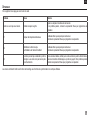
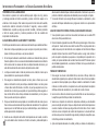
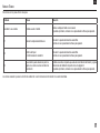
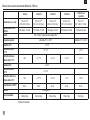
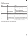
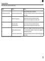
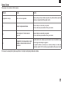
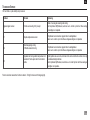
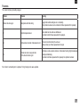
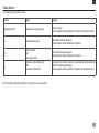
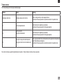
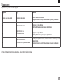
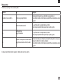
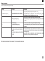
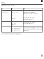
To clear error press the standby button
Problem Cause Solution
Unit fails to power on Missing or blown fuse
Add or replace fuse as necessary.
If problem persists, please contact your Ohaus representative for repair.
E1 Faulty temperature sensor
This error cannot be fixed by the end user.
Please contact your Ohaus representative for repair.
E2
Thermocouple failure or
Heating element failure
This error cannot be fixed by the end user.
Please contact your Ohaus representative for repair.
E3
Unit cannot reach set-point or
Probe not in thermometer well
If using probe, verify probe is in thermo well and follow Single Point Calibration
instructions on page 11. If problem persists, please contact your Ohaus representative
for repair.
Errors will cause heating function to cease. Timing functions will be unaffected.
15
troublesHooting
EN

Manuel d’Instruction
Chauffage à sec, 1 Bloc, HB1AL
Chauffage à sec, 1 Bloc, HB1DG
Chauffage à sec, 2 Blocs, HB2AL
Chauffage à sec, 2 Blocs, HB2DG
Chauffage à sec, 4 Blocs, HB4AL
Chauffage à sec, 4 Blocs, HB4DG
Chauffage à sec, 6 Blocs, HB6AL
Chauffage à sec, 6 Blocs, HB6DG
Chauffage à sec, Bouchon, HB2DGHL
EN - English ......... 1
FR - Français ......... 16
ES - Español ......... 32
IT - Italiano ......... 48
DE - Deutsch ......... 64
PT - Português ......... 80
NL - Nederlands ......... 96
NO - Norsk ......... 101
DA - Dansk ......... 106
SV - Svenska ......... 111
FI - Suomi ......... 116
HU - Magyar ......... 121
PL - Polski ......... 126
CZ - Czech ......... 131
KR - Korean ......... 135

contenu de l’emballage
Bain à sec chauffant
Cordon d’alimentation
Manuel d’instruction
Carte de garantie
table des matiéres
Contenu de l’emballage . . . . . . . . . . . . . . 17
Des informations de service . . . . . . . . . . . . . . 17
Installation . . . . . . . . . . . . . . 18
Maintenance et réparation . . . . . . . . . . . . . . 18
Conditions ambiantes . . . . . . . . . . . . . . 18
Élimination du matériel . . . . . . . . . . . . . . 18
Consignes de sécurité . . . . . . . . . . . . . . 19
Normes et réglementations . . . . . . . . . . . . . . 19
Spécifications - Bain à sec chauffant analogique . . . . . . . . . . . . . 20-21
Consignes d’utilisation - Bain à sec chauffant analogique . . . . . . . . . 22
Panneau de commande numérique . . . . . . . . . . . . . . 23
Spécifications - Bain à sec chauffant numérique . . . . . . . . . . . . . 24-25
Consignes d’utilisation - Bain à sec chauffant numérique. . . . . . . . . 26-30
Dépannage . . . . . . . . . . . . . . 31
17
des informations de service
Si la section de dépannage ne permet pas de résoudre ou ne décrit pas le problème, con-
tacter l’agent d’entretien agréé OHAUS. Pour un service d’assistance ou une prise en charge
technique aux États-Unis, composer le numéro gratuit 1-800-672-7722, poste 7852 entre
8h00 et 17h00 (GMT - 5).
Un spécialiste du service produit OHAUS est disponible pour apporter son aide. En dehors
des États-Unis, bien vouloir se rendre sur notre site web, www.ohaus.com pour rechercher la
filiale OHAUS la plus proche.
Numéro de série: _________________________________________________________
Date d’achat: _____________________________________________________________
Fournisseur: ______________________________________________________________
FR

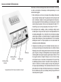
Dès réception du bain à sec chauffant Ohaus, vérifiez qu’il n’a pas été endommagé pen-
dant le transport. Il est important que tout dommage résultant du transport soit détecté lors
du déballage. Informez immédiatement le transporteur en cas de dommage.
Après le déballage, placez le bain à sec chauffant à sec sur un plan de travail ou une table
de niveau, à l’écart de toute vapeur explosive. Assurez-vous que la surface sur laquelle
l’appareil est placé résistera à la chaleur typiquement produite par l’appareil et placez ce
dernier à au moins 15 cm des surfaces verticales. Placez toujours l’appareil sur un plan
de travail solide.
Le bain à sec chauffant est fourni avec un cordon d’alimentation qu’il vous faut tout d’abord
insérer dans le connecteur IEC situé au dos de l’appareil avant de le brancher dans une
prise correctement mise à la terre. L’appareil de 120 V se branche dans une source
d’alimentation de 120 volts, 50/60 Hz. L’appareil de 230 V se branche dans une source
d’alimentation de 230 volts, 50/60 Hz.
Il est nécessaire de remplir le(s) puit(s) du bain à sec chauffant de blocs chauffants modu-
laires car des emplacements de bloc vides affectent les performances. Placez les tubes
pleins dans le(s) bloc(s) modulaire(s) puis posez ce(s) bloc(s) dans les puits du bain à sec
chauffant.
maintenance et réParation
Le bain à sec chauffant est construit pour fonctionner longtemps, de façon efficace et sans
problème. Aucun graissage ou tout autre entretien n’est requis de la part de l’utilisateur.
Le seul entretien nécessaire est de maintenir les surfaces propres. Votre système doit être
traité avec le même soin que n’importe quel autre appareil électrique. Évitez de le mouiller
ou de l’exposer inutilement à des émanations. Les renversements doivent être rapidement
nettoyés une fois que l’appareil s’est refroidi. Pour nettoyer le panneau avant, NE PAS uti-
liser de nettoyant ou de solvant abrasif ou pouvant endommager le plastique, ni de produit
inflammable. Toujours s’assurer que l’alimentation est débranchée avant d’effectuer tout
nettoyage. Si l’appareil doit être réparé, contactez votre représentant Ohaus.
Les plaques chauffantes céramiques sont prévues pour un usage général en
laboratoire. La sécurité ne saurait en cas d’utilisation non prévue.
conditions ambiantes
Conditions de fonctionnement : Pour une utilisation à l’intérieur uniquement.
Températures : 18 à 33 °C (64 to 91°F)
Humidité : 20 à 80 % HR, sans condensation
Altitude : 0 à 6,562 ft (2000 m) au-dessus du niveau de la mer
Stockage :
Températures : -20 à 65 °C (-4 to 149°F)
Humidité : 20 à 80 % HR, sans condensation
Installation de Catégorie II et palier de pollution 2 suivant la norme CEI 664.
élimination du matériel
Ce dispositif ne doit pas être éliminé parmi les déchets non triés. Il est
votre responsabilité d’éliminer de façon appropriée le dispositif à la fin de
son cycle de vie en le confiant à une installation autorisée spécialisée dans
la collecte de déchets tries et le recyclage. Il est aussi votre responsabilité
de décontaminer tout dispositif en cas de contamination biologique, chi-
mique ou radiologique, de façon à protéger les personnes impliquées dans
l’élimination et le recyclage des risques sanitaires.
Pour obtenir plus d’informations concernant les endroits où vos dispositifs peuvent être
déposés pour l’élimination, contactez le concessionnaire auprès duquel vous avez acheté
ce dispositif. En faisant cela, vous contribuerez à conserver des ressources naturelles et
environnementales et vous garantirez que votre dispositif est recyclé d’une manière qui
préserve la santé humaine.
18
installation utilisation Prévue
FR

Veuillez lire le mode d ‘emploi complet avant d’ utiliser le chauffe - eau.
Attention! N’utilisez pas le chauffe-bloc sec dans une atmosphère dangereuse ou
avec des matières dangereuses pour lesquelles l’appareil n’a pas été conçu. De plus,
l’utilisateur doit savoir que la protection fournie par l’équipement peut être altérée si
elle est utilisée avec des accessoires non fournis ou recommandés par le fabricant
ou utilisés d’une manière non spécifiée par le fabricant.
Toujours faire fonctionner l’appareil sur une surface plane pour Sécurité maximale.
Mise en garde! Pour éviter tout risque d’électrocution, coupez complètement
l’alimentation de l’appareil en débranchant le cordon d’alimentation de l’appareil ou
débranchez-le de la prise murale. Débrancher l ‘appareil de l’ alimentation avant de
procéder à l ‘entretien et à l’ entretien.
Les déversements doivent être retirés rapidement, après refroidissement de
l’appareil. Ne pas plonger l’appareil pour le nettoyer. Ne pas faire fonctionner l
‘appareil s’il présente des signes de dommages électriques ou mécaniques.
Le cordon d’alimentation principal fourni avec ce produit est noté pour maintenir
la charge électrique des produits sous des conditions environnementales définies.
EVITEZ de remplacer ce cordon d’alimentation avec un autre cordon d’alimentation
noté différemment.
Les réchauffeurs à blocs secs sont conçus pour être utilisés dans des conditions
sèches. Ne pas mettre d’eau, d’huile ou d’autres fluides dans les puits des unités. La
chambre dans laquelle les blocs de chauffage et les bains modulaires sont installés
n’est pas conçue pour être remplie de liquide ou d’autres fluides. Ne placez rien
d’autre que le (s) bloc (s) chauffant (s) approprié (s) dans cette cavité.
Mise en garde! Les chauffe-blocs secs ne sont pas à l’épreuve des explosions. Soyez
prudent lorsque l’appareil est sous tension ou lorsqu’il chauffe des matières volatiles.
Terre - Borne de protection de conducteur
Courant alternatif
19
consignes de sécurité normes et réglementations
La conformité aux normes et réglementations suivantes est indiquée par la marque correspon-
dante sur le produit.
Marque Normes et Réglementations
OHAUS Corporation déclare que les radiateurs secs série HB sont conformes aux
directives 2011/65 / UE, 2014/30 / EU, 2014/35 / EU et aux normes EN 50581, EN
61010-1, EN 61010-2-010, EN 61326- 1.
Le texte intégral de la déclaration de conformité de l’UE est disponible à l’adresse
Internet suivante: www.ohaus.com/ce.
Ce produit est conforme à la directive 2012/19 / UE. Veuillez jeter ce produit confor-
mément à la réglementation locale au point de collecte spécifié pour les équipements
électriques et électroniques.
Pour obtenir des instructions d’élimination en Europe, consultez www.ohaus.com/
weee.
EN 61326-1
CAN/CSA C22.2 61010-1, CAN/CSA C22.2 61010-2-010
UL 61010-1, UL 61010-2-010
Avis Global
Avertissement: Il s’agit d’un produit de classe A. Dans un environnement domestique, ce produit
peut causer des interférences radio, auquel cas l’utilisateur peut être amené à prendre des mesures
adéquates.
Canada Avis
Cet appareil numérique de classe A est conforme à la norme ICES-003 du Canada.
Avis de la FCC
REMARQUE: Cet équipement a été testé et déclaré conforme aux limites d’un appareil numérique de
classe A, conformément à la partie 15 des règles de la FCC. Ces limites sont conçues pour fournir
une protection raisonnable contre les interférences nuisibles lorsque l’équipement est utilisé dans un
environnement commercial. Cet équipement génère, utilise et peut émettre de l’énergie radiofréquence
et, s’il n’est pas installé et utilisé conformément au manuel d’instructions, peut causer des interférences
nuisibles aux communications radio. Le fonctionnement de cet équipement dans une zone résiden-
tielle est susceptible de causer des interférences nuisibles, auquel cas l’utilisateur devra corriger
l’interférence à ses propres frais.
Les modifications ou modifications non expressément approuvées par Ohaus Corporation peuvent
annuler l’autorisation de l’utilisateur d’utiliser l’équipement.
FR
A página está carregando ...
A página está carregando ...
A página está carregando ...
A página está carregando ...
A página está carregando ...
A página está carregando ...
A página está carregando ...
A página está carregando ...
A página está carregando ...
A página está carregando ...
A página está carregando ...
A página está carregando ...
A página está carregando ...
A página está carregando ...
A página está carregando ...
A página está carregando ...
A página está carregando ...
A página está carregando ...
A página está carregando ...
A página está carregando ...
A página está carregando ...
A página está carregando ...
A página está carregando ...
A página está carregando ...
A página está carregando ...
A página está carregando ...
A página está carregando ...
A página está carregando ...
A página está carregando ...
A página está carregando ...
A página está carregando ...
A página está carregando ...
A página está carregando ...
A página está carregando ...
A página está carregando ...
A página está carregando ...
A página está carregando ...
A página está carregando ...
A página está carregando ...
A página está carregando ...
A página está carregando ...
A página está carregando ...
A página está carregando ...
A página está carregando ...
A página está carregando ...
A página está carregando ...
A página está carregando ...
A página está carregando ...
A página está carregando ...
A página está carregando ...
A página está carregando ...
A página está carregando ...
A página está carregando ...
A página está carregando ...
A página está carregando ...
A página está carregando ...
A página está carregando ...
A página está carregando ...
A página está carregando ...
A página está carregando ...
A página está carregando ...
A página está carregando ...
A página está carregando ...
A página está carregando ...
A página está carregando ...
A página está carregando ...
A página está carregando ...
A página está carregando ...
A página está carregando ...
A página está carregando ...
A página está carregando ...
A página está carregando ...
A página está carregando ...
A página está carregando ...
A página está carregando ...
A página está carregando ...
A página está carregando ...
A página está carregando ...
A página está carregando ...
A página está carregando ...
A página está carregando ...
A página está carregando ...
A página está carregando ...
A página está carregando ...
A página está carregando ...
A página está carregando ...
A página está carregando ...
A página está carregando ...
A página está carregando ...
A página está carregando ...
A página está carregando ...
A página está carregando ...
A página está carregando ...
A página está carregando ...
A página está carregando ...
A página está carregando ...
A página está carregando ...
A página está carregando ...
A página está carregando ...
A página está carregando ...
A página está carregando ...
A página está carregando ...
A página está carregando ...
A página está carregando ...
A página está carregando ...
A página está carregando ...
A página está carregando ...
A página está carregando ...
A página está carregando ...
A página está carregando ...
A página está carregando ...
A página está carregando ...
A página está carregando ...
A página está carregando ...
A página está carregando ...
A página está carregando ...
A página está carregando ...
A página está carregando ...
A página está carregando ...
A página está carregando ...
A página está carregando ...
A página está carregando ...
A página está carregando ...
A página está carregando ...
A página está carregando ...
A página está carregando ...
A página está carregando ...
A página está carregando ...
A página está carregando ...
A página está carregando ...
A página está carregando ...
A página está carregando ...
-
 1
1
-
 2
2
-
 3
3
-
 4
4
-
 5
5
-
 6
6
-
 7
7
-
 8
8
-
 9
9
-
 10
10
-
 11
11
-
 12
12
-
 13
13
-
 14
14
-
 15
15
-
 16
16
-
 17
17
-
 18
18
-
 19
19
-
 20
20
-
 21
21
-
 22
22
-
 23
23
-
 24
24
-
 25
25
-
 26
26
-
 27
27
-
 28
28
-
 29
29
-
 30
30
-
 31
31
-
 32
32
-
 33
33
-
 34
34
-
 35
35
-
 36
36
-
 37
37
-
 38
38
-
 39
39
-
 40
40
-
 41
41
-
 42
42
-
 43
43
-
 44
44
-
 45
45
-
 46
46
-
 47
47
-
 48
48
-
 49
49
-
 50
50
-
 51
51
-
 52
52
-
 53
53
-
 54
54
-
 55
55
-
 56
56
-
 57
57
-
 58
58
-
 59
59
-
 60
60
-
 61
61
-
 62
62
-
 63
63
-
 64
64
-
 65
65
-
 66
66
-
 67
67
-
 68
68
-
 69
69
-
 70
70
-
 71
71
-
 72
72
-
 73
73
-
 74
74
-
 75
75
-
 76
76
-
 77
77
-
 78
78
-
 79
79
-
 80
80
-
 81
81
-
 82
82
-
 83
83
-
 84
84
-
 85
85
-
 86
86
-
 87
87
-
 88
88
-
 89
89
-
 90
90
-
 91
91
-
 92
92
-
 93
93
-
 94
94
-
 95
95
-
 96
96
-
 97
97
-
 98
98
-
 99
99
-
 100
100
-
 101
101
-
 102
102
-
 103
103
-
 104
104
-
 105
105
-
 106
106
-
 107
107
-
 108
108
-
 109
109
-
 110
110
-
 111
111
-
 112
112
-
 113
113
-
 114
114
-
 115
115
-
 116
116
-
 117
117
-
 118
118
-
 119
119
-
 120
120
-
 121
121
-
 122
122
-
 123
123
-
 124
124
-
 125
125
-
 126
126
-
 127
127
-
 128
128
-
 129
129
-
 130
130
-
 131
131
-
 132
132
-
 133
133
-
 134
134
-
 135
135
-
 136
136
-
 137
137
-
 138
138
-
 139
139
-
 140
140
-
 141
141
-
 142
142
-
 143
143
-
 144
144
-
 145
145
-
 146
146
-
 147
147
-
 148
148
-
 149
149
-
 150
150
-
 151
151
-
 152
152


em outros idiomas
- español: Ohaus HB2DGHL Manual de usuario
- français: Ohaus HB2DGHL Manuel utilisateur
- italiano: Ohaus HB2DGHL Manuale utente
- English: Ohaus HB2DGHL User manual
- Deutsch: Ohaus HB2DGHL Benutzerhandbuch
Artigos relacionados
-
Ohaus e-G71HS07C Manual do usuário
-
Ohaus VXMTAL Manual do usuário
-
Chemglass CG-9506-01 Guia rápido
-
-
-
-
-
-