
Dell Inc. Telephone: 512.338.4400
One Dell Way Telefax: 512.728.3653
Round Rock, TX78682
DELL CONFIDENTIAL Page 1
Date: Nov 07, 2016
Subject: Statement of Volatility – Dell OptiPlex 5050_MT
To whom it may concern:
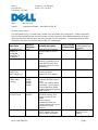
The Dell OptiPlex 5055_MT contains both “volatile” and “non-volatile” (NV) components. Volatile components
lose their data immediately upon removal of power from the component. Non-volatile components continue to
retain their data even after the power has been removed from the component. The following volatile and NV
components are present on the Dell OptiPlex 5055_MT motherboard:
Description
Reference
Designator
Volatility Description
User Accessible
for external data
Remedial Action
(action necessary to
lose data)
Embedded Flash
memory in
embedded
controller ITE
IT8669E/IX
U707
2K bytes of on-chip ROM
and 242 bytes of on-chip
RAM
No
N/A
System BIOS
SPI_1
16M bytes non-volatile
memory, system BIOS and
video BIOS for basic boot
operation, ePSA (on board
diagnostics.)
No
N/A
TPM
NUVOTON
NPCT650JBCYX
UF1
16K bytes non-volatile
memory located in
NUVOTON TPM module.
No
N/A
System Memory –
DDR4 DIMM
memory
Connectons:
DIMM1,
DIMM2,
DIMM3,
DIMM4.
Volatile memory in off state
(see state definitions later in
text)
One to four modules will be
populated. System memory
size will depend on DIMM
modules and will be between
4GB to 64GB.
Yes
Power off system.
System memory
SPD EEPROM
On memory
DIMM(s)
256 bytes non-volatile
EEPROM memory. One
Device present on each
DIMM.
Stores memory
manufacturer data and
timing information for correct
operation of system
memory.
No
N/A
RTC CMOS
RTC_CR2032
Volatile battery back-backed
CMOS memory 256 bytes.
Stores CMOS information.
No
Removing the on
board Coin Cell
battery.

DELL CONFIDENTIAL Page 2
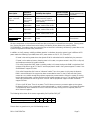
Description
Reference
Designator
Volatility Description
User Accessible
for external data
Remedial Action
(action necessary to
lose data)
Video memory –
type – see next
column
UMA
architecture-
uses system
memory.
Volatile memory in off state.
UMA uses main system
memory size allocated out of
main memory.
No
Enter S3-S5 state
below.
SD Memory Card
User
replaceable
Non-volatile magnetic
media, various sizes in GB.
Yes
Low level format.
M.2 Solid State
Disk
User
replaceable
Non-volatile magnetic
media, various sizes in GB.
Yes
Low level format.
Hard Disk Drives
User
replaceable
Non-volatile magnetic
media, various sizes in GB.
Yes
Low level format.
CD-ROM/RW/ DVD/
DVD+RW/ Disk
Drives
User
replaceable
Non-volatile optical/magnetic
media.
Yes
Low level
format/erase.
All other components on the motherboard will lose data once power is removed from the system. Primary power
loss (Unplug the power cord and remove the battery) will destroy all user data on the memory (DDR4,
2133/2400MHz). Secondary power loss (removing the on board coin cell battery) will destroy system data on the
system configuration and time-of-day information.
In addition, to clarify memory volatility and data retention in situations where the system is put in different ACPI
power states the following is provided (those ACPI power states are S0, S1, S3, S4 and S5):
S0 state is the working state where the dynamic RAM is maintained and is read/write by the processor.
S1 state is a low wake-up latency sleeping state. In this state, no system context is lost (CPU or chip set)
and hardware maintains all system contexts.
S3 is called “suspend to RAM” state or stand-by mode. In this state the dynamic RAM is maintained. Dell
systems will be able to go to S3 if the OS and the peripherals used in the system supports S3 state. Linux
and Windows7 support S3 state.
S4 is called “suspend to disk” state or “hibernate” mode. There is no power. In this state, the dynamic
RAM is not maintained. If the system has been commanded to enter S4, the OS will write the system
context to a non-volatile storage file and leave appropriate context markers. When the system is coming
back to the working state, a restore file from the non-volatile storage can occur. The restore file has to be
valid. Dell systems will be able to go to S4 if the OS and the peripherals support S4 state. Windows 7
support S4 state.
S5 is the “soft” off state. There is no power. The OS does not save any context to wake up the system.
No data will remain in any component on the system board, i.e. cache or memory. The system will require
a complete boot when awakened. Since S5 is the shut off state, coming out of S5 requires power on
which clears all registers.
The following table shows all the states supported by Dell OptiPlex 5050_MT
Model Number
S0
S1
S3
S4
S5
Dell OptiPlex 5055_MT
X
X
X
X
Please direct any questions to your Dell Marketing contact.

DELL CONFIDENTIAL Page 3
Sincerely,
Dell Marketing
-
 1
1
-
 2
2
-
 3
3


