SICK PLG3 Instruções de operação
- Categoria
- Brinquedos
- Tipo
- Instruções de operação

ENGLISHENGLISH
Photoelectric light grid
with visible redlight
Operating instruction
Safety notes
>Read the operating instructions before starting operation.
>Connection, assembly, and settings only by competent technicians.
>Protect the device against moisture and soiling when operating.
>No safety component in accordance with EU machine guidelines.
Correct use
The PLG3 photoelectric light grid is an optoelectronic sensor and is used for
optical, non-contact detection of objects, animals, and people. Reective
tape on the back of the subsequent sensor replaces the reector; a reector
is only required at the end of the series as termination. The integrated job
LED signals the withdrawal bin.
Starting operation
1 Light/dark switching conguration and job LED:
Switch 1 (ex-works setting: D):
D: dark-switching, output (Q) switches if light is interrupted.
L: light-switching: output (Q) switches if the light path is uninterrupted.
Switch 2 (ex-works setting: Steady):
Steady: Job LED lights continuously
Flash: Job LED blinks (3/s).
Connect and secure cable receptacle tension-free.
One output for all optical components.
Obstruction of one or more light beams: output active.
Only for versions with connecting cable:
The following apply for connection in B: brn=brown, blu=blue,
blk=black, wht=white.
Connect cables.
2 Installation
Install the sensor using two M5 Allen head screws and matching
sliding blocks ush externally on parallel aluminum sections or shelf
edges.
Pay attention to the range (see the specications). If the range is more
than 1 m: use reector type PL150 or PL180E01.
Align the sensor(s) to the back of the reector of the subsequent
sensor. Use a reector (see accessories) at the end of the row (instead
of a sensor).
Screw the M5 Allen head screws tight.
Connect sensor to operating voltage (see type label):
The green POWER ON LED must light.
3 Alignment of light received:
When there is optimal light reception, the LED lights continuously
(in front and above). If it does not light or blinks, no light or too little
light is being received. Realign or clean the sensor and the reector.
4 Check hand detection:
Place your hand in the light beam; the signal strength indicator must
switch o. It must light again after you remove your hand.
5 Connection Job LED:
Connect input “Job-LED” (Pin 2) with VS:
Green 360° Job LED lights up or blinks (3/s) (Switch 2: Flash).
Job LED and output Q are not galvanically separated.
Maintenance
SICK sensors are maintenance-free.
We recommend doing the following regularly:
– Clean the external lens surfaces
– Check the screw connections and plug-in connections
No modications may be made to devices.
Subject to change without notice. Specied product properties and tech-
nical data are not written guarantees.
DEUTSCHDEUTSCH
Reexions-Lichtgitter
mit sichtbarem Rotlicht
Betriebsanleitung
Sicherheitshinweise
>Vor der Inbetriebnahme die Betriebsanleitung lesen.
>Anschluss, Montage und Einstellung nur durch Fachpersonal.
>Gerät bei Inbetriebnahme vor Feuchte und Verunreinigung schützen.
>Kein Sicherheitsbauteil gemäß EU-Maschinenrichtlinie.
Bestimmungsgemäße Verwendung
Das Reexions-Lichtgitter PLG3 ist ein optoelektronischer Sensor und wird
zum optischen, berührungslosen Erfassen von Objekten, Tieren und Perso-
nen eingesetzt. Eine Reexfolie auf der Rückseite des folgenden Sensors
ersetzt den Reektor; nur am Ende der Reihe ist ein Reektor als Abschluss
erforderlich. Die integrierte Job-LED signalisiert das Entnahmefach.
Inbetriebnahme
1 Konguration Hell-/Dunkelschaltung und Job-LED:
Schalter 1 (Werksauslieferung: D):
D: dunkelschaltend, bei Lichtunterbrechung schaltet Ausgang (Q).
L: hellschaltend: bei Lichtweg frei schaltet Ausgang (Q).
Schalter 2 (Werksauslieferung: Steady):
Steady: Job-LED leuchtet permanent
Flash: Job-LED blinkt (3/s).
Leitungsdose spannungsfrei aufstecken und festschrauben.
Ein gemeinsamer Ausgang für alle optischen Komponenten.
Unterbrechung eines oder mehrerer Lichtstrahlen: Ausgang aktiv.
Nur für Varianten mit Anschlussleitung:
Für Anschluss in B gilt: brn=braun, blu=blau, blk=schwarz, wht=weiß.
Leitungen anschließen.
2 Montage
Sensor mit den zwei M5-Imbus-Schrauben und den passenden Nuten-
steinen außen ach auf parallele Aluminium-Prole bzw. Regalkanten
montieren.
Dabei Reichweite beachten (s. Technische Daten). Bei Reichweite über
1 m: Reektor-Typ PL150 oder PL180E01 einsetzen.
More representatives and agencies at www.sick.com ∙ Subject to change
without notice ∙ The specied product features and technical data do not
represent any guarantee.
Weitere Niederlassungen nden Sie unter www.sick.com ∙ Irrtümer
und Änderungen vorbehalten ∙ Angegebene Produkteigenschaften und
technische Daten stellen keine Garantieerklärung dar.
Plus de représentations et d’agences à l’adresse www.sick.com ∙ Sujet à
modication sans préavis ∙ Les caractéristiques de produit et techniques
indiquées ne constituent pas de déclaration de garantie.
Para mais representantes e agências, consulte www.sick.com ∙ Alterações
poderão ser feitas sem prévio aviso ∙ As características do produto e os
dados técnicos apresentados não constituem declaração de garantia.
Altri rappresentanti ed agenzie si trovano su www.sick.com ∙ Contenuti
soggetti a modiche senza preavviso ∙ Le caratteristiche del prodotto e i dati
tecnici non rappresentano una dichiarazione di garanzia.
Más representantes y agencias en www.sick.com ∙ Sujeto a cambio sin
previo aviso ∙ Las características y los datos técnicos especicados no
constituyen ninguna declaración de garantía.
欲了解更多代表机构和代理商信息,请登录 www.sick.com ∙
如有更改 , 不另行通知 ∙ 对所给出的产品特性和技术参数
的正确性不予保证。
その他の営業所は www.sick.com よりご覧ください ∙ 予告なし
に変更されることがあります ∙ 記載されている製品機能およ
び技術データは保証を明示するものではありません。
Другие филиалы и представительства приведены на веб-сайте
www.sick.com ∙ Возможны ошибки и технические изменения ∙
Приведенные характеристики продукта и технические данные
гарантированными не являются.
PLG3
-------------------------------------------------------- 8011481.1EDL 0823 COMAT -----------------------------------------------------
BZ int46
Please find detailed addresses and further locations in all major industrial
nations at www.sick.com
Australia
Phone +61 3 9457 0600
Austria
Phone +43 22 36 62 28 8-0
Belgium/Luxembourg
Phone +32 2 466 55 66
Brazil
Phone +55 11 3215-4900
Canada
Phone +1 905 771 14 44
Czech Republic
Phone +420 2 57 91 18 50
Chile
Phone +56 2 2274 7430
China
Phone +86 20 2882 3600
Denmark
Phone +45 45 82 64 00
Finland
Phone +358-9-2515 800
France
Phone +33 1 64 62 35 00
Germany
Phone +49 211 5301-301
Hong Kong
Phone +852 2153 6300
Hungary
Phone +36 1 371 2680
India
Phone +91 22 4033 8333
Israel
Phone +972 4 6881000
Italy
Phone +39 02 274341
Japan
Phone +81 3 5309 2112
Malaysia
Phone +6 03 8080 7425
Mexico
Phone +52 472 748 9451
Netherlands
Phone +31 30 2044 000
New Zealand
Phone +64 9 415 0459
Norway
Phone +47 67 81 50 00
Poland
Phone +48 22 539 41 00
Romania
Phone +40 356 171 120
Russia
Phone +7 495 775 05 30
Singapore
Phone +65 6744 3732
Slovakia
Phone +421 482 901201
Slovenia
Phone +386 591 788 49
South Africa
Phone +27 11 472 3733
South Korea
Phone +82 2 786 6321
Spain
Phone +34 93 480 31 00
Sweden
Phone +46 10 110 10 00
Switzerland
Phone +41 41 619 29 39
Taiwan
Phone +886 2 2375-6288
Thailand
Phone +66 2645 0009
Turkey
Phone +90 216 528 50 00
United Arab Emirates
Phone +971 4 88 65 878
United Kingdom
Phone +44 1727 831121
USA
Phone +1 800 325 7425
Vietnam
Phone +84 945452999
SICK AG, Erwin-Sick-Strasse 1, DE-79183 Waldkirch
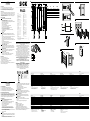
A
PLG3
SR scanning range Reichweite RW Portée RW Alcance da luz RW Portata RW 0.11 m ... 1.3 m (max. 2 m)
Light spot diameter Lichtfleckdurchmesser Diamètre de la tache lumineuse Tamanho do ponto de luz Diametro punto lumioso 80 mm @ 1 m
Supply voltage VSVersorgungsspannung UVTension d‘alimentation UVTensão de força UVTensione di alimentazione UVDC 15 … 30 V 1)
Current consumption sender 2) Stromaufnahme Sender 2) Consommation de courant emetteur 2) Consumo de corrente emissor 2) Corrente assorbita transmittente 2) < 45 mA
Current consumption Job-LED 2) Stromaufnahme Job-LED 2) Consommation de courant LED de travail 2) Consumo de corrente Job-LED 2) Corrente assorbita Job-LED 2) < 10 mA
Output current Imax Ausgangsstrom Imax Courant de sortie Imax Corrente de saída Imax Corrente di uscita Imax 100 mA
Response time Ansprechzeit Temps de réponse Tempo de reação Tempo di risposta < 80 ms
Enclosure rating (IEC 144) Schutzart (IEC 144) Type de protection (IEC 144) Tipo de proteção (IEC 144) Tipo di protenzione (IEC 144) IP 54
VDE protection class VDE-Schutzklasse Classe de protection VDE Classe de proteção VDE Classe di protenzione VDE III
Circuit protection 3) Schutzschaltungen 3) Circuits de protection 3) Circuitos protetores 3) Commutazioni di protezione 3) A, B, C
Ambient operating temperature Betriebsumgebungstemperatur Température ambiante Temperatura ambiente de operação Temperatura ambiente circostante -10 … +55 °C
1) Limits:
Residual ripple max. 5 Vpp
2) Without load
3) A = VS connections reverse polarity protected
B = outputs protected against short circuits
C = interference pulse suppression
1) Grenzwerte:
Restwelligkeit max. 5 VSS
2) Ohne Last
3) A = UV-Anschlüsse verpolsicher
B = Ausgänge kurzschlussfest
C = Störimpulsunterdrückung
1) Valeurs limites:
Ondulation résiduelle max. 5 VSS
2) Sans charge
3) A = Raccordements UV protégés contre les inversions de
polarité
B = Sorties protégées contre les courts-circuits
C = Suppression des impulsions parasites
1) Valores limite:
Ondulação residual máx. 5 VSS
2) Sem carga
3) A = Conexões UV protegidas contra inversão de polos
B = Saí das protegidas contra curto circuito
C = Supressão de impulsos parasitas
1) Valori limite:
Ondulatione residua max. 5 VSS
2) Senza carico
3) A = UV-collegamenti con protez. contro inversione di poli
B = Uscite a prova di corto circuito
C = Soppressione di impulsi di disturbo
PLG3
Alcance RW 大有效感距 RW 検出距離 RW Дальность сканирования RW 0.11 m ... 1.3 m (max. 2 m)
Diámetro de mancha de luz 光点直径 / 距离 光点直径 Диаметр светового пятна 80 mm @ 1 m
Tensión de alimentación UV电源电压 UV供給電圧 UVНапряжение питания, UVDC 15 … 30 V 1)
Corriente absorbida emisor 2) 耗电器 2) 投光器消費電流 2) Потребляемый ток, передатчик 2) < 45 mA
Corriente absorbida Job-LED 2) 耗电 Job-LED 2) Job LEDの消費電流 2) Потребляемый ток, рабочий светодиод 2) < 10 mA
Corriente de salida Imax 输出电流 Imax. 最大出力電流 Imax Выходной ток, Imax 100 mA
Tiempo de reacción 触发时间 応答時間 Время отклика < 80 ms
Tipo de protección (IEC 144) 保护种类 (IEC 144) 保護等級 (IEC 144) Степень защиты (IEC 144) IP 54
Protección clase VDE VDE 保护级别 VDE保護クラス Класс защиты в соответствии со стандартами VDE III
Circuitos de protección 3) 保护电路 3) 保護回路 3) Схемы защиты 3) A, B, C
Temperatura ambiente de servicio 工作环境 - 温度 使用周囲温度 Диапазон рабочих температур -10 … +55 °C
1) Valores lí mite:
Ondulación residual max. 5 VSS
2) Sin carga
3) A = Conexiones UV a prueba de inversión de polaridad
B = Salidas resistentes al cortocircuito
C = Represión de impulso de interferencia
1) 极限值剩余波
纹度 : max. 5 VSS
2) 时无负载
3) A = UV-接头防反接
B = 输出端抗过流 - 及短路
C = 消除, 扇怕沖
1) 限界値:
最大残留リップル 5 VSS
2) 負荷なし
3) A = UVコネクタ 逆極性保護
B = 短絡防止出力
C = 干渉パルス抑制
1) Предельные значения:
остаточная пульсация макс. 5 VSS
2) Без нагрузки
3) A = разъемы для напряжения питания с защитой от
переполюсовки
B = выходы с защитой от короткого замыкания
C = подавление импульсных помех
Sensor(en) jeweils auf die Reektor-Rückseite des folgenden Sensors
ausrichten. Am Ende der Reihe (statt eines Sensors) einen Reektor
(siehe Zubehör) verwenden.
M5-Imbus-Schrauben fest anziehen.
Sensor an Betriebsspannung legen (s. Typenaufdruck):
Grüne POWER ON LED muss leuchten.
3 Justage Lichtempfang:
Bei optimalem Lichtempfang leuchtet die gelbe LED permanent.
Leuchtet sie nicht oder blinkt sie, wird kein oder zuwenig Licht empfan-
gen: Sensor und Reektor neu justieren bzw. reinigen.
4 Kontrolle Handerfassung:
Hand in den Strahlengang bringen; die Empfangsanzeige muss
erlöschen. Nach Entfernen der Hand muss sie wieder aueuchten.
5 Anschluss Job-LED:
Eingang „Job-LED“ (Pin 2) mit UV verbinden:
Grüne 360°-Job-LED leuchtet auf bzw. blinkt mit 3/s bei Schalter 2
auf „Flash“.
Job-LED und Ausgang Q sind nicht galvanisch getrennt.
Wartung
SICK-Sensoren sind wartungsfrei.
Wir empfehlen, in regelmäßigen Abständen
– die optischen Grenzächen zu reinigen
– Verschraubungen und Steckverbindungen zu überprüfen
Veränderungen an Geräten dürfen nicht vorgenommen werden.
Irrtümer und Änderungen vorbehalten. Angegebene Produkteigenschaften
und technische Daten stellen keine Garantieerklärung dar.
A
5
(0.20)
DH
9.5
(0.37)
9.5
(0.37)
23
(0.91)
43 (1.69)
30
(1.18)
L1
16.5
(0.65)
27
(1.06)
RL
Ø 13 (0.51)
19.2
(0.76)
11
(0.43)
Ø 5.3
(0.21)
36.6
(1.44)
D
12
L
Steady
Flash
RLDH AL1
120 (4.72) 36 (1.42) 199.8 (7.87) 162 (6.38)
210 (8.27) 26 (1.02) 279.8 (11.02) 242 (9.53)
270 (10.63) 36 (1.42) 349.8 (13.77) 312
(12.28)
360 (14.17) 26 (1.02) 429.8 (16.92) 392
(15.43)
420 (16.54) 36 (1.42) 499.8 (19.68) 462
(18.19)
1
L+
Q
Job-LED
M
1
4
2
3
brn
blk
wht
blu
B
2a
2b
M5
POWER ON
< 1m
3
5
360°
4

FRANÇAISFRANÇAIS
Barrière lumineuse réex à grille
avec lumière de rouge
Manuel d’utilisations
Remarques relatives à la sécurité
>Lire la notice d’instruction avant la mise en service.
>Installation, raccordement et réglage ne doivent être eectués que par
du personnel qualié.
>Lors de la mise en service, protéger l’appareil de l’humidité et des
saletés.
>N’est pas un composant de sécurité au sens de la directive européenne
concernant les machines.
Utilisation conforme
Le barrage multifaisceaux réex PLG3 est un capteur optoélectronique
qui s’utilise pour la saisie optique de choses, d’animaux ou de personnes
sans aucun contact. Une feuille rééchissante au dos du capteur qui
suit remplace le réecteur; c’est seulement à la n de la série qu’il est
nécessaire d’avoir un réecteur terminal. La LED de travail intégrée indique
le compartiment de prélèvement.
Mise en service
1 Conguration commutation claire / sombre et LED de travail :
Commutateur 1 (Livraison de l‘usine : D) :
D : commutation sombre, si le trajet de la lumière est interrompu la
sortie (Q) connecte.
L : commutation claire : lorsque le trajet de la lumière est libre la sortie
(Q) connecte.
Commutateur 2 (Livraison de l‘usine : Steady) :
Steady : la LED de travail est allumée en permanence
Flash : la LED de travail clignote (3x/s).
Encher la boîte à conducteurs sans aucune tension et la visser.
Une sortie commune pour tous les composants optiques.
Interruption d’un ou plusieurs rayons de lumière : Sortie active.
Uniquement pour variantes avec câble de raccordement :
Pour le raccordement dans B on a : brn = brun, blu = bleu, blk = noir,
wht = blanc.
Raccorder les conducteurs.
2 Montage
Monter le capteur sur les prolés en aluminium ou les arêtes parallèles
de rayon à l‘aide des deux vis à six pans creux M5 et les glisseurs
appropriés, plat à l‘extérieur. Tenir compte de la portée (voir Caracté-
ristiques techniques).
Si la portée dépasse 1 m : utiliser le réecteur type PL150 ou type
PL180E01.
Orienter chaque capteur vers le dos rééchissant du capteur qui suit.
À la n de la série (au lieu d‘un capteur) utiliser un réecteur (voir
accessoires).
Serrer à bloc les vis à six pans creux M5.
Appliquer la tension de service au capteur (voir inscription indiquant le
modèle) :
La LED verte POWER ON doit s‘allumer.
3 Ajustement Réception de la lumière :
Lorsque la réception de la lumière est optimale, le témoin de réception
reste allumé en permanence. S’il n’est pas allumé ou s’il clignote,
c’est que l’appareil ne reçoit aucune ou trop peu de lumière: nettoyer
ou ajuster à nouveau le détecteur et le réecteur.
4 Contrôle détection d’une main :
Amener la main sur la trajectoire du rayon lumineux ; le témoin de
réception doit s’éteindre. Quand on enlève sa main, il doit de nouveau
s’allumer.
5 Raccordement LED de travail :
Raccorder l’entrée «LED de travail» (Broche 2) à UV :
La LED de travail verte de 360° s’allume ou clignote 3x/s quand le
commutateur 2 est sur «Flash».
La LED de travail et la sortie Q ne sont pas séparées galvaniquement.
Maintenance
Les capteurs SICK ne nécessitent aucune maintenance.
Nous vous recommandons de procéder régulièrement
– au nettoyage des surfaces optiques
– au contrôle des vissages et des connexions enchables
Ne procéder à aucune modication sur les appareils.
Sujet à modication sans préavis. Les caractéristiques du produit et tech-
niques fournies ne sont pas une déclaration de garantie.
PORTUGUÊSPORTUGUÊS
Rede de luz reetida
com luz vermelha visível
Instruções de operação
Notas de segurança
>Antes do comissionamento dev ler as instruções de operação.
>Conexões, montagem e ajuste devem ser executados exclusivamente
por pessoal devidamente qualicado.
>Guardar o aparelho ao abrigo de umidade e sujidade.
>Não se trata de elemento de segurança segundo a Diretiva Máquinas da
União Europêa.
Especificações de uso
A rede de luz reetida PLG3 é um sensor opto-eletrônico que serve para
a análise óptica, sem contato, de objetos, animais e pessoas. Uma folha
reetora no lado traseiro do sensor seguinte substitui o reetor; só no nal
da la é necessário um reetor como fecho. O Job-LED integrado sinaliza o
escaninho de retirada.
Colocação em funcionamento
1 Conguração de ligação clara/ligação escura e Job-LED:
Interruptor 1 (conguração de fábrica: D):
D: de ligação escura, no caso de interrupção luminosa, a saída é
ativada (Q).
L: de ligação clara: no caso de via luminosa livre, a saída é ativada (Q).
Interruptor 2 (conguração de fábrica: Steady):
Steady: Job-LED com luz permanente
Flash: Job-LED pisca (3/s).
Enar a caixa de cabos sem torções e aparafusá-la.
ITALIANOITALIANO
Griglia luminosa a riessione
con luce rossa visibile
Struzioni d’uso
Avvertenze sulla sicurezza
>Leggere prima della messa in esercizio.
>Allacciamento, montaggio e regolazione solo da par te di personale
qualicato.
>Durante la messa in esercizio proteggere da umidità e sporcizia.
>Non componente di sicurezza secondo la Direttiva macchine EN.
Impiego conforme agli usi previsti
La griglia luminosa a riessione Pick2Light è un sensore optoelettronico
che viene impiegato per il rilevamento ottico a distanza di oggetti, animali
e persone. Il riettore è sostituito da una pellicola riettente applicata sul
retro del sensore successivo; soltanto alla ne della la è necessario un
riettore vero e proprio. Il Job-LED integrato segnala da quale scomparto
deve essere eettuato il prelievo.
Messa in funzione
1 Congurazione commutazione a chiaro/scuro e Job-LED:
Interruttore 1 (impostazione di fabbrica: D):
D: commutazione a scuro, con interruzione del raggio luminoso
commuta l’uscita (Q).
L: commutazione a chiaro: con percorso luce libero commuta l’uscita
(Q).
Interruttore 2 (impostazione di fabbrica: Steady):
Steady: Job-LED si accende di luce ssa
Flash: Job-LED lampeggia (3/s).
Inserire scatola esente da tensione e avvitare stringendo.
Un’uscita comune per tutti i componenti ottici.
Interruzione di uno o più raggi ottici: uscita attiva.
Solo per varianti con cavo di collegamento:
Per collegamento B osservare: brn=marrone, blu=blu, blk=nero,
wht=bianco.
Collegare i cavi.
2 Montaggio
Montare il sensore in posizione piatta all’esterno di due prolati in
alluminio o spigoli di scaale paralleli, utilizzando le 2 viti ad esagono
cavo M5 e i relativi tasselli.
Tenere conto della distanza di ricezione (v. dati tecnici). Per distanza
di ricezione superiore a 1 m: impiegare il riettore PL150 oppure
PL180E01.
Orientare il sensore/i sensori verso il retro del sensore successivo. Alla
ne della la utilizzare (invece di un sensore) un riettore (v. Accesso-
ri).
Stringere bene le viti ad esagono cavo M5.
Collegare il sensore alla tensione di esercizio (v. stampigliatura):
il LED verde POWER ON deve accendersi.
3 Aggiustare ricezione luce:
In caso di ricezione ottimale l’indicatore di ricezione si accende senza
lampeggiare (davanti e in alto). Se non si accende o lampeggia, la
ricezione è nulla o insuciente: regolare di nuovo il sensore e il rietto-
re o pulirli.
4 Controllo del rilevamento della mano:
Mettere la mano nel raggio luminoso; l’indicazione di ricezione deve
spegnersi. Togliendo la mano deve accendersi di nuovo.
5 Collegamento del Job-LED:
Collegare l’ingresso “Job-LED” (Pin 2) a UV:
Il Job-LED verde a 360° si accende di luce ssa, o lampeggia a
intervalli di 3/s se l’interruttore 2 è su “Flash”.
Job-LED e uscita Q non sono isolati galvanicamente.
Manutenzione
ESPAÑOLESPAÑOL
Sensor de contraste
Con Teach-in / IO-Link / ET
Instrucciones de servicio
Indicaciones de seguridad
>Leer el Manual de Servicio antes de la puesta en marcha.
>Conexión, montaje y ajuste solo por personal técnico.
>A la puesta en marcha proteger el aparato contra humedad y suciedad.
>No es elemento constructivo de seguridad según la Directiva UE sobre
maquinaria.
Uso conforme a lo previsto
La reja de luz para reexión Pick2Light es un sensor optoelectrónico,
empleado para detección óptica y sin contacto de objetos, animales y
personas. para el servicio es necesario un reecto. Una lámina de reexión
en el lado posterior del sensor siguiente sustituye al reector; únicamente
al nal de la serie es necesario un reector como terminación. El Job-LED
integrado señaliza el compartimiento de extracción.
Puesta en funcionamiento
1 Conguración de conexión claro/oscuro y Job-LED:
Interruptor 1 (entrega de fábrica D):
D: conexión en oscuro: con interrupción de hace luminoso conecta
salida (Q).
L: conexión en claro: con paso de luz libre conecta salida (Q).
Interruptor 2 (entrega de fábrica: Steady):
Steady: Job-LED se enciende permanentemente.
Flash: Job-LED parpadea (3/s).
Insertar y atornillar bien la caja de conexiones sin tensión.
Una salida común para todos los componentes ópticos.
Interrupción de uno o varios haces de luz: Salida activa.
Solo para variantes con cable de conexión:
Para conectar B: brn=marrón, blu=azul, blk=negro, wht=blanco.
Conectar los conductores.
2 Montaje
Montar el sensor con los dos tornillos Imbus M5 y las calzas ranuradas
adecuadas exteriormente en forma plana sobre perles de aluminio
paralelos o bordes de armario. Al hacerlo, tener en cuenta el alcance
(ver Características Técnicas).
En caso de alcance superior a 1 m: emplear un reector tipo PL150
o tipo PL180E01 ajustar los el/los sensor(es) al lado posterior del
reector del sensor siguiente. Al nal de la serie (en lugar del sensor)
emplear un reector (ver accesorios).
Apretar bien los tornillos Imbus M5.
Poner el sensor en tensión de servicio (ver impresión de tipo):
El POWER ON LED verde debe encenderse.
3 Ajuste de la recepción de luz:
Con recepción óptima de luz se enciende permanentemente el indica-
dor de recepción. Si no se enciende o parpadea, si no recibe o recibe
muy poca luz: Ajustar de nuevo el sensor y el reector o limpiarlos.
4 Control captación manual:
Colocar la mano en el paso del haz luminoso; debe apagarse la
indicación de recepción. Al quitar la mano debe encenderse de nuevo.
5 Conexión Job-LED:
Conectar entrada “Job-LED” (parilla 2) con UV:
Se enciende el Job-LED de 360° verde o parpadea con 3/s con
interruptor 2 en “Flash”.
Job-LED y Salida Q no tienen separación galvánica.
Mantenimiento
Los sensores SICK no precisan mantenimiento.
A intervalos regulares, recomendamos:
– Limpiar las supercies ópticas externas
– Comprobar las uniones roscadas y las conexiones.
No se permite realizar modicaciones en los aparatos.
Sujeto a cambio sin previo aviso. Las propiedades y los datos técnicos del
producto no suponen ninguna declaración de garantía.
中文中文
反射-光柵
可见红光光标记
操作规程
安全须知
>使用前阅读操作规程
>只允许专业人员迸行接线、安装及调整
>使用时应防潮湿防污染
>按照 EU-机器规程无保护兀件。
参量使用
反射光栅 PLG3 是一个光电传感器、用于对物件、动物和人迸行无接触信息摄
取。用下一个传感器背面的反射薄膜取代反射镜 ; 但排在终端的耍求是一个反
射器。集成的 Job-LED 灯为采样处发信号。
投人使用
1 亮开光-暗开关及 Job-LED 灯的组成:
1挡 ( 出厂值:D ):
D:暗时开启的、如果光线中断、输出 ( Q ) 接通。
L: 亮时开启的、光路畅通时输出 ( Q ) 接通。
2 挡 ( 出厂值:常态的 Steady ):
Steady ( 常态 ):job-LED 灯恒亮
Flash: Job-LED 灯闪亮 ( 3/s ) 。
插上电缆插座拧紧.
针对所有光学组件的共同输出端。
如果一束或多束光线中断: 输出端激活。
仅针对使用连接电缆的变型:
适于 B 中的接头:brn = 棕色、blu = 蓝色、blk = 黑色, wht = 白色。
线路连接。
2 安装
用两个 M5-Imbus 螺丝和适宜的块状物将传感器平展地安装在平行的铝
型块侧面或架子边上。
在此应注意有效距离 ( 兄:技术数据 ) 。有效距离大于 1 米时:使用反
射器 PL150 型或 PL180E01 型。
每个传感器都应对准下一个传感器的反射器背面。传感器排成一列、
最后一个应由反射器取代传感器 ( 见配件 ) 。
传感器接上电源 ( 见:型号标签 ):绿色:
POWER ON LED 灯应亮起。
3 受光凋整:
受光理想时、受光灯恒亮。不亮或闪亮时、说明无或过少受光:此时应
重新凋整传感器和反光器、并做清洁。
4 手动检验:
将手置于光路中、受光显示灯应熄灭。
手离开光路后、受光显示应再次亮起。
5 连接 Job LED 灯:
Job-LED ( Pin 2 ) 输人端与 UV 连接:
绿色 360°-Job-LED 灯应亮起、或者说 Flash 2 挡闪亮 3/s 。
Job-LED 灯和输出 Q 没有进行电气绝缘。
保养
SICK 传感器无需保养。
我们建议,定期:
– 清洁镜头检测面
– 检查螺栓连接和插头连接
不得对设备进行任何改装。
如有更改,不另行通知。所给出的产品特性和技术参数并非质保声明。
Uma saída conjunta para todos os componentes ópticos.
Interrupção de um ou vários feixes de luz: Saída ativa.
Somente para as variantes com cabo de conexão:
Para a ligação elétrica em B é: brn=marron, blu=azul, blk=preto,
wht=branco.
Fazer a cablagem elétrica.
2 Montagem
Montar o sensor com os dois parafusos Allen M5 e as corresponden-
tes porcas deslizantes exteriormente, em pers paralelos de alumínio
ou nos bordos da estante.
Prestar atenção ao alcance (v. características técnicas). No caso de
alcance superior a 1 m: colocar reetor tipo PL150 ou tipo PL180E01.
Orientar o(s) sensor(es) sobre o lado traseiro do reetor do sensor
seguinte. No nal da la, utilizar um reetor (em vez de um sensor)
(ver acessórios).
Apertar os parafusos Allen M5.
Ligar o sensor à tensão operacional (ver identicação do tipo):
O LED verde POWER ON tem que acender.
3 Ajuste da recepção de luz:
Se a recepção de luz for o melhor possível, a luz de aviso ca perma-
nentemente acesa. Se a luz de aviso não acender ou piscar, signica
que não há recepção ou apenas recepção insuciente de luz: ajustar
de novo ou limpar o sensor e o reector, conforme o caso.
4 Controle da detecção manual:
Colocar a mão no feixe luminoso; a indicação de recepção deverá
apagar. Retirando a mão, ela deverá acender de novo.
5 Conexão Job-LED:
Ligar o Job-LED de entrada (pino 2) com UV:
O Job-LED verde 360° acende ou pisca na cadência de 3/s com o
interruptor 2 em «Flash».
Job-LED e saída Q não estão separados galvanicamente.
Manutenção
Os sensores SICK não requerem manutenção.
Recomendamos que se efetue em intervalos regulares
– uma limpeza das superfícies ópticas
– uma vericação das conexões roscadas e dos conectores
Não são permitidas modicações no aparelho.
Sujeito a alterações sem aviso prévio. As propriedades do produto e os da-
dos técnicos especicados não constituem nenhum certicado de garantia.
日本語日本語
リフレクタ形ライトグリッド
可視赤色投光光源付き
取扱説明書
安全上の注意事項
>コミッショニング前に取扱説明書をお読みください。
>接続、取付けおよび設定できるのは専門技術者に限ります。
>コミッショニングの際には、装置が濡れたり汚れたりしないように保護
してくださ
>本製品はEU機械指令の要件を満たす安全コンポーネントではありませ
ん。
正しいご使用方法
リフレクタ形ライトグリッドPLG3は光電センサで、物体、動物または人物
などを光学技術により非接触で検知するための装置です。以下のセンサ背面
の反射テープは、リフレクタの代わりとなります;列の終わりにのみ、終点
としてリフレクタが必要となります。統合されているJob LEDは、ピッキン
グラックを示します。
コミッショニング
1 設定 ライト/ダークオンおよびJob LED:
スイッチ1 (工場出荷時: D):
D: ダークオン、光が遮断されると出力 (Q) が切り替わる。
L: ライトオン、光路に何もない場合に出力 (Q) が切り替わる。
スイッチ2 (工場出荷時: Steady):
Steady: Job LEDが恒久的に点灯
Flash: Job LEDが点滅 (3/s)。
メスケーブルコネクタを無電圧で差し込み、ネジ止めします。
すべての光学コンポーネントに共通する出力。
1つまたは複数の光軸遮断: 出力アクティブ。
接続ケーブル付きバリエーションの場合のみ:
B の接続:brn = 茶、blu = 青、blk = 黒、wht = 白。
ケーブルを接続します。
2 取付
M5六角ネジ2個および適切なTスロットナットを使用して、外側が平坦
になるように、センサを平行なアルミプロファイルまたは棚の縁に取
り付けます。
その際、検出距離を遵守してください (技術データ参照)。検出距離が1
m以上の場合: タイプPL150またはPL180E01のリフレクタを使用しま
す。
以下のセンサのリフレクタ背面に合わせて、それぞれのセンサの光軸
を調整します。(センサの終わりではなく) 列の終わりに、リフレクタ
(アクセサリ参照) を使用します。
M5六角ネジを締め付けます。
センサに供給電圧を印加します (型式ラベル参照):
緑色のPOWER ON LEDが点灯しなければなりません。
I sensori SICK sono esenti da manutenzione.
A intervalli regolari si consiglia di
– pulire le superci limite ottiche
– Vericare i collegamenti a vite e gli innesti a spina
Non è consentito eettuare modiche agli apparecchi.
Contenuti soggetti a modiche senza preavviso. Le proprietà del prodotto e
le schede tecniche indicate non costituiscono una dichiarazione di garanzia
3 受光調整:
最適な受光状態では、黄色いLEDが恒久的に点灯します。
これが点灯しない、または点滅する場合は、全く受光できない、ある
いはわずかしか受光できないことを意味しています:
センサおよびリフレクタを再調整または清掃します。
4 手の検出の検査:
手を光路内に置きます。信号強度表示が消えるはずです。
手を光路外に動かすと、これが再び点灯しなければなりません。
5 Job LEDの接続:
「Job-LED」入力 (ピン2) をUVと接続します:
緑色の360°Job LEDが点灯するか、スイッチ2が「Flash」の場合は、
3/sで点滅します。
Job LEDおよび出力Qは、電気的に絶縁されていません。
メンテナンス
SICKのセンサはメンテナンス不要です。
推奨する定期的な保全作業
– レンズ境界面の清掃
– ネジやコネクタ接合部の点検
機器に変更を加えることは一切禁止されています。
記載内容につきましては予告なしに変更する場合がございますのであらか
じめご了承ください。表示されている製品特性および技術データは
保証文言を示すものではありません。
Русский языкРусский язык
Отражательная световая завеса
с видимым красным светом
Руководство по эксплуатации
Указания по технике безопасности
>Перед вводом в эксплуатацию изучите руководство по эксплуатации.
>Подключение, монтаж и установку поручать только специалистам.
>При вводе в эксплуатацию следует защитить устройство от попадания
грязи и влаги.
>Устройство не является оборудованием для обеспечения
безопасности в определении Директивы ЕС по машиностроению.
Применение по назначению
Отражательная световая завеса PLG3 является оптоэлектронным
датчиком и используется для оптической бесконтактной регистрации
предметов, животных и людей. Отражающая пленка с обратной стороны
следующего датчика заменяет отражатель; отражатель требуется только в
конце ряда как завершающий элемент. Встроенный рабочий светодиод
показывает нужную ячейку для отбора.
Ввод в эксплуатацию
1 Конфигурация срабатывания при наличии / отсутствии света и
рабочего светодиода:
Выключатель 1 (заводская поставка: D):
D: активация при отсутствии отраженного света, при прерывании
светового луча происходит переключение выхода (Q).
L: активация при наличии отраженного света: если траектория луча
не занята, происходит переключение выхода (Q).
Выключатель 2 (заводская поставка: Steady):
Steady: рабочий светодиод горит непрерывно
Flash: рабочий светодиод мигает (3 раза в секунду).
Вставить в обесточенном состоянии розетку кабеля и закрепить
винтами.
Una salida común para todos los componentes ópticos.
Interrupción de uno o varios haces de luz: Salida activa.
Только для вариантов с соединительным кабелем:
Для разъема B применяются следующие обозначения: brn =
коричневый, blu = синий, blk = черный, wht = белый.
Подключить кабели.
2 Монтаж
Установить датчик, используя два винта с внутренним
шестигранником M5 и подходящие пазовые сухари, снаружи прямо
на параллельные алюминиевые профили / кромки стеллажа.
Учитывать при этом дальность сканирования (см. технические
характеристики). При дальности сканирования более 1 м:
использовать отражатели типа PL150 или PL180E01.
Выровнять датчик (датчики) относительно обратной стороны
отражателя следующего датчика. В конце ряда (вместо датчика)
использовать отражатель (см. принадлежности).
Затянуть винты с внутренним шестигранником M5.
Подать на датчик рабочее напряжение (см. заводской штамп):
Зеленый светодиод POWER ON должен гореть.
3 Юстировка приема света:
При оптимальном приеме света желтый светодиод горит
непрерывно.
Если он не горит или мигает, значит, свет не принимается или
его недостаточно: повторить юстировку датчика и отражателя /
очистить.
4 Контроль с помощью руки:
Расположить руку на траектории луча; индикатор приема должен
погаснуть. Если убрать руку, он должен снова загореться.
5 Подключение рабочего светодиода:
Соединить вход «Рабочий светодиод» (вывод 2) с источником
питания:
Se enciende el Job-LED de 360° verde o parpadea con 3/s con
зеленый рабочий светодиод 360° загорается / мигает с частотой
3 раза в секунду, если выключатель 2 находится в режиме «Flash».
Рабочий светодиод и выход Q не имеют гальванической развязки.
Техническое обслуживание
Датчики SICK не нуждаются в техобслуживании.
Рекомендуется регулярно
– очищать оптические ограничивающие поверхности,
– проверять прочность резьбовых и штекерных соединений.
Запрещается вносить изменения в устройства.
Может быть изменено производителем без предварительного
уведомления. Указанные свойства изделия и технические характеристики
не являются гарантированными.
-
 1
1
-
 2
2


SICK PLG3 Instruções de operação
- Categoria
- Brinquedos
- Tipo
- Instruções de operação
em outros idiomas
- español: SICK PLG3 Instrucciones de operación
- français: SICK PLG3 Mode d'emploi
- italiano: SICK PLG3 Istruzioni per l'uso
- 日本語: SICK PLG3 取扱説明書
Artigos relacionados
-
SICK WL27X-3P1831 /WL27X3-P3431 Instruções de operação
-
-
-
-
-
-
-
-
SICK WL280-2 Instruções de operação