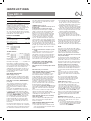
OJ Electronics EZC-12 Instruções de operação
- Tipo
- Instruções de operação

Type EZC-12
INSTRUCTIONS
English
EZC-12 microcenter is suitable for connecting
multiple room thermostats and electric
actuators (thermoheads) on, for example, an
underfloor heating system. The actuators must
be suitable for 230V AC, and the room
thermostats must either be suitable for 230V
AC, or be of the type having volt free terminals
only. Thermostats requiring a 24V live & neutral
must NOT be connected to EZC-12.
PRODUCT PROGRAMME
Product Type
Microcenter for 8 zones
incl. cover type ETT-KH EZC-12-8
Microcenter for 4 zones
incl. cover type ETT-KH EZC-12-4
CE marking
EMC: EN 61000-6-1:2001
EN 61000-6-3:2001
LVD: EN 60730-1
EN 60730-2-9
TECHNICAL DATA
Supply ............................ 230V AC +10% -15%
Input (EZC-12-8) ........................8 x 230V AC
(EZC-12-4) ........................4 x 230V AC
Output (EZC-12-8) .........8 x 230V AC, max. 2A
(EZC-12-4) .........4 x 230V AC, max. 2A
Demand relay ........2 x SPST, 230V AC max. 6A
Contact for time switch ...............................230V
Interrupter, main supply ..............only EZC-12-8
Fit the EZC to a suitable wall using the plugs
and screws provided. It will generally be found
more convenient if the unit is within 0.8 metre of
the manifold, as most electric actuators are
supplied with 1m leads. Cables can be run on
the surface into the terminal cover of the EZC,
or from within the wall to exit above or below
the EZC module.
ELECTRICAL INSTALLATION
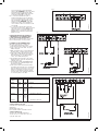
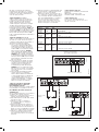
Mains supply (see fig. 1)
The EZC-12 requires a 230V AC mains supply
and this should be connected to the terminals
marked L, N, & PE under heading 230V supply.
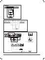
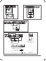
ELECTRIC ACTUATORS (THERMOHEADS)
(see fig. 4)
These actuators are fitted to the underfloor
heating manifolds and control the supply of
water through the various loops. For the
EZC-12 they must be suitable for 230V AC
power.
Connect the Live (BROWN) wire of the head
that will be controlled by room thermostat no. 1
to terminal 1 on the EZC under the heading
THERMOHEADS. Connect the neutral (BLUE)
wire to any of the N terminals on the EZC under
the heading THERMOHEADS. Then connect
the head that will be controlled by thermostat
No. 2 to terminal 2 and N in the same way.
N.B. It is permissible to connect more than 1
head to a single terminal, provided that both
heads are to be controlled by the same room
thermostats.
If not all room thermostats are to be used, but
more than 1 head is required to be controlled by
a single thermostat, it is permissible to link from
the switched live terminal of the thermostat to
any spare numbered input terminal on the EZC.
Then connect the second head to the output
side of that terminal.
THERMOSTATS (see fig. 3)
(Connect only to terminals on the top row of
the EZC unit)
A) Thermostats for 230 V power supply.
If using thermostats that require a 230V power
supply, connect the live power terminal of the
thermostat to any of the L terminals on the
EZC top row. Connect the thermostat neutral
terminal to any of the N terminals on the EZC
top row. Connect the switched live terminal
on the thermostat to terminal 1 on the EZC
top row. This thermostat will now operate the
electric actuator connected to terminal 1 on the
EZC under the heading THERMOHEADS on the
lower row. The second room thermostat should
be connected in the same way, but with the
switched live being connected to terminal 2 on
the EZC. Up to 8 thermostats can be connected
to EZC 12-8, and up to 4 thermostats to EZC
12-4.
B) Thermostats that do not require a power
supply
These thermostats should not have a neutral
terminal. Therefore, connect as above but
disregard the connection to the N terminals on
the EZC-12. A Clock thermostat can also be
used in place of a standard room thermostat. In
most case these devices are battery operated
and should be connected in this way.
APPLICATIONS USING TIME CONTROL
EZC with remote clock switching off the
installation during night times.
EZC with remote clock making night setback
(NSB).
EZC without any clock function.
Application EZC with remote clock switching
off the installation during nighttimes
Connecting a s.p.s.t. time switch across the
time channel terminals I & O in place of the
factory fitted link, gives a time control option
for all the thermostats connected to the EZC.
If the Time channel terminals are linked the
thermostats have power connected and will
regulate according to the thermostats setpoints.
If the time channel terminals are ”open” the
power to the thermostats is disconnected and
the thermostats are not in operation.
For this application DO NOT CONNECT the link
wire between terminals I and O on the lower left
hand side of the EZC under the heading NSB
LINK.
Do not connect a cable for the night setback
signal to the thermostats. If Night setback
signal is connected to the thermostats, they will
continually be in night setback mode.
Application EZC with remote clock making
night setback (NSB)
Connect a cable for the NSB signal from the
EZC to the thermostats if a night setback
function is required.
NIGHT SETBACK WIRING INSTRUCTIONS
Make the following connections:
1. Insert a link wire between terminals I and O
on the lower left hand side of the EZC under
the heading NSB LINK.
2. Ascertain whether the thermostats that you
are using have a night setback switching
facility, and if so, does the switching need to
be made to a NEUTRAL or LIVE connection.
3. If NEUTRAL, insert a link wire between
terminals C and N on the upper left hand side
of the EZC under the heading TYPE OF NSB.
4. If LIVE, insert a link wire between terminals C
and L on the upper left hand side of the EZC
under the heading TYPE OF NSB.
5. Four terminals are provided to bring
the setback switching wires from each
thermostat to the EZC. These are terminals
marked NSB, and can be used irrespective of
2 above.
When the connection between the time channel
I & O terminals is made by the time switch, the
thermostats will work to the day setpoint. If the
connection is opened by the time switch the
thermostats will work to the night setback point.
NOTE:
If you are not sure whether the night setback
switching of your thermostat goes to NEUTRAL
or LIVE, DO NOT connect the NSB link, see
item 3 and 4, until you have checked this
with the thermostat manufacturer. Incorrect
insertion of the link will cause a short circuit
and possible damage.
The OJ Electronics MTU 1999 (240V) has night
setback options. We recommend using this
thermostat, in which case you should connect
the link as per item 3 above. (Link wire between
terminals C and N on the upper left hand side)
Application without any clock functions
Connect a link wire across the time channel
terminals I & O. The EZC will maintain power to
the thermostats and if heating demands arise
open the thermohead and activate the demand
relays.
It is not necessary to connect the wire link
between terminals I and O on the lower left
hand side of the EZC under the heading NSB
LINK.
Do not connect the night setback signal
to the thermostats. If Night setback signal
is connected to the thermostats, they will
continually be in night setback mode.
PUMP OUTPUT (see fig. 5)
EZC-12 has a volt free relay output for pump
control that will be energised when any
connected room thermostat calls for heat. To
connect the pump, take a link from terminal L
under the heading 230V to terminal 0 under the
heading PUMP. Connect the pump L terminal
to terminal I under the heading PUMP on the
EZC-12. Connect the pump N terminal to the N
terminal of the EZC under the heading 230V.
Connect the pump PE terminal to PE on the
EZC.
DEMAND OUTPUT (see fig. 6)
EZC-12 has a second volt free relay output that
can be used to enable a boiler, or to open a
motorised valve.
A) To control a boiler that requires switching of
the live supply, take a link from EZC terminal
L under the 230V heading to EZC terminal I
under the heading DEMAND.
Type: EZC-12 1
57595B 10/18 (JRK)
© 2018 OJ Electronics A/S

Connect the boiler L to EZC terminal O
under heading DEMAND. Connect the boiler
N terminal to the N terminal on the EZC
under the heading 230V, and the boiler PE
to the EZC terminal PE. (see fig. 6A).
B) To control a boiler that has a pair of
terminals dedicated for remote switching
(e.g. by a room thermostat), connect these
remote terminals to EZC terminals O & I
under the heading DEMAND. As the EZC
terminals are volt free it is permissible to
connect either a 230V or a 24V boiler circuit.
(see fig. 6B).
C) To control a motorised valve, follow the
instructions in par. A above. Many motorised
valves have wires coloured BROWN and
BLUE for power connections. In this case
BROWN goes to the EZC terminal O and
BLUE goes to N.
PLEASE ENSURE THAT ALL WIRING IS
CARRIED OUT IN ACCORDANCE WITH
LOCAL ELECTRICAL REGULATIONS
When wiring is completed, fit the cover on the
EZC module using the screws provided.
POWERED UP RECOMMENDATIONS
When all connections are complete, we
recommend the following procedure:
1) Turn all thermostats to their lowest setting.
2) Turn on the power to the EZC. The green
LED should glow.
3) Make sure that the time control, if fitted, is in
the ON position, or that the link is in place.
4) Turn up the setting of the first thermostat
until it switches ON. Most thermostats have
either an indicator, or you will hear them
”click”. The red LED should glow.
5) Check that the thermoheads connected to
that thermostat is open. This may take up to
5 minutes from cold.
6) Check that the PUMP and BOILER/VALVE
are operating. The red LED will glow when
the relay is activated.
7) Turn up each thermostat in turn and make
sure that the thermoheads open, and that the
water circulation is going to the correct area.
N.B. If the heads appear to be in the wrong
position on the manifold, it may be simpler
to change them on the manifold, rather than
re-connecting them on the EZC.
Links connected
Time NSB Type
Control
Action link of NSB Function
On (Day) 1. Operating in day mode
Out None
Off (Night) 2. OFF
On (Day) 3. Operating in day mode
Neutral
In Connect
C to N
Off (Night) 4. Operating in NSB mode
On (Day) 5. Operating in day mode
Line
In connect
C to L
Off (Night) 6. Operating in NSB mode
Combinations with links for time control
OJ ELECTRONICS (UK) LTD.
Crusader House, Roman Way, Crusader Park
Warminster
Wiltshire BA12 8SP, U.K.
Phone 01985 213003 · Fax 01985 213310
OJ ELECTRONICS A/S
Stenager 13B · DK-6400 Sønderborg
Tel +45 73 12 13 14 · Fax +45 73 12 13 13
[email protected] · www.oj.dk
Fig. 2
2
© 2018 OJ Electronics A/S
Fig. 1
BR901A32ABR901A33A
Fig. 3
BR901A34A

3
© 2018 OJ Electronics A/S
Fig. 4
BR901A27A
Fig. 5
BR901A15
Fig. 6A
Fig. 6B
Fig. 6C
BR901A29A, BR901A31A, BR901A30A

4
The trademark is registered and belongs to OJ Electronics A/S · © 2018 OJ Electronics A/S
OJ ELECTRONICS A/S
Stenager 13B · DK-6400 Sønderborg
Tel. +45 7312 1314 · Fax +45 7312 1313
[email protected] · www.ojelectronics.com
EZC-12
HEAT DEMAND
PUMP DEM.
TIMENSB LINK
SUPPLY
230V
230V THERMO HEADS
TYPE OF NSB
POWER
MICROCENTER
230V ROOM THERMOSTATS
I
O
I
L
O
N
PE
1
N
I
O I
O
N
1
1 2
4
3
5
N
678
N
11
4
3
2
L
111
L
1
N
1
NSBNLC
N
11
NN
NSB
LL
1
8765
1
LINK LINK
L
N
PE
LINK
N L
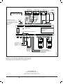
UNDERFLOOR
PUMP
MAINS SUPPLY
230VAC FROM
10 AMP FUSED
ISOLATOR
VOLT FREE OUTPUT FOR
BOILER CONTROL, OR
DEMAND SIGNAL FOR
COMPENSATOR
HEAD 1
HEAD 2 HEAD 7
HEAD 6
STAT 7
STAT 4
1 5
MTU-1999
MTD3-1999
2 421 4 5
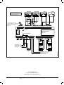
BASIS WIRING DIAGRAM FOR
230V MICROCENTER EZC 12-8
WITH NIGHT SETBACK
I
0
BR901A17D
LINK
LINK
For night setback insert one of
the two links depending on the type of
thermostat (see EZC instructions)
MTU: L-C
MTD3: C-N
Fig. 7
BR901A17D

© 2018 OJ Electronics A/S
Tipo EZC-12
INSTRUÇÕES
Português
Escrito segundo o novo acordo ortográfico.
A centralina EZC-12 permite a ligação de
diversos termóstatos e atuadores elétricos
(cabeças eletrotérmicas) em, por exemplo,
sistemas de aquecimento por piso radiante
hidráulico. Os atuadores devem ser adequados
para alimentação com 230 V AC, e os
termóstatos devem ser para alimentação com
230V AC ou do tipo (apenas) com terminais sem
tensão. Os termóstatos com fase e neutro de 24
V NÃO devem ser ligados ao módulo EZC-12.
LINHA DE PRODUTOS
Produto Tipo
Centralina para 8 zonas
incluindo tampa de tipo ETT-KH EZC-12-8
Centralina para 4 zonas
incluindo tampa de tipo ETT-KH EZC-12-4
Marca CE
Compatibilidade eletromagnética:
EN 61000-6-1:2001
EN 61000-6-3:2001
LVD
(DIRETIVA DE BAIXA TENSÃO): EN 60730-1
EN 60730-2-9
DADOS TÉCNICOS
Alimentação ................... 230 V AC +10%/-15%
Entrada (EZC-12-8) .......................8 x 230 V AC
(EZC-12-4) ......................................4 x 230 V AC
Saída (EZC-12-8) ........... 8 x 230 V AC, máx. 2A
(EZC-12-4) ..................... 4 x 230 V AC, máx. 2A
Relé de comando 2 x
monopolar, monoestado ..... 230 V AC, máx. 6 A
Contacto para o relógio.............................. 230V
Interruptor,
alimentação principal ............apenas EZC-12-8
Instalar o EZC numa parede adequada com as
buchas e os parafusos fornecidos. Normalmente,
para uma maior conveniência, a unidade deve
estar situada a menos de 0,8 m do coletor, já
que a maior parte dos atuadores elétricos são
fornecidos com cabos de 1 m. Os cabos podem
ser encaminhados à superfície para a tampa do
EZC, ou desde o interior da parede até saírem
por cima ou abaixo do módulo EZC.
INSTALAÇÃO ELÉTRICA
Alimentação da rede (ver a fig. 1)
O módulo EZC-12 deve ser alimentado com
corrente de 230 V AC; a ligação deve ser
efetuada nos terminais L (fase), N (neutro) e PE
por baixo da indicação Supply 230V.
ATUADORES ELÉTRICOS
(CABEÇAS ELETROTÉRMICAS)
(ver a fig. 4)
Os atuadores são adequados para serem
instalados nos coletores do sistema de
aquecimento por piso radiante e controlam o
caudal de água quente nos diversos circuitos da
instalação. Para o módulo EZC-12, os atuadores
devem ser de 230 V AC.
Ligar o condutor de FASE (CASTANHO) do
atuador a ser controlado pelo termóstato n.º 1
ao terminal 1 no EZC por baixo da indicação
THERMOHEADS. Ligar o condutor de NEUTRO
(AZUL) a um dos terminais N do EZC situados
por baixo da indicação THERMOHEADS.
5
57595B 10/18 (JRK)
Depois, ligar o atuador a ser controlado pelo
termóstato n.º 2 ao terminal 2 e ao terminal de
NEUTRO (N) conforme indicado acima.
IMPORTANTE: É possível ligar mais de um
atuador elétrico a um só terminal, desde que
ambos os atuadores sejam controlados pelos
mesmos termóstatos.
Se não forem utilizados todos os termóstatos,
mas se for necessário que mais do que um
atuador seja controlado por um só termóstato,
é possível fazer a ligação do terminal de FASE
(comutado) a um dos terminais de reserva
numerados no módulo EZC. Depois, ligar o
segundo atuador ao lado da saída do mesmo
terminal.
TERMÓSTATOS (ver a fig. 3)
(Ligar apenas aos terminais na régua
superior do módulo EZC)
A) Termóstatos com alimentação de 230 V.
Se forem utilizados termóstatos de 230V, ligar
o terminal de FASE a um dos terminais L na
régua superior do módulo EZC. Ligar o terminal
de NEUTRO do termóstato a um dos terminais
N na régua superior do módulo EZC. Ligar o
terminal de FASE (comutado) do termóstato
ao terminal 1 da régua superior do módulo
EZC. Este termóstato permite a operação
do atuador elétrico ligado ao terminal 1 do
módulo EZC situado por baixo da indicação
THERMOHEADS na régua inferior. O segundo
termóstato deve ser ligado da mesma maneira,
mas com o terminal de FASE (comutado) ligado
ao terminal 2 do módulo EZC. Podem ser
ligados até 8 termóstatos ao módulo EZC 12-8
e até 4 termóstatos ao módulo EZC 12-4.
B) Termóstatos que não necessitam de
alimentação elétrica
Estes terminais não devem ter terminal de
NEUTRO. Assim, fazer a ligação destes
termóstatos conforme indicado anteriormente,
mas ignorando a ligação aos terminais N no
módulo EZC-12. Pode ainda ser utilizado
um termóstato programável em vez de um
termóstato normal. Normalmente, estes
dispositivos são alimentados a bateria e devem
ser ligados desta maneira.
APLICAÇÕES COM RELÓGIO
EZC com relógio remoto para desligar a
instalação durante a noite.
EZC com relógio remoto para redução
noturna da temperatura (NSB ou “Night
Setback”).
EZC sem qualquer função de relógio.
Aplicação EZC com relógio remoto para
desligar a instalação durante a noite
Ligar um relógio monopolar, mono-estado
nos terminais do canal de tempo (“time”) I e
O em vez da ligação de fábrica, para dispor
de uma opção de temporização para todos
os termóstatos ligados ao módulo EZC. Se os
terminais do canal de tempo forem ligados, os
termóstatos têm a alimentação ligada e efetuam
a regulação de acordo com as regulações
dos termóstatos. Se os terminais do canal
de tempo estiverem “abertos”, a alimentação
dos termóstatos é desligada e os termóstatos
deixam de estar em funcionamento.
Para esta aplicação, NÃO LIGAR o fio de
ligação entre os terminais I e O no lado
inferior esquerdo do módulo EZC por baixo da
indicação NSB LINK.
Não ligar nenhum cabo para o sinal da redução
noturna da temperatura aos termóstatos. Se
o sinal da redução noturna da temperatura
for ligado aos termóstatos, estes ficam
continuamente no modo de operação noturno.
Aplicação EZC com relógio remoto para
redução noturna da temperatura (NSB ou
“Night Setback”).
Ligar um cabo para o sinal de redução
noturna da temperatura do módulo EZC aos
termóstatos, se for necessária a função de
redução noturna da temperatura.
INSTRUÇÕES PARA LIGAÇÃO DA
FUNÇÃO DE REDUÇÃO NOTURNA DA
TEMPERATURA
Efetuar as ligações seguintes:
1. Introduzir um fio de ligação entre os terminais
I e O no lado inferior esquerdo do módulo
EZC por baixo da indicação NSB LINK.
2. Verificar se os termóstatos utilizados na
instalação dispõem da função para redução
noturna de temperatura, e, em caso
afirmativo, se a comutação deve ser efetuada
com uma ligação à FASE ou ao NEUTRO.
3. Se a ligação for ao NEUTRO, introduzir um
fio de ligação nos terminais C e N no lado
superior esquerdo do módulo EZC por cima
da indicação TYPE OF NSB.
4. Se a ligação for à FASE, introduzir um fio de
ligação nos terminais C e L no lado superior
esquerdo do módulo EZC por cima da
indicação TYPE OF NSB.
5. Existem 4 terminais para ligar os cabos
para redução noturna da temperatura desde
os termóstatos até ao módulo EZC. Estes
terminais estão identificados com NSB, e
podem ser utilizados independentemente
dos dois terminais referidos anteriormente.
Quando a ligação entre os terminais I e O
do canal de tempo é efetuada pelo relógio,
os termóstatos funcionam de acordo com a
temperatura diurna. Se a ligação for aberta pelo
relógio, os termóstatos funcionarão de acordo
com a temperatura noturna.
NOTA:
Se não houver a certeza de que a comutação
da redução noturna de temperatura é ligada
ao NEUTRO ou à FASE, NÃO ligar a ligação
NSB (ver os pontos 3 e 4), até ser obtida a
confirmação do fabricante do termóstato. A
ligação incorreta do termóstato provoca um
curto-circuito e a sua possível danificação.
Os termóstatos OJ Electronics MTU2 1999
(230 V) dispõem de funções para redução
noturna da temperatura. Recomendamos a
utilização deste termóstato; assim, a ligação
deve ser efetuada conforme indicado no ponto
3 anterior. (Fio de ligação entre os terminais C e
N, no lado superior esquerdo)
Aplicação sem funções de relógio
Ligar um fio nos terminais I e O do canal de
tempo. O EZC mantém a alimentação dos
termóstatos e, se for pedido aquecimento, abre
o atuador eléctrico e ativa os relés de comando.

Não ligar o sinal de redução noturna da
temperatura aos termóstatos. Se o sinal da
redução noturna da temperatura for ligado aos
termóstatos, estes ficam continuamente no
modo de operação noturno.
SAÍDA DA BOMBA (ver a fig. 5)
O EZC-12 dispõe de um relé de saída com
contacto livre de tensão para colocação da
bomba de circulação em funcionamento
quando qualquer termóstato do sistema
solicitar a ligação do aquecimento. Para ligar
a bomba, fazer uma ligação do terminal L
por baixo da indicação SUPPLY 230V para o
terminal 0 por baixo da indicação PUMP. Ligar
o terminal L da bomba ao terminal I por baixo
da indicação PUMP no módulo EZC-12. Ligar o
terminal N da bomba ao terminal N do módulo
EZC por baixo da indicação SUPPLY 230V.
Ligar o terminal PE da bomba ao terminal PE no
módulo EZC.
SAÍDA DE COMANDO (ver a fig. 6)
O EZC-12 está equipado com um segundo relé
de saída com contacto livre de tensão para
comando de uma bomba de calor/caldeira ou
abertura de uma válvula motorizada.
A) Para o controlo de uma caldeira que
necessite da comutação da alimentação
da FASE, fazer uma ligação do terminal
L do módulo EZC por baixo da indicação
SUPPLY 230V com o terminal I do módulo
EZC por baixo da indicação DEMAND.
Ligar o terminal L da caldeira ao terminal
O do módulo EZC por baixo da indicação
DEMAND. Ligar o terminal N da caldeira
ao terminal N do módulo EZC por baixo da
indicação SUPPLY 230V; e ligar o terminal
PE da caldeira ao terminal PE do módulo
EZC. (ver a fig. 6A)
B) Para controlo de um caldeira com um par
de terminais para comutação remota (por
exemplo por um termóstato), ligar estes
terminais remotos aos terminais O e I
do módulo EZC por baixo da indicação
DEMAND. Como os terminais do módulo
EZC são isentos de tensão, é possível ligar
um circuito de 230 V ou 24 V da caldeira.
(ver a fig. 6B)
C) Para controlar uma válvula motorizada,
seguir as instruções no parágrafo A
anterior. Muitas válvulas motorizadas têm
os cabos de alimentação com bainhas de
cor CASTANHO e AZUL. Neste caso, o
condutor CASTANHO deve ser ligado ao
terminal O do módulo EZC e o condutor
AZUL deve ser ligado ao terminal N.
TODAS AS LIGAÇÕES E CABLAGENS
DEVEM OBSERVAR OS CÓDIGOS E
REGULAMENTOS E VIGOR
Após a realização das ligações, instalar a tampa
no módulo EZC com os parafusos fornecidos.
RECOMENDAÇÕES PARA LIGAÇÃO DA
ALIMENTAÇÃO
Após a realização das ligações, recomendamos
a realização das seguintes operações:
1) Ligar todos os termóstatos para o ponto de
regulação (temperatura) mais baixo.
2) Ligar a alimentação do módulo EZC. O LED
verde deve acender.
3) Verificar se o relógio, se instalado, se
encontra ligado (ON) ou se a ligação se
encontra instalada.
4) Aumentar a temperatura de regulação no
primeiro termóstato, até este ligar. A maior
parte dos termóstatos tem um indicador de
ligação ou esta é acompanhada por um ruído
audível (clic). O LED vermelho deve acender.
5) Verificar se os atuadores elétricos ligados
a esse termóstato abrem. Este processo
pode demorar até 5 minutos, se a instalação
estiver fria.
Ligações ligadas
Ação da NSB Type
Verificação
da Hora link of NSB Funcionamento
On (Dia) 1. Operação em modo diurno
Ausência Nenhuma
Off (Noite) 2. OFF
On (Dia) 3. Operação em modo diurno
NEUTRO
Entrada Ligar
C a N
Off (Noite) 4. Operação em modo de RNT
On (Dia) 5. Operação em modo diurno
FASE
Entrada Ligar
Off (Noite) C a L
6. Operação em modo de RNT
6) Verificar se a bomba e a caldeira/válvula estão
em funcionamento. O LED vermelho acende
quando o relé se encontra ativado.
7) Aumentar a regulação dos termóstatos, um a
um, e verificar se os atuadores elétricos abrem
e que a circulação da água é efetuada para a
área correta. IMPORTANTE: Se os atuadores
parecerem estar em posição incorreta no
coletor, a opção mais simples deverá ser
mudar a sua posição no coletor, em vez de
mudar a sua “ligação” no módulo EZC.
Fig. 2
Fig. 1
6
© 2018 OJ Electronics A/S
OJ ELECTRONICS (UK) LTD.
Crusader House, Roman Way, Crusader Park
Warminster
Wiltshire BA12 8SP, Reino Unido
Tel: 01985 213003 · Fax: 01985 213310
OJ ELECTRONICS A/S
Stenager 13B · DK-6400 Sønderborg
Tel.: +45 73 12 13 14 · Fax: +45 73 12 13 13
[email protected] · www.oj.dk
Combinações com ligações para temporização
RNT = Redução Noturna de Temperatura (NSB em Inglês)
NSB link = Ligação da RNT
Type of NSB = Tipo de RNT
ALIMENTAÇÃO COM
FUSÍVEL-SECCIONADOR DE 230 V
BR901A32A
CONTACTOS LIVRES
DE TENSÃO
RELÓGIO COM CONTACTOS
LIVRES DE TENSÃO
RELÓGIO SEM CONTACTOS
LIVRES DE TENSÃO
BR901A33A

Fig. 4
TERMÓSTATO DE 230 V
COM TERMINAL DE NEUTRO
TERMÓSTATO COM CONTACTOS
LIVRES DE TENSÃO
Fig. 3
PUMP
VÁLVULA MOTORIZADA
Fig. 6A
ARRANQUE REMOTO
DOS TERMINAIS
DA BOMBA DE
CALOR/CALDEIRA
PUMP
TERMINAL DE FASE
DA CALDEIRA
Fig. 6B
Fig. 6C
7
© 2018 OJ Electronics A/S
BR901A34A
CABEÇAS ELETROT
É
RMICAS
ATUADORES ELÉTRICOS DE 230 V
BR901A27A
230 V
PUMP
THERMOHEADS
BOMBA DE
CIRCULAÇÃO
NSB LINK
TIME
SUPPLY
DEMAND
I
I
I
I
O
O O
O
N
N
L
PE
PE
BR901A15
E
N
L
Fig. 5
BR901A15
BR901A29A, BR901A31A, BR901A30A

8
A marca comercial OJ é uma marca registada da OJ Electronics A/S · © 2018 OJ Electronics A/S
OJ ELECTRONICS A/S
Stenager 13B · DK-6400 Sønderborg
Tel. +45 7312 1314 · Fax +45 7312 1313
[email protected] · www.ojelectronics.com
Nota:
Esta figura encontra-se traduzida na totalidade para uma melhor compreensão.
No entanto, deverá olhar para a versão inglesa (pag. 4 deste manual) quando
estiver a instalar o produto, nomeadamente no que se refere às palavras que
se encontram escritas na centralina e que estão em lingua inglesa.
EZC 12
PEDIDO DE AQUECIMENTO
PEDIDO DE BOMBA
TEMPO
LIGAÇÃO RNT
ALIMENTAÇÃO
230V
TIPO DE RNT
ALIMENTAÇÃO
CENTRALINA
TERMÓSTATOS 230 V
I
O
I
L
O
N
PE
1
N
I
O I
O
N
1
1
2
4
3
5
N
678
N
11
NLC
LIGAÇÃO
LIGAÇÃO
L
N
PE
LIGAÇÃO
N L
BOMBA PARA O
SISTEMA DE
AQUECIMENTO
POR PISO
RADIANTE
ALIMENTAÇÃO
230 V AC (COM
FUSÍVEL-
SECCIONADORL
DE 10 A)
SAÍDA LIVRE DE TENSÃO PARA
COMANDO DA BOMBA DE
CALOR/CALDEIRA OU SINAL DE
COMANDO PARA
COMPENSADOR
ATUADOR 1
ATUADOR 2 ATUADOR 7
ATUADOR 8
DIAGRAMA DE CABLAGEM
BÁSICO PARA A CENTRALINA
EZC 12-8 230 V COM REDUÇÃO
NOTURNA DE TEMPERATURA
(RNT)
I
0
BR901A17B
LIGAÇÃO
LIGAÇÃO
Para redução noturna da
temperatura (RNT), introduzir uma
das duas ligações, dependendo do
tipo de termóstato (ver as instruções
do módulo EZC)
MTU: L-C
MTD3: C-N
4
3
2
L
111
L
1
N
1
NSB
N
11
NN
NSB
LL
1
8765
1
STAT 7
STAT 4
1 5
MTU-1999
MTD3-1999
2 421 4 5
Fig. 7
BR901A17D
-
 1
1
-
 2
2
-
 3
3
-
 4
4
-
 5
5
-
 6
6
-
 7
7
-
 8
8


OJ Electronics EZC-12 Instruções de operação
- Tipo
- Instruções de operação
em outros idiomas
Artigos relacionados
Outros documentos
-
Grundfos PM 1 Installation And Operating Instructions Manual
-
 EZetil EZC25 User Instructions
-
Tefal BL1151AD Manual do usuário
-
Kenwood FP734 Manual do proprietário
-
Bticino 3486 Manual do usuário
-
Uponor Smatrix Wave Guia rápido
-
 Oregon Scientific RGR126N Manual do usuário
-
Siemens KD32VV70 Manual do usuário
-

