
© Copyright 2019, 3M
FORM NO: 5903233
REV: B
USER INSTRUCTION MANUAL
5903233 Rev. B
The Ultimate in Fall Protection
Boxed-Frame Rail
Fall Arrest System
1
8530345, 8530361
A
B
C
8530427
A
B
C
8530288
A
B
C
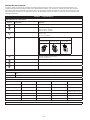
OSHA 1926.502
OSHA 1910.140

2
2
A
B
H
C
B
D
E
G
F

3
3
H
V
F
A
A≤30°
H ≤ 6’ (1.82 m)
H ≤ 6’ (1.82 m)
H ≤ 6’ (1.82 m)
H ≤ 6’ (1.82 m)
H ≤ 6’ (1.82 m)
H ≤ 6’ (1.82 m)
F
ft (m)
ß H - ft (m) à
0
(0.0)
1
(0.3)
2
(0.6)
3
(0.9)
4
(1.2)
5
(1.5)
6
(1.8)
ß V - ft (m) à
0
(0.0)
0.0
(0.0)
1.0
(0.3)
2.0
(0.6)
3.0
(0.9)
4.0
(1.2)
5.0
(1.5)
6.0
(1.8)
1
(0.3)
1.0
(0.3)
1.4
(0.4)
2.2
(0.7)
3.2
(1.0)
4.1
(1.3)
5.1
(1.6)
6.1
(1.9)
2
(0.6)
2.0
(0.6)
2.2
(0.7)
2.8
(0.9)
3.6
(1.1)
4.5
(1.4)
5.4
(1.6)
6.3
(1.9)
3
(0.9)
3.0
(0.9)
3.2
(1.0)
3.6
(1.1)
4.2
(1.3)
5.0
(1.5)
5.8
(1.8)
6.7
(2.0)
4
(1.2)
4.0
(1.2)
4.1
(1.3)
4.5
(1.4)
5.0
(1.5)
5.7
(1.7)
6.4
(2.0)
7.2
(2.2)
5
(1.5)
5.0
(1.5)
5.1
(1.6)
5.4
(1.6)
5.8
(1.8)
6.4
(2.0)
7.1
(2.2)
7.8
(2.4)
6
(1.8)
6.0
(1.8)
6.1
(1.9)
6.3
(1.9)
6.7
(2.0)
7.2
(2.2)
7.8
(2.4)
8.5
(2.6)
7
(2.1)
7.0
(2.1)
7.1
(2.2)
7.3
(2.2)
7.6
(2.3)
8.1
(2.5)
8.6
(2.6)
9.2
(2.8)
8
(2.4)
8.0
(2.4)
8.1
(2.5)
8.2
(2.5)
8.5
(2.6)
8.9
(2.7)
9.4
(2.9)
10.0
(3.0)
9
(2.7)
9.0
(2.7)
9.1
(2.8)
9.2
(2.8)
9.5
(2.9)
9.8
(3.0)
10.3
(3.1)
10.8
(3.3)
10
(3.0)
10.0
(3.0)
10.0
(3.1)
10.2
(3.1)
10.4
(3.2)
10.8
(3.3)
11.2
(3.4)
11.7
(3.6)
11
(3.4)
11.0
(3.4)
11.0
(3.4)
11.2
(3.4)
11.4
(3.5)
11.7
(3.6)
12.1
(3.7)
12.5
(3.8)
12
(3.7)
12.0
(3.7)
12.0
(3.7)
12.2
(3.7)
12.4
(3.8)
12.6
(3.9)
13.0
(4.0)
13.4
(4.1)
13
(4.0)
13.0
(4.0)
13.0
(4.0)
13.2
(4.0)
13.3
(4.1)
13.6
(4.1)
13.9
(4.2)
14.3
(4.4)
14
(4.3)
14.0
(4.3)
14.0
(4.3)
14.1
(4.3)
14.3
(4.4)
14.6
(4.4)
14.9
(4.5)
15.2
(4.6)
15
(4.6)
15.0
(4.6)
15.0
(4.6)
15.1
(4.6)
15.3
(4.7)
15.5
(4.7)
15.8
(4.8)
16.2
(4.9)
16
(4.9)
16.0
(4.9)
16.0
(4.9)
16.1
(4.9)
16.3
(5.0)
16.5
(5.0)
16.8
(5.1)
17.1
(5.2)
17
(5.2)
17.0
(5.2)
17.0
(5.2)
17.1
(5.2)
17.3
(5.3)
17.5
(5.3)
17.7
(5.4)
18.0
(5.5)
18
(5.5)
18.0
(5.5)
18.0
(5.5)
18.1
(5.5)
18.2
(5.6)
18.4
(5.6)
18.7
(5.7)
19.0
(5.8)
19
(5.8)
19.0
(5.8)
19.0
(5.8)
19.1
(5.8)
19.2
(5.9)
19.4
(5.9)
19.6
(6.0)
19.9
(6.1)
20
(6.1)
20.0
(6.1)
20.0
(6.1)
20.1
(6.1)
20.2
(6.2)
20.4
(6.2)
20.6
(6.3)
20.9
(6.4)
21
(6.4)
21.0
(6.4)
21.0
(6.4)
21.1
(6.4)
21.2
(6.5)
21.4
(6.5)
21.6
(6.6)
21.8
(6.7)
22
(6.7)
22.0
(6.7)
22.0
(6.7)
22.1
(6.7)
22.2
(6.8)
22.4
(6.8)
22.6
(6.9)
22.8
(7.0)
23
(7.0)
23.0
(7.0)
23.0
(7.0)
23.1
(7.0)
23.2
(7.1)
23.3
(7.1)
23.5
(7.2)
23.8
(7.2)
24
(7.3)
24.0
(7.3)
24.0
(7.3)
24.1
(7.3)
24.2
(7.4)
24.3
(7.4)
24.5
(7.5)
24.7
(7.5)
25
(7.6)
25.0
(7.6)
25.0
(7.6)
25.1
(7.6)
25.2
(7.7)
25.3
(7.7)
25.5
(7.8)
25.7
(7.8)
4
A
5 6
A. B. C. D.
E. F. G.
A B C

4
7
8
A
B
C
D
C
G1
G1
D
G1
X
C
G1
D
F
G
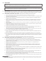
8A
XX.XX"
G1 G2 G3
8530345 36.00” 58.00” 48.00”
8530361 58.00” 112.50” 75.00”
8530427 113.00” 113.00” 95.00”
8530288 36.00” 48.00” 58.00”

5
8
A
H
G2
G3

6
8
A
B
36” [914 mm]
D
D
C
G1
G1
G1
G1
C
G
F
D
C
A
H
A
8B

7
8
G3
G2

8
9
1
2
3
5
4

9
10
1
A B C
11

10
11

FORM NO: 5908278 REV: A
11
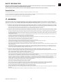
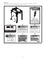
SAFETY INFORMATION
Please read, understand, and follow all safety information contained in these instructions prior to the use of this Flexiguard System.
FAILURE TO DO SO COULD RESULT IN SERIOUS INJURY OR DEATH.
These instructions must be provided to the user of this equipment. Retain these instructions for future reference.
Intended Use:
This Flexiguard System is intended for use as part of a complete fall protection or rescue system.
Use in any other application including, but not limited to, material handling, recreational or sports related activities, or other activities not described in
the User Instructions, is not approved by 3M and could result in serious injury or death.
This system is only to be used by trained users in workplace applications.
! WARNING
This Flexiguard System is part of a personal fall protection or rescue system. It is expected that all users be fully trained in the safe installation and
operation of the complete system. Misuse of this system could result in serious injury or death. For proper selection, operation, installation,
maintenance, and service, refer to all Product Instructions and all manufacturer recommendations, see your supervisor, or contact 3M Technical Service.
• To reduce the risks associated with transporting a Flexiguard system which, if not avoided, could result in serious injury or death:
- Ensure the system is properly secured or congured prior to transport. Refer to the User Instructions for detailed transportation requirements.
- Only transport below 5 mph (8 km/h) and at inclines of 10° or less, or as outlined in the User Instructions.
- Ensure the system will not contact overhead objects or electrical hazards while transporting or in use.
• To reduce the risks associated with working with a Flexiguard system which, if not avoided, could result in serious injury or death:
- Inspect all components of the system before each use, at least annually, and after any fall event, in accordance with the User Instructions.
- If inspection reveals an unsafe or defective condition, remove the system from service and repair or replace according to the User Instructions.
- Any system that has been subject to fall arrest or impact force must be immediately removed from service. Refer to the User Instructions or
contact 3M Fall Protection.
- The substrate or structure on which the system is attached/positioned must be able to sustain the static loads specied for the system in the
orientations permitted in the User Instructions or Installation Instructions.
- Do not exceed the number of allowable users as per the User Instructions.
- Never attach to a system until it is fully assembled, positioned, adjusted, and installed. Do not adjust the system while a user is attached.
- Never work outside the safe work area as dened by the User Instructions.
- Do not connect to the system while it is being transported or installed.
- Always maintain 100% tie-off when transferring between anchor points on the system.
- Use caution when installing, using, and moving the system as moving parts may create potential pinch points.
- Ensure proper lockout/tagout procedures have been followed when applicable.
- Only connect fall protection subsystems to the designated anchorage connection point on the system.
- When drilling holes for assembly or installation of the system, ensure no electric lines, gas lines, or other critical materials or equipment will be
contacted by the drill.
- Ensure that fall protection systems/subsystems assembled from components made by different manufacturers are compatible and meet the
requirements of applicable standards, including the ANSI Z359 or other applicable fall protection codes, standards, or requirements. Always
consult a Competent or Qualied Person before using these systems.
• To reduce the risks associated with working at heights which, if not avoided, could result in serious injury or death:
- Ensure your health and physical condition allow you to safely withstand all of the forces associated with working at height. Consult with your
doctor if you have any questions regarding your ability to use this equipment.
- Never exceed allowable capacity of your fall protection equipment.
- Never exceed maximum free fall distance of your fall protection equipment.
- Do not use any fall protection equipment that fails pre-use or other scheduled inspections, or if you have concerns about the use or suitability
of the equipment for your application. Contact 3M Technical Services with any questions.
- Some subsystem and component combinations may interfere with the operation of this equipment. Only use compatible connections. Consult
3M prior to using this equipment in combination with components or subsystems other than those described in the User Instructions.
- Use extra precautions when working around moving machinery (e.g. top drive of oil rigs) electrical hazards, extreme temperatures, chemical
hazards, explosive or toxic gases, sharp edges, or below overhead materials that could fall onto you or the fall protection equipment.
- Use Arc Flash or Hot Works devices when working in high heat environments.
- Avoid surfaces and objects that can damage the user or equipment.
- Ensure there is adequate fall clearance when working at height.
- Never modify or alter your fall protection equipment. Only 3M or parties authorized in by 3M may make repairs to the equipment.
- Prior to use of fall protection equipment, ensure a rescue plan is in place which allows for prompt rescue if a fall incident occurs.
- If a fall incident occurs, immediately seek medical attention for the fallen worker for the worker who has fallen.
- Do not use a body belt for fall arrest applications. Use only a Full Body Harness.
- Minimize swing falls by working as directly below the anchorage point as possible.
- If training with this device, a secondary fall protection system must be utilized in a manner that does not expose the trainee to an unintended
fall hazard.
- Always wear appropriate personal protective equipment when installing, using, or inspecting the device/system.
EN

12
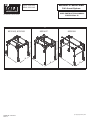
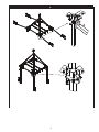
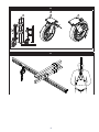
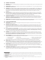
PRODUCT DESCRIPTION:
Figure 1 illustrates Flexiguard
®
Boxed-Frame Fall Arrest Systems (FAS). Typical components are illustrated in Figure 2 and
specied in Table 1. The Boxed-Frame FAS is a portable structure that supports an overhead anchorage. Boxed-Frame Rail
Systems are custom designed to customer requirements. Dimensions, number of rails, and number of legs will vary with the
intended application.
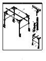
Table 1 – Specications
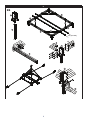
Component Specications:
Figure 2
Reference Component Materials
A
Box-Frame Aluminum and Steel
B
Trolley Rail Rail Halves - Aluminum
Stiffener Beam - Aluminum
Stiffener Bar - Aluminum
C
Trolley Wheels - Nylon
Bearings - Steel
Plate - Stainless Steel
D
Swiveling Wheel Assembly
Wheel Options:
8”
Solid Urethane
12”
Solid Rubber
16”
Pneumatic
E
Crank Jack Tube - Steel Tube
Mounting Plates - Steel Plate
Crank - Steel Bar
F
Leg Assembly Aluminum and Steel
G
Lifting Bar Steel Tube
H
Gusset Assembly Aluminum and Steel
System Specications:
Capacity: Maximum of 2 trolleys per trolley rail. 1 person per trolley, maximum of 310 lbs (141 kg) including clothes, tools, etc. per
Trolley.
Anchorage: Structure supporting the Fall Arrest System must be capable of withstanding a 8,000 lb (3,629 kg) vertical load.
System Dimensions:
Sizes 8530345 8530361 8530427 8530288
Overall Length (A) 19’ 1 1/8” [5820 mm] 23’ 4-1/8” [7115 mm] 23’ 7-1/2” [7201 mm] 23’ 3-3/8” [7096 mm]
Overall Width (B) 14’ 8” [4470 mm] 15’ 10” [4826 mm] 25’ [7623 mm] 12’ 10-11/16” [3929 mm]
Overall Height ( C ) 15’ [4572 mm] 22’ 3-1/2” [6795 mm] 31’ 10-3/8” [9712 mm] 13’ 3-3/4” [4058 mm] -
19’ 3-1/4” [5874 mm]
Rail Length 15’ 6” [4724 mm] 28’ [8534 mm] 32’ [9754 mm] 28’ [8534 mm]
Number of Rails 2 1 2 1
System Weight 1300 lbs. (590 kg) 1500 lb. (680 kg) 4370 lb. (916 kg) 1370 lb. (621 kg)
Gusset Dimensions: See Figure 7.

13
1.0 PRODUCT APPLICATION
1.1 PURPOSE: Flexiguard
™
Anchorage Systems are designed to provide anchorage connection points for a Personal Fall Arrest
System (PFAS).
1.2 SUPERVISION: Installation of this equipment must be supervised by a Qualied Person
1
. Use of this equipment must be
supervised by a Qualied Person
1
.
1.3 TRAINING: This equipment must be installed and used by persons trained in its correct application. This manual is to be
used as part of an employee training program as required by OSHA. It is the responsibility of the users and installers of
this equipment to ensure they are familiar with these instructions, trained in the correct care and use of this equipment,
and are aware of the operating characteristics, application limitations, and consequences of improper use of this
equipment.
1.4 RESCUE PLAN: When using this equipment and connecting subsystem(s), the employer must have a rescue plan and
the means at hand to implement and communicate that plan to users, authorized persons
2
, and rescuers
3
. A trained, on-
site rescue team is recommended. Team members should be provided with the equipment and techniques to perform a
successful rescue. Training should be provided on a periodic basis to ensure rescuer prociency.
1.5 INSPECTION FREQUENCY:
The Flexiguard
Anchorage System
shall be inspected by the user before each use and,
additionally, by a competent person other than the user at intervals of no longer than one year.
4
Inspection procedures are
described in the “Inspection and Maintenance Log”. Results of each Competent Person inspection should be recorded on
copies of the “Inspection and Maintenance Log”.
1.6 AFTER A FALL: If the Flexiguard Anchorage System is subjected to the forces of arresting a fall, it must be removed from
the eld of service immediately and replaced or inspected by an Authorized 3M Representative.
2.0 SYSTEM CONSIDERATIONS
2.1 ANCHORAGE: Structure on which the Flexiguard Anchorage System is placed or mounted must meet the Anchorage
specications dened in Table 1.
2.2 PERSONAL FALL ARREST SYSTEM: Figure 1 illustrates the application of this Flexiguard Anchorage System. Personal
Fall Arrest Systems (PFAS) used with the system must meet applicable OSHA, ANSI, state, and federal requirements.
The PFAS shall incorporate a Full Body Harness and Self-Retracting Device (SRD) with a 900 lb (4 kN) Average Arresting
Force.
2.3 FALL PATH AND SRL LOCKING SPEED: A clear path is required to assure positive locking of an SRL. Situations which
do not allow for an unobstructed fall path should be avoided. Working in confined or cramped spaces may not allow the
body to reach sufficient speed to cause the SRL to lock if a fall occurs. Working on slowly shifting material, such as sand
or grain, may not allow enough speed buildup to cause the SRL to lock.
2.4 HAZARDS: Use of this equipment in areas with environmental hazards may require additional precautions to prevent
injury to the user or damage to the equipment. Hazards may include, but are not limited to: heat, chemicals, corrosive
environments, high voltage power lines, explosive or toxic gases, moving machinery, sharp edges, or overhead materials
that may fall and contact the user or Personal Fall Arrest System.
2.5 FALL CLEARANCE: There must be sufcient clearance below the user to arrest a fall before the user strikes the ground
or other obstruction. Fall Clearance is dependent on the following factors:
• Deceleration Distance • Worker Height • Elevation of Anchorage Connector
• Free Fall Distance • Movement of Harness Attachment Element • Connecting Subsystem Length
See the Personal Fall Arrest System manufacturer’s instructions for specics regarding Fall Clearance calculation.
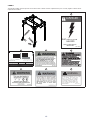
2.6 SWING FALLS: Swing Falls occur when the anchorage point is not directly above the point where a fall occurs (see).
The force of striking an object in a swing fall may cause serious injury or death. Minimize swing falls by working as
directly below the anchorage point as possible. Do not permit a swing fall if injury could occur. Swing falls will signicantly
increase the clearance required when a Self-Retracting Device or other variable length connecting subsystem is used.
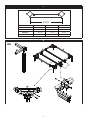
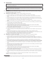
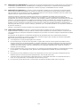
2.7 SHARP EDGES: Avoid working where Lifeline or Lanyard components of the Personal Fall Arrest System (PFAS) can
contact or abrade against unprotected sharp edges (see Figure 4). Where contact with a sharp edge is unavoidable, cover
the edge with protective material (A).
2.8 COMPONENT COMPATIBILITY: 3M equipment is designed for use with 3M approved components and subsystems
only. Substitutions or replacements made with non-approved components or subsystems may jeopardize compatibility of
equipment and may effect the safety and reliability of the complete system.
1 Qualied Person: A person with a recognized degree of professional certicate and with extensive knowledge, training, and experience in the fall protection
and rescue eld who is capable of designing, analyzing, evaluating, and specifying fall protections and rescue systems to the extent required by OSHA and other ap-
plicable standards.
2 Authorized Person: For purposes of the Z359 standards, a person assigned by the employer to perform duties at a location where the person will be exposed
to a fall hazard.
3 Rescuer: Person or persons other than the rescue subject acting to perform an assisted rescue by operation of a rescue system.
4 Inspection Frequency: Extreme working conditions (harsh environments, prolonged use, etc.)may require increasing the frequency of competent person
inspections.

14
2.9 CONNECTOR COMPATIBILITY: Connectors are considered to be compatible with connecting elements when they
have been designed to work together in such a way that their sizes and shapes do not cause their gate mechanisms to
inadvertently open regardless of how they become oriented. Contact 3M if you have any questions about compatibility.
Connectors (hooks, carabiners, and D-rings) must be capable of supporting at least 5,000 lbs. (22.2 kN). Connectors
must be compatible with the anchorage or other system components. Do not use equipment that is not compatible.
Non-compatible connectors may unintentionally disengage (see Figure 5). Connectors must be compatible in size, shape,
and strength. If the connecting element to which a snap hook or carabiner attaches is undersized or irregular in shape, a
situation could occur where the connecting element applies a force to the gate of the snap hook or carabiner (A). This force
may cause the gate to open (B), allowing the snap hook or carabiner to disengage from the connecting point (C).
Self-locking snap hooks and carabiners are required by ANSI Z359 and OSHA.
2.10 MAKING CONNECTIONS: Snap hooks and carabiners used with this equipment must be self-locking. Ensure all
connections are compatible in size, shape and strength. Do not use equipment that is not compatible. Ensure all
connectors are fully closed and locked.
3M connectors (snap hooks and carabiners) are designed to be used only as specied in each product’s user’s instructions.
See Figure 6 for examples of inappropriate connections. Do not connect snap hooks and carabiners:
A. To a D-ring to which another connector is attached.
A. In a manner that would result in a load on the gate. Large throat snap hooks should not be connected to standard
size D-rings or similar objects which will result in a load on the gate if the hook or D-ring twists or rotates, unless the
snap hook complies is equipped with a 3,600 lb (16 kN) gate. Check the marking on your snap hook to verify that it
is appropriate for your application.
B. In a false engagement, where features that protrude from the snap hook or carabiner catch on the anchor, and
without visual conrmation seems to be fully engaged to the anchor point.
C. To each other.
D. Directly to webbing or rope lanyard or tie-back (unless the manufacturer’s instructions for both the lanyard and
connector specically allows such a connection).
E. To any object which is shaped or dimensioned such that the snap hook or carabiner will not close and lock, or that
roll-out could occur.
F. In a manner that does not allow the connector to align properly while under load.

15
3.0 INSTALLATION
IMPORTANT: The Flexiguard
®
Boxed-Frame Rail Fall Arrest System must be assembled by a Qualied Person and the installation
must be certied by a Qualied Person as: meeting the criteria for a Certied Anchorage, or capable of supporting the potential forces
that could be encountered during a fall.
1
IMPORTANT: Do not alter or intentionally misuse this equipment. Consult 3M when installing or using this equipment in
combination with components or subsystems other than those described in this manual. Some subsystems and component combinations
may interfere with the operation of this equipment.
3.1 PLANNING: Plan your fall protection system prior to installation of the Flexiguard Boxed-Frame Fall Arrest System (FAS).
Account for all factors that may affect your safety before, during, and after a fall. Consider all requirements, limitations,
and specications dened in Section 2 and Table 1.
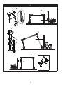
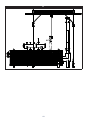
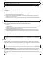
3.2 ASSEMBLING THE BOX FRAME: Figure 8A illustrates installation of the Box Frame:
1. Insert the setup bar (B) into the bottom of the corner assembly (A) in each corner of system.
2. Fasten cross bars (C&D) to all corner assemblies (A) using 1/2 inch hardware. Torque hardware to 60 ft*lbs (81
N*m).
3. Fasten top gussets (G1) to the cross bars (C&D) using 1/2 inch hardware. Torque hardware to 60 ft*lbs (81 N*m).
4. Fasten the rail bracket (F) to cross bar (C) using 1/2 inch hardware. Space the rail brackets (F) 36” [914 mm] a part
for dual rail systems and center single rails. Torque hardware to 60 ft*lbs (81 N*m).
5. Fasten the rail assembly (G) to the rail bracket (F) using the 1/2 inch hardware. Torque hardware to 60 ft*lbs (81
N*m).
6. Place the two ears from the leg assembly (H) between the two ears on the corner assembly (A) and fasten using the
5/8 inch hardware. Verify the bolt is able to rotate.
7. Attach lifting straps to the (4x) corners of the frame assembly.
8. Using an overhead crane, pick from all four corners of the frame and raise slowly into place. Place padding
underneath each leg assembly to allow the legs to slide along the ground.
9. Once the system is fully raised and the legs are vertical and slightly off the ground, lower the system onto the legs
but keep system supported by overhead crane.
10. Use personnel lift to fasten the leg assembly (H) to the corner assembly (A).
11. Install the remaining corner and side gussets (G2 and G3) and fasten using 1/2 inch hardware. Torque to 60 ft*lbs
(81 N*m).
12. Fasten the wheel assemblies to the upright using the 3/8 inch hardware. Torque to 45 ft*lbs (61 N*m).
13. If the system is adjustable in height, fasten the lifting brackets on each leg assembly above each adjustment pin and
fasten using 3/8 inch hardware. Torque hardware to 45 ft*lbs (61 N*m). See Figure 9.
14. Install the cross tube between each lifting bracket using the two pins provided.
3.3 ASSEMBLING THE 8530427 BOX FRAME: Figure 8B illustrates installation of the 8530427 Box Frame:
1. Insert the setup bar (B) into the bottom of the corner assembly (A) in each corner of system.
2. Fasten cross bar (C) to the plate of the corner assembly (A) using the 3/4 inch hardware. Fasten cross section (D)
between the two plates of the corner assembly (A) using the 3/4 inch hardware. Torque hardware to 130 ft*lbs (176
N-m).
3. Fasten top gussets (G1) to the cross bars (C) using 1/2 inch hardware. Torque hardware to 60 ft*lbs (81 N*m).
4. Fasten the (4x) rail bracket (F) around the bottom tube of cross bar (C) using 1/2 inch hardware. Space the brackets
36” [914 mm] a part on both sides of system centered on the cross bars (C). Torque hardware to 60 ft*lbs (81 N*m).
5. Fasten the rail assembly (G) to the rail bracket (F) using the 1/2 inch hardware. Torque hardware to 60 ft*lbs (81
N*m).
6. Place the two ears from the leg assembly (H) between the two ears on the corner assembly (A) and fasten using the
5/8 inch hardware. Verify the bolt is able to rotate.
7. Attach lifting straps to each corner of the system.
8. Using an overhead crane, pick from all four corners of the frame and raise slowly into place. Place padding
underneath each leg assembly to allow the legs to slide along the ground.
9. Once the system is fully raised and the legs are vertical and slightly off the ground, lower the system onto the legs
but keep system supported by overhead crane.
10. Use personnel lift to fasten the leg assembly (H) to the corner assembly (A) using the 3/4 inch hardware provided.
11. Install the remaining corner and side gussets (G2 & G3) and fasten using 1/2 inch hardware. Torque to 60 ft*lbs (81
N-m).
12. Fasten the wheel assemblies to the upright using the 3/8 inch hardware. Torque to 45 ft*lbs (61 N*m).
Towing: See instruction 5908365 for the Tow Bar Kit.
1 Qualied Person: A person with a recognized degree of professional certicate and with extensive knowledge, training, and experience in the fall protection
and rescue eld who is capable of designing, analyzing, evaluating, and specifying fall protections and rescue systems to the extent required by OSHA and other
applicable standards

16
WARNING: The Boxed-Frame Rail Fall Arrest System should be towed in a fully lowered position to limit the possibility of tip-overs
that may damage equipment or result in injury or death.
WARNING: Do not tow at speeds exceeding 5 mph (8 kph). Never tow the system on slopes greater than 10°. Excessive speed
or slope may cause system and tow vehicle tip-overs resulting in equipment damage, serious injury, or death.
3.4 LOWERING AND RAISING THE ADJUSTABLE BOXED-FRAME: On Boxed-Frame Rail FAS equipped with Adjustable
Legs and Lifting Bars, frame height can be adjusted with a Forklift or similar equipment (see Figure 9). To raise or lower
the Boxed-Frame:
1. Attach the Lifting Bar across two legs of the Box Frame with the provided fasteners.
2. Support the Lifting Bar with a forklift rated for lifting the weight of the Box Frame.
3. Raise or lower the Frame with the Wheel Assembly Crank Jacks until the pins can be removed from the adjustable
legs and then pull the pins out of the outer and inner leg tubes.
4. Raise the end of the Box Frame with the forklift. When the Box Frame is at the desired height, reinsert the pins
through the outer and inner leg tubes.
5. Repeat Steps 1 through 4 to raise the other end of the Box Frame. Insert the pins through corresponding pin holes on
the leg tubes so the same number of pin holes are exposed on each leg.
NOTE: Boxed-Frame models without a Lifting Bar may be lifted from the top cross structure or Lifting Eyes on the top of each leg if so
equipped.
3.5 POSITIONING AND STABILIZING THE BOXED-FRAME RAIL FALL ARREST SySTEM:
Position and stabilize the Boxed-Frame Rail FAS in the work area as illustrated in Figure 10:
1. For each leg:
A. Crank the Wheel Assembly Jack clockwise until the Caster Wheel contacts the ground and raises the Leg Stabilizer
Pad off the ground.
B. If present, pull the Swivel Lock Pin and rotate the Swivel Lock 90° to allow 360° rotation of the wheel.
C. If present, unlock the Wheel Lock so the wheel can roll.
2. Position the Boxed-Frame Rail Fall Arrest System as desired and then stabilize by adjusting each leg as follows:
A. Position the Boxed-Frame Rail(s) over the desired work area. When moving the system near overhead power
lines, electrical outlets, or any other dangerous overhead objects, always have a spotter present to prevent
accidental contact.
B. Crank the Wheel Assembly Jack counterclockwise until the Leg Stabilizer Pad contacts the ground firmly.
C. If present, pull the Swivel Lock Pin and rotate the Swivel Lock 90° to prevent the wheel from swiveling.
D. If present, lock the Wheel Lock to prevent the wheel from rolling.
WARNING: The Boxed-Frame Rail Fall Arrest System must be used on level ground. After positioning and stabilizing the Boxed-
Frame, inspect the system with a Level to ensure the entire system is within 1° of level. Using the system when not level could tip the
system, resulting in serious injury or death.
4.0 USE
4.1 BEFORE EACH USE: Ensure all 4 positioning wheels are raised before using the system as a fall arrest anchor point.
Verify that your work area and Personal Fall Arrest System (PFAS) meet all criteria dened in Section 2 and a formal
Rescue Plan is in place. Inspect the Boxed-Frame Rail FAS per the ‘User’ inspection points dened on the “Inspection and
Maintenance Log” (Table 2). If inspection reveals an unsafe or defective condition, do not use the Boxed-Frame Rail FAS.
Remove the system from service and contact 3M regarding replacement or repair.
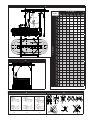
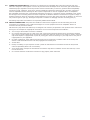
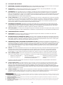
SAFE WORK AREA: Figure 3 illustrates the Safe Work Area for the Fall Arrest System. The gray shading on the table designates
safe working distances where the angle of the Lifeline is less than or equal to 30° from vertical and the Horizontal Distance (H) from the
anchorage connection point is less than or equal to 6 ft (1.82 m). NEVER work at a Horizontal Distance (H) and Vertical Distance (V) that
results in a calculated Vertical Fall Distance (F) exceeding the gray shaded values on the table in Figure 3.
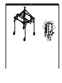
4.2 FALL ARREST CONNECTIONS: Figure 11 illustrates application of the Boxed-Frame Rail Fall Arrest System and its Fall
Arrest Connections. The Boxed-Frame Rail must always be used with a Full Body Harness and Fall Arrest subsystem.
Trolley Rails are equipped with Four-Wheel Trolleys that travels back-and-forth inside the Rail Halves. A Self-Retracting
Lifeline (SRL) can be connected to the eye on the Trolley. Connect the other end of the SRL to the back Dorsal D-Ring on
the Harness. A Tag Line can be attached to the SRL Lifeline and used to retrieve the lifeline for connection to the user’s
harness.
IMPORTANT: No more than one person, meeting the Capacity requirements specied in Table 1, shall be attached to each Trolley.

17
WARNING: Inappropriate or incompatible connections between components of the Personal Fall Arrest System (PFAS) may result in
serious injury or death. See Section 2 for details regarding connector compatibility and safe connections.

18
5.0 INSPECTION
5.1 INSPECTION FREQUENCY: The Anchorage System must be inspected prior to use. Inspection frequency, Inspection
ndings, date and corrective should be recorded in the “Inspection and Maintenance Log”. Inspect all other components of
the Fall Protection System per the frequencies and procedures as dened in the respective manufacturer’s instructions.
RFID: Some Anchorage Systems are equipped with an Radio Frequency Identication (RFID) Tag. The RFID Tag can be used in
conjunction with a Handheld Reading Device to simplify inspection and inventory control and provide records for you fall protection
equipment. If you are a rst-time user, contact 3M Fall Protection.
5.2 DEFECTS: If inspection reveals an unsafe or defective condition, remove the Anchorage System from service immediately
and contact 3M Fall Proection regarding replacement or repair. Do not attempt to repair the Anchorage System.
5.3 PRODUCT LIFE: The functional life of the Anchorage System is determined by work conditions and maintenance. As long
as the product passes inspection criteria, it may remain in service.
6.0 MAINTENANCE, SERVICING, STORAGE
6.1 CLEANING: Periodically clean the Anchorage System’s metal components with a soft brush, warm water, and a mild soap
solution. Ensure parts are thoroughly rinsed with clean water.
6.2 SERVICE: Only 3M Fall Protection or parties authorized in writing by 3M Fall Protection may make repairs to this
equipment. If the Anchorage System has been subject to fall force or inspection reveals an unsafe or defective
conditions, remove the system from service and contact 3M Fall Protection regarding replacement or repair.
6.3 STORAGE AND TRANSPORT: When not in use, or where appropriate, store and transport the Anchorage System and
associated fall protection equipment in a cool, dry, clean environment out of direct sunlight. Avoid areas where chemical
vapors may exist. Thoroughly inspect components after extended storage.

19
LABELS
The following labels must be present on the Box Frame. Labels must be replaced if they are not fully legible. Contact 3M for
replacement of labels.
C
D
E
F
G
A
F
G
A
C
D
E
B
A
Pt#: 16399
ELECTROCUTION
HAZARD
WATCH FOR OVERHEAD
POWER LINES
DANGER
B
SERIAL NO.:
Numéro de série:
Fabriqué(a/ m) Numéro de lot: Numéro du modèle: Longueur(m):
XXXXXX
3M.com/FallProtection
Red Wing, MN 55066, USA
C D
E F G
DO NOT REMOVE THIS LABEL . F U LLY
RETRACT O R ROTAT E JACK BEFORE
TOWING. ENGAGE LOCKING PIN ON SWIVEL
JACK BEFORE TOWING OR USING JACK.
BLOCKS USED TO INCREASE HEIGHT CAN
CAUSE INSTABILITY AND MAY CAUSE
INJURY OR DEATH.
WARNING
Pt# 18723 Rev.01
MAXIMUM LIFT CAPACITY 5000 Lbs/22kN

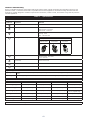
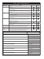
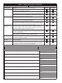
Table 2 – Inspection and Maintenance Log
Inspection Date: Inspected By:
Components: Inspection: (See Section 1 for Inspection Frequency) User
Competent
Person
Boxed-Frame Inspect the Boxed-Frame for structural defects or damage including bends,
corrosion, etc.
Inspect fasteners rail supports, wheel clamps, tow bar clamps, etc. to
ensure they are tight.
Visually inspect the gussets and support tubes for straightness. Ensure
there is no visible deformation or bend, indicating previous exposure to fall
arrest forces.
Trolley Rails Visually inspect fasteners on the trolley rails to ensure they are tight.
Inspect the rail tracks for structural defects. Rail tracks must be straight
without any bends or dents.
Visually inspect the trolleys for damage to the trolley and excessive wheel
wear. Ensure the trolleys roll freely in the trolley rails and the wheels are
securely attached.
Wheel Assemblies
and Crank Jacks
Inspect wheels and casters for excessive wear. Make sure wheels roll
smoothly and swivel on their casters. Inspect wheel locks and swivel locks
for proper operation. Make sure wheel and crank jack assemblies are
clamped securely to frame legs.
Inspect crank jacks for any wear, corrosion, or deformities. Make sure
crank jacks function properly.
If wheel assemblies and/or crank jacks have grease zerks, grease zerks
every 6 months.
Anchorage
Connection Points
Make sure all anchorage connection points are free of corrosion, cracks, or
other imperfections that my cause malfunction during operation.
Labels Verify that all labels are securely attached and are legible (see ‘Labels’).
PFAS and Other
Equipment
Additional Personal Fall Arrest System (PFAS) equipment (harness, SRL,
etc) that are used with the Flexiguard Anchorage System should be
installed and inspected per the manufacturer’s instructions.
Serial Number(s): Date Purchased:
Model Number: Date of First Use:
Corrective Action/Maintenance: Approved By:
Date:
Corrective Action/Maintenance: Approved By:
Date:
Corrective Action/Maintenance: Approved By:
Date:
Corrective Action/Maintenance: Approved By:
Date:
Corrective Action/Maintenance: Approved By:
Date:
Corrective Action/Maintenance: Approved By:
Date:
Corrective Action/Maintenance: Approved By:
Date:
Corrective Action/Maintenance: Approved By:
Date:
Corrective Action/Maintenance: Approved By:
Date:
A página está carregando...
A página está carregando...
A página está carregando...
A página está carregando...
A página está carregando...
A página está carregando...
A página está carregando...
A página está carregando...
A página está carregando...
A página está carregando...
A página está carregando...
A página está carregando...
-
 1
1
-
 2
2
-
 3
3
-
 4
4
-
 5
5
-
 6
6
-
 7
7
-
 8
8
-
 9
9
-
 10
10
-
 11
11
-
 12
12
-
 13
13
-
 14
14
-
 15
15
-
 16
16
-
 17
17
-
 18
18
-
 19
19
-
 20
20
-
 21
21
-
 22
22
-
 23
23
-
 24
24
-
 25
25
-
 26
26
-
 27
27
-
 28
28
-
 29
29
-
 30
30
-
 31
31
-
 32
32


3M DBI-SALA® FlexiGuard™ Box Frame System 8530345, 1 EA Manual do usuário
- Tipo
- Manual do usuário
- Este manual também é adequado para
em outras línguas
Artigos relacionados
-
3M 2104550 Instruções de operação
-
-
-
-
-
-
-
-
-
3M DBI-SALA® Shockwave™2 Shock Absorbing Lanyard 1244455, 1 ea Instruções de operação
Outros documentos
-
Husqvarna HUSO2022 Arborist Climbing Harness Manual do usuário
-
 BeamGrip FP Stryder™ Beam Anchor Manual do proprietário
-
Climbing Technology 7L928*HK Instruções de operação
-
Ingersoll-Rand Free Standing Workstation Cranes Informação do produto
-
Latchways Sealed Self-Retracting Lanyards Instruções de operação
-
Sharper Image RFID Combination Locking Wallet Manual do proprietário
