Ariston PK 630 RT GH Manual do proprietário
- Tipo
- Manual do proprietário

PK 741 RQO GH
PK 750 T GH
PK 630 RT GH
PK 640 RGH
PK 640.1 RX
Français
Mode d’emploi
TABLE DE CUISSON
Español
Manual de instrucciones
ENCIMERA
Portuges
Instruções para a utilização
PLANO
English
Operating Instructions
HOB
1
5
6
9
47
50
53
52
52
Contents
Operating Instructions,1
Warnings,3
Assistance,6
Description of the appliance,7
Installation,10
Start-up and use,15
Precautions and tips,16
Maintenance and care,17
Troubleshooting,17
Sommaire
Mode d’emploi,1
Avertissements,3
Assistance,6
Description de l’appareil,7
Installation,18
Mise en marche et utilisation,25
Précautions et conseils,26
Nettoyage et entretien,27
Anomalies et remèdes,27
Sumario
Manual de instrucciones,1
Advertencias,4
Asistencia,6
Descripción del aparato,8
Instalación,29
Puesta en funcionamiento y uso,34
Precauciones y consejos,35
Mantenimiento y cuidados,36
Anomalías y soluciones,36
Índice
Instruções para a utilização,1
Advertências,4
Assistência,6
Descrição do aparelho,8
Instalação,37
Início e utilização,42
Precauções e conselhos,43
Manutenção e cuidados,44
Anomalias e soluções,44

2
5
6
9
55
58
61
61
60

3
Warnings
WARNING: The appliance and its accessible parts
become hot during use. Care should be taken to
avoid touching heating elements. Children less than 8
years of age shall be kept away unless continuously
supervised. This appliance can be used by children
aged from 8 years and above and persons with
reduced physical, sensory or mental capabilities or
lack of experience and knowledge if they have been
given supervision or instruction concerning use of the
appliance in a safe way and understand the hazards
involved. Children shall not play with the appliance.
Cleaning and user maintenance shall not be made
by children without supervision.
WARNING: Unattended cooking on a hob with fat or
cooking surfaces.
WARNING: If the surface in glass-ceramic is cracked,
switch off the appliance to avoid the possibility of
electric shock.
Never use steam cleaners or pressure cleaners on
the appliance.
Remove any liquid from the lid before opening it. Do
not close the glass cover (if present) when the gas
burners or electric hotplates are still hot.
The appliance is not intended to be operated by
means of an external timer or separate remote
control system.
CAUTION: the use of inappropriate hob guards can
cause accidents.
Avertissements
accessibles deviennent très chauds pendant leur
fonctionnement. Il faut faire attention à ne pas toucher
les éléments chauffants. Ne pas faire approcher les
enfants de moins de 8 ans à moins qu’ils ne soient
sous surveillance constante. Le présent appareil peut
être utilisé par des enfants de plus de 8 ans et par
des personnes présentant des capacités physiques,
sensorielles ou mentales réduites ou n’ayant pas
l’expérience ou les connaissances indispensables,
à condition qu’ils soient sous bonne surveillance ou
qu’ils aient reçu les instructions nécessaires pour une
utilisation de l’appareil en toute sécurité et à condition
qu’ils se rendent compte des dangers encourus. Les
enfants ne doivent pas jouer avec l’appareil. Les
opérations de nettoyage et d’entretien ne doivent
pas être effectuées par des enfants non surveillés.
de l’huile ou de la graisse sur un foyer est dangereux
et risque d’entraîner un incendie. Il ne faut JAMAIS
essayer d’éteindre une flamme ou un incendie
avec de l’eau ! Il faut éteindre l’appareil et couvrir la
une couverture anti-feu.
d’objets sur les surfaces de cuisson.
d’électrocution.
Ne jamais nettoyer l’appareil avec des nettoyeurs
vapeur ou haute pression.
couvercle avant de l’ouvrir. Ne pas abaisser le
couvercle en verre (s’il y en a un) tant que les brûleurs
gaz ou la plaque électrique sont chauds.

4
Cet appareil ne peut pas être allumé au moyen
d’un temporisateur extérieur ou d’un système de
commande à distance séparé.
inappropriées peut causer des incendies.
Advertencias
vuelven muy calientes durante el uso. Por lo tanto, es
importante evitar tocar los elementos calentadores.
Mantenga alejados a los niños menores de 8 años si
puede ser utilizado por niños mayores de 8 años y
por personas con capacidades físicas, sensoriales
o mentales disminuidas o sin experiencia ni
conocimientos, si se encuentran bajo una adecuada
vigilancia o si han sido instruidos sobre el uso del
aparato de modo seguro y comprenden los peligros
relacionados con el mismo. Los niños no deben
jugar con el aparato. Las operaciones de limpieza y
de mantenimiento no deben ser realizadas por niños
sin vigilancia.
sin vigilancia puede ser peligroso y provocar un
incendio. NUNCA intente apagar una llama/incendio
con agua, se debe apagar el aparato y cubrir la llama,
por ejemplo, con una tapa o con una manta ignífuga.
agrietada, apague el aparato para evitar sacudidas
eléctricas.
No utilice nunca limpiadores a vapor o de alta presión
para la limpieza del aparato.
antes de abrirla. No cierre la tapa de vidrio (si existe)
cuando los quemadores o la placa eléctrica todavía
través de un temporizador externo o de un sistema
de mando a distancia.
de la placa de cocción puede provocar accidentes.
Advertências
acessíveis aquecem muito durante a utilização.
É preciso ter atenção e evitar tocar os elementos
que aquecem. Manter afastadas as crianças com
menos de 8 anos, caso não estejam a ser vigiadas.
O presente aparelho pode ser utilizado por crianças
com mais de 8 anos e por pessoas com capacidades
físicas, sensoriais ou mentais reduzidas ou com
pouca experiência e conhecimentos, caso sejam
adequadamente vigiadas ou caso tenham recebido
instruções em relação ao uso do aparelho de
forma segura e tenham conhecimento dos perigos
associados. As crianças não devem brincar com o
aparelho. As operações de limpeza e manutenção
não devem ser efectuadas por crianças sem
vigilância.
vigilância pode ser perigoso e provocar um incêndio.
com uma tampa ou com uma manta ignífuga.
sobre as superfícies de cozedura.
rachada, desligue o aparelho para evitar a
possibilidade de choques eléctricos.
Nunca utilize equipamento de limpeza a vapor ou
de alta pressão para limpar o aparelho.
abri-la. Não feche a tampa de vidro (se presente) se

5
os queimadores ou a chapa eléctrica ainda estiverem
quentes.
O aparelho não é destinado a ser colocado em
funcionamento por meio de um temporizador externo
ou por um sistema de comando à distância separado.
inadequadas pode causar incidentes.
8
8
8
8

6
Assistance
Communicating:
This information is found on the data plate located on the appliance and/or
on the packaging.
Assistance
Indiquez-lui :
appareil et/ou sur son emballage.
Asistencia
Comunique:
aparato y/o en el embalaje.
La siguiente información es válida solo para España.
Para otros países de habla hispana consulte a su vendedor.
Ampliación de garantía
Llame al 902.363.539
de garantía hasta 5 años.
Consiga una cobertura total adicional de
Y NO PAGUE AVERIAS NUNCA MAS
Servicio de asistencia técnica (SAT)
Llame al 902.133.133
funcionamiento.
la limpieza y mantenimiento de su electrodoméstico a precios competitivos.
ESTAMOS A SU SERVICIO
Assistência
Comunique:
no aparelho e/ou na embalagem.
.(.Mod
.(S/N
(Mod
(S/N

7
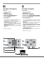
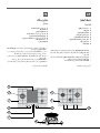
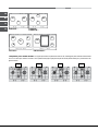
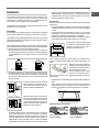
Description of the appliance
Overall view
1 Support Grid for COOKWARE
2 GAS BURNERS
3 CERAMIC GLASS MODULE*
4 Control Knobs for GAS BURNERS
5 INDICATOR LIGHT FOR CERAMIC GLASS MODULE*
6 Control Knobs for CERAMIC GLASS MODULE*
7 Ignition for GAS BURNERS*
8 SAFETY DEVICES*
INDICATOR LIGHT for CERAMIC GLASS MODULE switches on
whenever the selector knob is moved from the ‘off’ position.
GAS BURNERS differ in size and power. Use the diameter of the cookware
to choose the most appropriate burner to cook with.
GAS BURNERS and CERAMIC GLASS MODULE*
GAS BURNER IGNITION*
SAFETY DEVICE* stops the gas flow if the flame is accidentally
extinguished.
* Only available on certain models.
Description de l’appareil
Vue d’ensemble
1 Grilles support de CASSEROLES
2 BRÛLEURS À GAZ
3 TABLE DE CUISSON VITROCÉRAMIQUE*
4 Manettes de commande des BRÛLEURS GAZ
5 TABLE DE CUISSON VITROCÉRAMIQUE*
6 Manettes de commande des TABLE DE CUISSON VITROCÉRAMIQUE*
7 Bougie d’allumage des BRÛLEURS GAZ*
8 DISPOSITIF DE SÉCURITÉ*
FONCTIONNEMENT DES TABLE DE CUISSON
VITROCÉRAMIQUE* il s’allume dès que la manette n’est plus sur la
position éteint.
BRÛLEURS GAZ ils ont plusieurs dimensions et puissances. Choisissez
celui qui correspond le mieux au diamètre de votre casserole.
BRÛLEURS GAZ et de la TABLE DE
CUISSON VITROCÉRAMIQUE*
puissance.
BRÛLEURS GAZ* permet l’allumage
automatique du brûleur sélectionné.
DISPOSITIF DE SÉCURITÉ*
coupez immédiatement l’arrivée du gaz.
* N’existe que sur certains modèles.
1
1
4
4
2
2
4
8
7
3
6
5

8
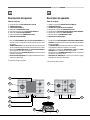
Descripción del aparato
Vista en conjunto
1 Parrillas de apoyo para RECIPIENTES DE COCCIÓN
2 QUEMADORES A GAS
3 PLACA VITROCERÁMICA*
4 Mandos de los QUEMADORES A GAS
5 Piloto de funcionamiento de la PLACA VITROCERÁMICA*
6 Mandos de las PLACA VITROCERÁMICA*
7 Bujía de encendido de los QUEMADORES A GAS*
8 DISPOSITIVO DE SEGURIDAD*
FUNCIONAMIENTO DE LA PLACA VITROCERÁMICA*: se
de apagado.
QUEMADORES A GAS:
QUEMADORES A GAS y de la PLACA VITROCERÁMICA*
para la regulación de la llama o de la potencia.
QUEMADORES A GAS:* permite el encendido
DISPOSITIVO DE SEGURIDAD:* si se apaga accidentalmente la llama,
interrumpe la salida de gas.
* Presente sólo en algunos modelos.
Descrição do aparelho
Vista de conjunto
1 Grades de suporte para RECIPIENTES DE COZEDURA
2 QUEIMADORES A GÁS
3 CHAPAS PARA COZER DE VIDRO CERÂMICA*
4 Selectores de comando dos QUEIMADORES A GÁS
5 Indicador luminoso DAS CHAPAS PARA COZER DE VIDRO CERÂMICA*
6 Selectores de comando das VIDRO CERÂMICA*
7 QUEIMADORES A GÁS*
8 DISPOSITIVO DE SEGURANÇA*
FUNCIONAMENTO CHAPA PARA COZER DE VIDRO
CERÂMICA* acende-se se o selector estiver em qualquer posição diferente
daquela de desligado.
QUEIMADORES
mais adequado ao diâmetro do recipiente a ser utilizado.
QUEIMADORES A GÁS e da VIDRO
CERÂMICA* para a regulação da chama ou da potência.
QUEIMADORES A GÁS* permite o acendimento
DISPOSITIVO DE SEGURANÇA* no caso em que a chama se apague
*
1
1
4
4
2
2
4
8
7
3
6
5

9
1
1
4
4
2
2
4
8
7
3
6
5
1
2
3
4
* 5
* 6
* 7
* 8
*
*
*
1
2
3
4
* 5
* 6
* 7
* 8
*
*
*

10
GB
Installation
! Before operating your new appliance please read this instruction booklet
carefully. It contains important information for safe use, installation and care
of the appliance.
! Please keep these operating instructions for future reference. Pass them on
to possible new owners of the appliance.
Positioning
! Keep packaging material out of the reach of children. It can become a choking
or suffocation hazard (see Precautions and tips).
!
instructions provided. Incorrect installation may cause harm to people and
animals or may damage property.
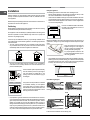
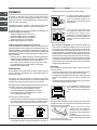
! This unit may be installed and used only in permanently ventilated rooms
in accordance with current national regulations. The following requirements
must be observed:
any combustion fumes. This may consist of a hood or an electric fan that
automatically starts each time the appliance is switched on.
In a chimney stack or branched flue.
(exclusively for cooking appliances)
Directly to
the Outside
3
/h
per kW of installed power.
The air circulation system may take air directly
from the outside by means of a pipe with an
inner cross section of at least 100 cm
2
; the
opening must not be vulnerable to any type
of blockages.
The system can also provide the air needed
for combustion indirectly, i.e. from adjacent
rooms fitted with air circulation tubes as
described above. However, these rooms must
not be communal rooms, bedrooms or rooms
rooms containing LPG cylinders must also be equipped with vents to allow
gas to escape in the event of a leak. As a result LPG cylinders, whether
partially or completely full, must not be installed or stored in rooms or
storage areas that are below ground level (cellars, etc.). It is advisable to
keep only the cylinder being used in the room, positioned so that it is not
etc. ) which could raise the temperature of the cylinder above 50°C.
A
Examples of
ventilation holes
for comburant air.
Enlarging the ventilation slot
between window and floor.
Adjacent
Room
Room to be
Vented
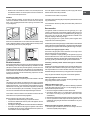
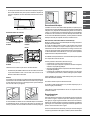
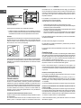
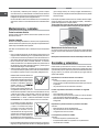
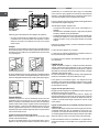
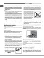
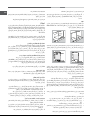
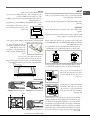
Fitting the appliance
The following precautions must be taken when installing the hob:
hob must be at least 600 mm from the edge of the hob.
If the hob is installed beneath a wall cabinet,
the latter must be situated at a minimum of
700 mm above the hob.
Before the installation remove the grids and burners from the hob and turn it
upside down, making sure you don’t damage the thermocouples and spark
plugs.
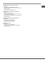
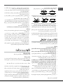
Apply the seals that come with the
appliance along the outer edges of
the hob to prevent any passage of air,
humidity and water (see Figure).
For proper application make sure the
surfaces to be sealed are clean, dry and
free of any grease/oil.
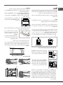
Fastening hooks are provided, allowing you to fasten the hob to tops that
are between 20 and 40 mm thick. To ensure the hob is securely fastened
to the top, we recommend you use all the hooks provided.
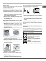
555
mm
475
mm
55
mm
Hook fastening diagram
Hooking position for top H=20mm Hooking position for top H=30mm
Front
Hooking position for top H=40mm Back
! Use the hooks contained in the “accessory pack”.
600mm min.
420mm min.
650mm min.

GB
11
be installed as insulation. This must be placed at a minimum distance of
20 mm from the lower part of the hob.
Ventilation
To ensure adequate ventilation, the back panel of the cabinet must be
removed. It is advisable to install the oven so that it rests on two strips of
mm (see diagrams).
560 mm.
45 mm.
Where a hob is installed above an oven without a forced ventilation cooling
system, adequate ventilation must be provided inside the cabinet by means
Electrical connection
Hobs equipped with a three-pole power supply cable are designed to operate
with alternating current at the voltage and frequency indicated on the data
plate (this is located on the lower part of the appliance). The earth wire in the
cable has a green and yellow cover. If the appliance is to be installed above
a built-in electric oven, the electrical connection of the hob and the oven must
be carried out separately, both for electrical safety purposes and to make
extracting the oven easier.
Connecting the supply cable to the mains
Install a standardised plug corresponding to the load indicated on the data
plate.
The appliance must be directly connected to the mains using an omnipolar
circuit-breaker with a minimum contact opening of 3 mm installed between the
appliance and the mains. The circuit-breaker must be suitable for the charge
indicated and must comply with current electrical regulations (the earthing
wire must not be interrupted by the circuit-breaker). The supply cable must
not come into contact with surfaces with temperatures higher than 50°C.
! The installer must ensure that the correct electrical connection has been
made and that it is compliant with safety regulations.
Before connecting to the power supply, make sure that:
indicated on the data plate.
incompatible with the plug, ask an authorised technician to replace it. Do
not use extension cords or multiple sockets.
! Once the appliance has been installed, the power supply cable and the
electrical socket must be easily accessible.
! The cable must not be bent or compressed.
! The cable must be checked regularly and replaced by authorised technicians
only (see Assistance).
! The manufacturer declines any liability should these safety measures not
be observed.
Gas connection
The appliance should be connected to the main gas supply or to a gas
cylinder in compliance with current national regulations. Before carrying out
the connection, make sure the cooker is compatible with the gas supply you
wish to use. If this is not the case, follow the instructions indicated in the
paragraph “Adapting to different types of gas.”
When using liquid gas from a cylinder, install a pressure regulator which
complies with current national regulations.
! Check that the pressure of the gas supply is consistent with the values indicated
Connection with a rigid pipe (copper or steel)
! Connection to the gas system must be carried out in such a way as not to
place any strain of any kind on the appliance.
Connecting a flexible jointless stainless steel pipe to a threaded
attachment
These pipes must be installed so that they are never longer than 2000 mm
when fully extended. Once connection has been carried out, make sure that
! Only use pipes and seals that comply with current national regulations.
Checking the tightness of the connection
!
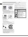
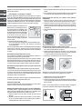
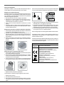
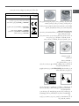
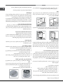
Adapting to different types of gas
To adapt the hob to a different type of gas other than default type (indicated
on the rating plate at the base of the hob or on the packaging), the burner
nozzles should be replaced as follows:
1. Remove the hob grids and slide the burners off their seats.
2. Unscrew the nozzles using a 7 mm socket spanner, and replace them
with nozzles for the new type of gas (see table 1 “Burner and nozzle
characteristics”).
3. Reassemble the parts following the above procedure in the reverse order.
indicating the new type of gas used. Sticker are available from any of our
Service Centres.
1. Remove the grids and slide the burners from their housings. The burner

12
GB
2. Unscrew the burers with a 7 mm wrench spanner. The internal burner
has a nozzle, the external burner has two (of the same size). Replace
the nozzle with models suited to the new type of gas (see table 1).
3. Replace all the components by repeating the steps in reverse order.
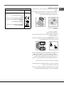
Replacing the Triple ring burner nozzles
1. Remove the pan supports and lift the burners out of their housing. The
burner consists of two separate parts (see pictures).
2. Unscrew the nozzles using a 7 mm socket spanner. Replace the nozzles
1). The two nozzles have the same hole diameter.
3. Replace all the components by completing the above operations in reverse
order.
Does not require adjusting.
2. Remove the knob and adjust the adjustment screw, which is positioned
! In the event of single-control DRDA (DCDR) burners, adjustment can be
performed by intervening on the 2 screws located near the tap pin (see picture).
Inner DRDA (DCDR)
burner adjustment
Total DRDA
(DCDR) burner
adjustment
alight, quickly change the position of the knob from minimum to maximum
5. Once the adjustment has been made, replace the seals on the by-passes
using sealing wax or a similar substance.
! If the appliance is connected to liquid gas, the regulation screw must be
fastened as tightly as possible.
!
indicating the new type of gas used. Stickers are available from any of our
Service Centres.
! Should the gas pressure used be different (or vary slightly) from the
inlet pipe (in order to comply with current national regulations).
Electrical
connections
DATA PLATE
see data plate
This appliance conforms to the following
European Economic Community directives:
- 2006/95/EC dated 12/12/06 (Low Voltage)
and subsequent amendments
- 2004/108/EC dated 15/12/04
(Electromagnetic Compatibility) and
subsequent amendments
- 93/68/EEC dated 22/07/93 and
subsequent amendments.
- 2009/142/EC dated 30/11/09 (Gas) and
subsequent amendments.
- 2012/19/EU and subsequent
amendments.

GB
13
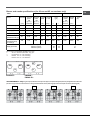
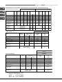
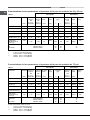
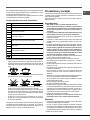
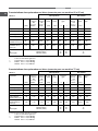
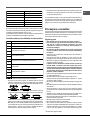
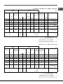
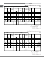
Table 1 Liquid Gas Natural Gas
Burner Diameter Thermal Thermal By-pass Nozzle Flow* Thermal Nozzle Flow*
power power 1/100 1/100 (g/h) power 1/100 (l/h)
kW kW kW
(p.c.s.*) (p.c.s.*) (p.c.s.*)
(mm) Reduced Nominal (mm) (mm) *** ** Nominal (mm)
Supply pressures
Nominal (mbar)
Minimum (mbar)
Maximum (mbar)
28-30
20
35
37
25
45
20
17
25
Reduced Fast (RR)
Semi Fast (S)
Auxiliary (A)
Triple Crown (TC)
100
75
55
130
0.70
0.40
0.40
1.50
2.60
1.65
1.00
3.30
39
28
28
61
80
64
50
65x2
189
120
73
240
186
118
71
236
2.60
1.65
1.00
3.60
122 (H)
96 (Y)
79 (6)
103x2
248
157
95
343
Burner and nozzle specifications (for 60 cm and 65 cm versions only)
(2) For dual-control DRD
A (DCDR) burner only
*
At 15°C and 1013,25 mbar - dry gas
**
Propane P.C.S. = 50.37 MJ/Kg
***
Butane P.C.S. = 49.47 MJ/Kg
Natural P.C.S. = 37.78 MJ/m³
Double Flame
(DCDR Internal) (2)
Double Flame
(DCDR External)
2 nozzle (2)
36
130
0.40
1.50
0.90
3.60
27
55
44
67x2
65
262
64
257
0.90
3.60
74
100x2
86
343
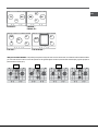
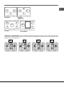
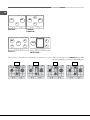
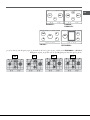
PK630RT
...
TC
DC
S
PK640R...
PK640.1R...
RR
DC
S
A
! For model PK 640.1... only: The grids may be positioned incorrectly. If this happens, the spokes will appear particularly misaligned and the intersection
OK KO !
KO !KO !

14
GB
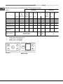
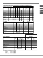
Table 1 Liquid Gas Natural Gas
Burner Diameter Thermal Thermal By-pass Nozzle Flow* Thermal Nozzle Flow*
power power 1/100 1/100 (g/h) power 1/100 (l/h)
kW kW kW
(p.c.s.*) (p.c.s.*) (p.c.s.*)
(mm) Reduced Nominal (mm) (mm) *** ** Nominal (mm)
Supply pressures
Nominal (mbar)
Minimum (mbar)
Maximum (mbar)
28-30
20
35
37
25
45
20
17
25
Reduced Fast (RR)
Semi Fast (S)
Auxiliary (A)
Triple Crown (TC)
Double Flame
(DCDR Internal) (2)
Double Flame
(DCDR External)
2 nozzle (2)
100
75
55
130
36
130
0.70
0.40
0.40
1.50
0.40
1.50
2.60
1.65
1.00
3.30
0.90
4.10
39
28
28
61
28
61
80
64
50
65x2
44
70x2
189
120
73
240
65
298
186
118
71
236
64
293
2.60
1.65
1.00
3.60
0.90
4.10
122 (H)
96 (Y)
79 (6)
103x2
74
110x2
248
157
95
343
86
390
Burner and nozzle specifications (for 75 cm versions only)
(2) For dual-control DRDA (DCDR) burner only
* At 15°C and 1013,25 mbar - dry gas
** Propane P.C.S. = 50.37 MJ/Kg
*** Butane P.C.S. = 49.47 MJ/Kg
Natural P.C.S. = 37.78 MJ/m³
PK741RQO...
DC
S
A
PK750T...
RR
TC
S
S
A

GB
15
Start-up and use
! The position of the corresponding gas burner or electric hotplate* is shown
on every knob.
Gas cooker hobs are equipped with discrete power adjustment that allows
system, gas hobs are also capable of guaranteeing the same cooking results
for each recipe, as the optimal power level for the desired type of cooking can
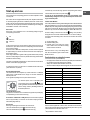
Gas burners
corresponding control knob:
Maximum
Minimum
To light one of the burners, hold a lit match or lighter near the burner and, at
the same time, press down and turn the corresponding knob anti-clockwise
to the maximum setting.
for approximately 2-3 seconds to allow the automatic device keeping the
When using models with an ignition button, light the desired burner pressing
down the corresponding knob as far as possible and turning it anticlockwise
towards the maximum setting.
!
at least 1 minute before trying to relight it.
To switch off the burner, turn the knob in a clockwise direction until it stops
The selected burner can be adjusted - by means of the knob - to 5 different
power levels. To shift between levels, simply turn the knob towards the
desired power level.
A click signals the passage from one power level to the other.
The selected power level is indicated by the
corresponding symbol (symbols
). The
uniform cooking results by facilitating selection of
the desired power level.
or independently (in case of dual-control only).
the knob should be pressed
automatically alight heats up.
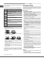
Dual control:
The knob marked with the symbol
controls the outer ring.
The knob marked with the symbol
controls the inner ring.
To activate any one of the two rings, press the corresponding knob and turn
it anti-clockwise to the maximum power setting
.
simultaneously setting the inner ring to minimum power and the outer
ring to maximum power.
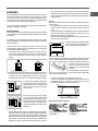
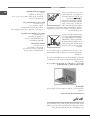
Ceramic Glass Module*
the letter ) or the cooking surface can be enlarged by turning on both and
. To turn only the circular element, simply turn the knob in the clockwise
direction to any one of the 12 available settings. To add the section, turn
the knob to setting 12 and then click it into the
setting. Then proceed by
turning the knob in the counter-clockwise direction to one of the 12 settings.
is turned on.
A. Circular heating zone;
C. Indicator light to show when the cooking
zone is above 60°C, even after the heating
element has been turned off.
When the knob is on any of the settings other
than “Off”, the Indicator Light for Ceramic Glass
Module comes on.
Practical advice on using the burners
do not extend beyond the bottom of the cookware.
Reduced Rapid (RR)
Semi Rapid (S)
Auxiliary (A)
Triple Crown (TC)
Double Flame (DCDR internal)
Double Flame (DCDR external)
24 - 26
16 - 20
10 - 14
24 - 26
10 - 14
24 - 26
Burner
Pans to be used on 60 - 65 cm hobs
Ø Cookware diameter (cm)
Reduced Rapid (RR)
Semi-Rapid (S)
Auxiliary (A)
Triple Crown (TC)
Double Flame (DCDR internal)
Double Flame (DCDR external)
24 - 26
16 - 20
10 - 14
24 - 26
10 - 14
26 - 28
Burner
Pans to be used on 75 cm hobs
Ø Cookware diameter (cm)
! On the models supplied with a reducer shelf, remember that this should be
casserole dishes with a diameter under 12 cm.
A
C
B
* Only available on certain models.

16
GB
To identify the type of burner, refer to the designs in the section entitled, “Burner
Practical Advise on Using the Ceramic Glass Module*
Set.
0
1
2
3
4
5
6
7
8
9
10
11
12
Radiant Burner
Off.
To melt butter and chocolate.
To heat liquids.
For creams and sauces.
For cooking at the boiling point.
For Roasts.
For boiling large pieces of meat.
For frying.
For utilising both cooking areas.
To obtain the best results from your hob:
perfectly.
fully, in order to use all the available heat.
guarantee correct adherence and long life, not only for the cooking zones
but also for the cookware itself.
concentration on gas burners may deform the base of the pan, causing it
not to adhere correctly.
heats up and rapidly reaches the maximum level, which could damage
the heating elements.
! There might be traces of grease left by the glue used to seal the glass
which should be removed before using the appliance with a mild cleaning
disappear quickly.
Precautions and tips
! This appliance has been designed and manufactured in compliance with
international safety standards. The following warnings are provided for safety
reasons and must be read carefully.
General safety
appear in the manual and on the serial number plate.
not intended for commercial or industrial use.
extremely dangerous to leave the appliance exposed to rain and storms.
feet.
in accordance with the instructions outlined in this booklet. Any other
use of the appliance (e.g. for heating the room) constitutes improper
use and is dangerous. The manufacturer may not be held liable for
use of the appliance.
come into contact with the hot parts of the oven.
covered.
” position when the appliance
is not in use.
do not pull on the cable.
the plug from the mains.
the appliance yourself. Repairs carried out by inexperienced persons may
cause injury or further malfunctioning of the appliance. Contact a Service
Centre (see Assistance).
hob in order to avoid accidental burns.
hotplates are still hot.
with reduced physical, sensory or mental capacities, by inexperienced
individuals or by anyone who is not familiar with the product. These
individuals should, at the very least, be supervised by someone who
assumes responsibility for their safety or receive preliminary instructions
relating to the operation of the appliance.
timer or separate remote-control system.
Disposal
the packaging may be reused.
* Only available on certain models.

GB
17
appliances must not be disposed of in the normal unsorted municipal
waste stream. Old appliances must be collected separately in order
to optimise the recovery and recycling of the materials they contain
and reduce the impact on human health and the environment.
The crossed out “wheeled bin” symbol on the product reminds you of your
obligation, that when you dispose of the appliance it must be separately
collected.
Consumers should contact their local authority or retailer for information
concerning the correct disposal of their old appliance.
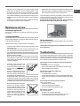
Maintenance and care
Switching the appliance off
Disconnect your appliance from the electricity supply before carrying out
any work on it.
Cleaning the appliance
! Do not use abrasive or corrosive detergents such as stain removers, anti-rust
products, powder detergents or sponges with abrasive surfaces: these may
scratch the surface beyond repair.
! Never use steam cleaners or pressure cleaners on the appliance.
absorbent kitchen roll.
warm water and soap and any burnt-on substances removed.
lighting devices should be cleaned frequently and the gas outlet holes
should be checked for blockages.
using a damp cloth to remove dust or food residues. The ceramic glass
surface should be cleaned regularly with a soultion of warm water and a
non-abrasive detergent.
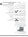
Periodically, special products will need
to be used to clean the surface. First,
remove all food buildup or grease with a
cleaning scraper, e.g.
(not
supplied).
Clean the cooking surface when it is still
warm with a suitable cleaning product
(such as the one in the Solutions product
line available from any After-Sales Service
Centre) and paper towels. Then rub with a damp cloth and dry. Aluminum
foil, plastic items, objects made of synthetic material, sugar or foods with
a high sugar content that have melted onto the surface must be removed
immediatley with a scraper while the cooking surface is still hot.
Special cleaning products for ceramic glass
surfaces form a transparent protective
protects the surface from damage caused
by food with a high sugar content. Do
not use abrasive sponges or cleaning
products under any circumstances. This
holds true for chemically aggressive
cleaners, like oven sprays and stain
removers.
surface for a long time, or by aggressive detergents containing phosphorus.
After cleaning, rinse and dry any remaining drops of water.
! It is not necessary to remove the pan supports in order to clean the hob
surface. Thanks to the support system, simply lift and hold the pan supports
or rotate them until they rest against a rear support.
otherwise the rubber plugs on the glass may be damaged.
Gas tap maintenance
the tap must be replaced.
!
by the manufacturer.
Troubleshooting
It may happen that the appliance does not function properly or at all. Before
calling the service centre for assistance, check if anything can be done. First,
check to see that there are no interruptions in the gas and electrical supplies,
and, in particular, that the gas valves for the mains are open.
Check whether:
Check to make sure that:
device.
The burner does not remain lit when set to minimum.
Check to make sure that:
The cookware is unstable.
Check to make sure that:

18
FR
LU
BE
NL
Installation
! Conservez ce mode d’emploi pour pouvoir le consulter à tout moment.
l’appareil pour informer le nouveau propriétaire sur son fonctionnement et lui
fournir les conseils correspondants.
! Lisez attentivement les instructions : elles contiennent des conseils
importants sur l’installation, l’utilisation et la sécurité de votre appareil
Les appareils réglés en usine pour (voir la plaquette d’immatriculation et la
plaquette prédisposition gaz de l’appareil):
Un ultérieur réglage n’est donc pas nécessaire.
Conditions réglementaires d’installation (Pour la France)
Le raccordement gaz devra être fait par un technicien qui assurera la bonne
alimentation en gaz et le meilleur réglage de la combustion des brûleurs. Ces
opérations d’installation, quoique simples, sont délicates et primordiales pour
que votre table de cuisson vous rende le meilleur service. L’installation doit
être effectuée conformément aux textes réglementaires et règles de l’art en
vigueur, notamment:
l’intérieur des bâtiments d’habitation et de leurs dépendances.
Positionnement
! Les emballages ne sont pas des jouets pour enfants, il faut les mettre au
rebut en respectant la réglementation sur le tri sélectif des déchets (voir
Précautions et conseils).
! L’installation doit être effectuée par un professionnel du secteur
conformément aux instructions du fabricant. Une mauvaise installation peut
causer des dommages à des personnes, des animaux ou des biens.
! Cet appareil peut être installé et fonctionner seulement dans des locaux qui
sont aérés en permanence, selon les prescriptions des Normes:
Il faut observer les conditions suivantes:
de combustion, réalisé au moyen d’une hotte ou par ventilateur électrique
qui entre automatiquement en fonction dès que l’on allume l’appareil.
En cas de cheminée ou conduit de fumée ramifié
(réservé aux appareils de cuisson)
Directement
à l'externe
doit pas être inférieur à 2 m
3
/h par kW de puissance installée.
Le système peut être réalisé en prélevant
l’air directement de l’extérieur du bâtiment au
moyen d’un conduit d’au moins100 cm
2
de
section utile qui ne risque pas d’être bouché
accidentellement.
Ou, de manière indirecte depuis des
locaux adjacents et équipés d’un conduit
de ventilation avec l’extérieur comme
susmentionné; ces locaux ne doivent pas
être des parties communes du bâtiment, des
chambres à coucher ou des locaux à risque
d’incendie.
(Pour la France et la Belgique)
lourds que l’air, se déposent et stagnent vers le bas. Les locaux qui
contiennent donc des bouteilles de G.P.L doivent prévoir des ouvertures
de fuites accidentelles. Les bouteilles de GPL, qu’elles soient vides ou
partiellement pleines, ne devront donc pas être installées ou entreposées
dans des locaux qui se trouvent au dessous du niveau du sol (caves etc.).
Il est opportun de n’entreposer dans le local que la bouteille que vous êtes
en train d’utiliser, placée de façon à ne pas être sujette à l’action directe de
sources de chaleur (fours, feux de bois, poêles etc.) qui peuvent atteindre
des températures dépassant 50°C.
Encastrement
Pour une installation correcte de la table de cuisson, il faut se conformer aux
instructions suivantes :
cuisson, doivent être placés à au moins 600 mm du bord du plan.
dans leur notice d’installation et à au moins 650 mm de distance (voir
sous un élément haut, ce dernier devra être
monté à au moins 700 mm de distance du
plan.
Avant de procéder à l’installation, enlever les grilles et les brûleurs du plan
de cuisson et renverser celui-ci en veillant à ce que les thermocouples et les
bougies ne soient pas endommagés.
Appliquer les joints fournis avec
l’appareil sur les bords extérieurs du
plan de cuisson pour empêcher le
passage de l’air, de l’humidité et de l’eau
Pour une application correcte, s’assurer
que les surfaces à sceller sont propres,
sèches et sans traces de graisses/huiles.
A
Exemples d'ouverture
de ventilation
pour l'air comburant
Agrandissement de la fissure
entre la porte et le sol
Local
adjacent
Local à
ventiler
600mm min.
420mm min.
650mm min.

FR
BE
LU
NL
19
fournis.
555
mm
475
mm
55
mm
Position du crochet pour top Position du crochet pour top
H=20mm H=30mm
Devant
Position du crochet pour top Derrière
H=40mm
! Utilisez tous les crochets compris dans le “sachet accessoires”
un panneau d’isolation en bois. Il faut le monter à au moins 20 mm de
distance du bord inférieur de la table.
Aération
Pour garantir une bonne aération, la cavité d’encastrement doit être dépourvue
de paroi arrière. Il est conseillé d’installer le four de manière à ce qu’il repose
sur deux cales en bois ou bien sur un plan d’appui continu qui ait une découpe
560 mm.
45 mm.
de refroidissement forcée, il faudra prévoir des prises d’air d’entrée et de
Raccordement électrique
Les tables munies d’un cordon d’alimentation tripolaire, sont prévues pour un
fonctionnement à courant alternatif à la tension et à la fréquence d’alimentation
indiquées sur la plaquette des caractéristiques (placée sous la table de
au-dessus d’un four à encastrer, la connexion électrique de la table et celle
du four doivent être effectuées séparément, pour des questions de sécurité
Branchement du câble d’alimentation au réseau électrique
Montez sur le câble une prise normalisée adaptée à la charge indiquée sur
l’étiquette des caractéristiques.
et le réseau un interrupteur à coupure omnipolaire ayant au moins 3 mm
d’écartement entre les contacts, dimensionné à la charge et conforme aux
Le câble d’alimentation ne doit atteindre, en aucun point, des températures
dépassant de 50°C la température ambiante.
! L’installateur est responsable du bon raccordement électrique de l’appareil
et du respect des normes de sécurité.
Avant de procéder au branchement, assurez-vous que :
indiquée sur la plaquette signalétique;
la plaquette signalétique;
! Après installation de l’appareil, le câble électrique et la prise de courant
doivent être facilement accessibles
! Le câble ne doit être ni plié ni excessivement écrasé.
! Il doit être contrôlé périodiquement et ne peut être remplacé que par un
technicien agréé (voir Assistance).
! Nous déclinons toute responsabilité en cas de non respect des normes
énumérées ci-dessus.
Raccordement gaz
Pour la France
Raccorder l’appareil à la bouteille ou à la canalisation du gaz conformément
bien réglé pour le type de gaz d’alimentation utilisé. Dans le cas contraire,
effectuer les opérations décrites au paragraphe “Adaptation aux différents
types de gaz”. Pour l’alimentation en gaz liquide, utiliser des régulateurs de
pression conformes aux Normes en vigueur.
! Pour un fonctionnement en toute sécurité, pour l’emploi correct de l’énergie et

20
FR
LU
BE
NL
respecte bien les valeurs indiquées dans le tableau 1 “Caractéristiques des
brûleurs et des injecteurs”.
Pour la Belgique - le Luxembourg - la Hollande
Raccorder l’appareil à la canalisation du gaz conformément aux normes en
l’appareil est bien réglé pour le type de gaz d’alimentation utilisé. Dans le cas
contraire, (pour la Belgique) effectuer les opérations décrites au paragraphe
“Adaptation aux différents types de gaz”. Pour l’alimentation en gaz liquide,
utiliser des régulateurs de pression conformes aux Normes en vigueur.
Pour relier l’appareil à la canalisation du gaz
le Luxembourg et I2L pour la Hollande, il faut
avant tout installer le raccord “R” (disponible
sur demande auprès du Service d’Assistance
Technique Ariston) avec son étanchéité “G”
sur le raccord en forme de “L” situé sur le
avec pas 1/2 gaz.
Le raccordement doit être réalisé au moyen:
- ou d’un tuyau rigide (pour la Belgique selon les Normes NBN D51-003
marqué A.G.B); il devra être installé de manière à pouvoir facilement le
manoeuvrer. Pour le Luxembourg et la Hollande selon les Normes Nationales
en vigueur.
Raccordement par tuyau rigide (cuivre ou acier)
! Le raccordement à l’installation de gaz doit être effectué de manière à ce
que l’appareil ne subisse aucun type de contrainte.
La rampe d’alimentation de l’appareil est munie d’un raccord en “L” orientable
dont l’étanchéité est assurée par un joint. S’il vous faut inverser le raccord, vous
devez obligatoirement remplacer le joint d’étanchéité (fourni avec l’appareil).
La mise en œuvre de ces tuyaux doit être effectuée de façon à ce que, même
au maximum de leur extension, ils ne dépassent pas 2000 mm de long. Après
à des parties mobiles et n’est pas écrasé.
! N’utilisez que des tuyaux conformes et des joints d’étanchéité conformes
aux textes réglementaires applicables dans le pays.
!
Adaptation aux différents types de gaz (pour la France et la Belgique)
Pour adapter la table à un type de gaz autre que celui pour lequel elle a été
changer les injecteurs des brûleurs en procédant comme suit :
logement.
2. Dévissez les injecteurs à l’aide d’une clé à tube de 7 mm et remplacez-
les par les injecteurs adaptés au nouveau type de gaz (voir tableau 1
“Caractéristiques des brûleurs et des injecteurs”).
L
G
R
3. Remontez les différentes parties en effectuant les opérations dans le sens
inverse.
au nouveau gaz utilisé, disponible dans nos Services Après-vente.
indépendantes
2. Dévissez les injecteurs à l’aide d’une clef en tube de 7 mm. Le brûleur
intérieur a un injecteur, le brûleur extérieur en a deux (de même dimension).
Remplacez les injecteurs par d’autres appropriés au nouveau type de gaz
(voir tableau 1).
3. Remontez les différentes parties en effectuant les opérations dans le sens
inverse.
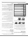
Remplacement des injecteurs du brûleur Triple couronne
1. Retirer les grilles et sortir les brûleurs de leurs logements. Le brûleur est
2. Dévisser les injecteurs à l’aide d’une clé à tube de 7 mm. Remplacer les
injecteurs par d’autres appropriés au nouveau type de gaz (voir tableau
1). Les deux injecteurs sont percés des mêmes trous.
3. Remonter les composants dans le sens inverse du démontage.
Réglage de l’air primaire des brûleurs (pour la France et la Belgique)
Les brûleurs ne nécessitent d’aucun réglage de l’air primaire.
1. Placez le robinet sur la position de minima;
2. Déposez la manette et tournez la vis de réglage positionnée à l’intérieur
ou sur le côté de la tige du robinet jusqu’à ce que vous obteniez une petite
! Dans le cas du brûleur DCDR mono commande, effectuer le réglage au
Réglage
DCDR intérieur
Réglage
DCDR total
A página está carregando...
A página está carregando...
A página está carregando...
A página está carregando...
A página está carregando...
A página está carregando...
A página está carregando...
A página está carregando...
A página está carregando...
A página está carregando...
A página está carregando...
A página está carregando...
A página está carregando...
A página está carregando...
A página está carregando...
A página está carregando...
A página está carregando...
A página está carregando...
A página está carregando...
A página está carregando...
A página está carregando...
A página está carregando...
A página está carregando...
A página está carregando...
A página está carregando...
A página está carregando...
A página está carregando...
A página está carregando...
A página está carregando...
A página está carregando...
A página está carregando...
A página está carregando...
A página está carregando...
A página está carregando...
A página está carregando...
A página está carregando...
A página está carregando...
A página está carregando...
A página está carregando...
A página está carregando...
A página está carregando...
A página está carregando...
A página está carregando...
A página está carregando...
-
 1
1
-
 2
2
-
 3
3
-
 4
4
-
 5
5
-
 6
6
-
 7
7
-
 8
8
-
 9
9
-
 10
10
-
 11
11
-
 12
12
-
 13
13
-
 14
14
-
 15
15
-
 16
16
-
 17
17
-
 18
18
-
 19
19
-
 20
20
-
 21
21
-
 22
22
-
 23
23
-
 24
24
-
 25
25
-
 26
26
-
 27
27
-
 28
28
-
 29
29
-
 30
30
-
 31
31
-
 32
32
-
 33
33
-
 34
34
-
 35
35
-
 36
36
-
 37
37
-
 38
38
-
 39
39
-
 40
40
-
 41
41
-
 42
42
-
 43
43
-
 44
44
-
 45
45
-
 46
46
-
 47
47
-
 48
48
-
 49
49
-
 50
50
-
 51
51
-
 52
52
-
 53
53
-
 54
54
-
 55
55
-
 56
56
-
 57
57
-
 58
58
-
 59
59
-
 60
60
-
 61
61
-
 62
62
-
 63
63
-
 64
64


Ariston PK 630 RT GH Manual do proprietário
- Tipo
- Manual do proprietário
em outras línguas
Artigos relacionados
-
Ariston PK 640 R GH Guia de usuario
-
-
-
-
Whirlpool PKL 751 T/IX/A Guia de usuario
-
-
Ariston PC 640 N T GH Guia de usuario
-
Ariston PC 640 N T GH Instruções de operação
-
-