
© 2022 Carrier. All rights reserved. 1 / 26 P/N 03-0210-501-0300-03 • ISS 04NOV22
DM3000 Series Intelligent Addressable Manual
Call Point Installation Sheet
EN DE ES FR IT NL PL PT
1
2
3
4
5
6

2 / 26 P/N 03-0210-501-0300-03 • ISS 04NOV22
EN: Installation Sheet
Description
The DM3000 Series Intelligent Addressable Manual Call Point
is designed for indoor use and supports the Aritech 2000
protocol.
All units are supplied with a resettable element – this can be
replaced with a breakable element, if required (order number
N-MC-FE). See “Replacing the resettable element” on page 3.
The series includes the following models.
Model
Description
DM3010
R [1] Red intelligent addressable manual call point
DM3
110R [1] Red intelligent addressable manual call point
with integrated short circuit isolator
[1] Also available in blue, green, orange, white, and yellow.
Figures
Figure
1: Mounting holes and dimensions
Figure
2: Front assembly terminal block and DIP switch
Figure 3: Unlocking the front cover
Figure
4: Removing the front cover
Figure 5: Removing the resettable element
Figure
6: Replacing the front cover
Installation
Caution: This product must be installed and maintained by
qualified personnel adhering to all local or national installation
requirements and any other applicable regulations.
Addressing
Set the device address before installation using the DIP switch
on the back of the front assembly (see Figure 2).
The address range is 001-128. See the table on the last page
of this publication for DIP switch positions for each address.
Note: If you change the device address after installation, you
must disconnect the device from the loop power for at least
one second and then reconnect it for the new address to be
recognised.
Installation
The manual call point can be surface mounted or recess
mounted.
For surface mounting, order one of the backboxes shown in
the table below.
Model
Description
N
-MC-BB-R Red backbox
N
-MC-BB-U Blue backbox
N
-MC-BB-G Green backbox
Model
Description
N
-MC-BB-O Orange backbox
N
-MC-BB-W White backbox
N
-MC-BB-Y Yellow backbox
For recess mounting, order one of the recess adaptors and (if
required) trim skirts shown in the table below.
Model
Description
N
-MC-AFM-R Red recess adaptor
N
-MC-AFMG-R Red recess adaptor with fork grips
N
-MC-S-R Red trim skirt
N
-MC-AFM-G Green recess adaptor
N
-MC-S-G Green trim skirt
Remember to remove the protective dust cover after
commissioning.
Note: The dust cover may also be used to indicate when the
unit is not operational (for example, before commissioning,
during maintenance, when disabled, etc.)
To surface mount the manual call point:
1. Fix the backbox onto the wall using 4 × M4 screws (not
supplied) and feed the loop cable through the selected
cable knockouts.
Depending on your installation requirements, the backbox
can be installed with two cable knockouts at the top and
one at the bottom or with one cable knockout at the top
and two at the bottom.
See Figure 1 for the location of the mounting holes.
2. Connect loop cable to the supplied terminal block, and
then plug the terminal block into the PCB connector on the
back of the front assembly (see Figure 2).
Use the supplied cable link to test cable continuity before
the terminal block is plugged into the PCB connector on
the back of the front assembly.
See “Wiring” on page 3 for terminal block connections and
loop cable specifications.
3. Unlock and remove the front cover, and then remove the
resettable element.
To unlock the front cover, insert the key and turn it
clockwise (two clicks), then pull the cover outwards from
the bottom to remove it (see Figure 3 and Figure 4).
To remove the resettable element, push the element up,
and then pull it out (see Figure 5).
4. Fix the front assembly to the backbox using the 2 screws
supplied with the unit (located in the backbox).
5. Replace the resettable element (or add the breakable
element, if required), and then replace the front cover (see
Figure 6).
Turn the key anticlockwise (two clicks) to lock the cover,
and then remove the key.
Finally, test the manual call point (see “Testing” on page 3).

P/N 03-0210-501-0300-03 • ISS 04NOV22 3 / 26
Wiring
For optimal system performance, use 0.13 to 3.31 mm² (0.40
to 2.05 mm) twisted-pair cable with a maximum length of 2 km.
Wire the unit as described below. Observe the indicated
polarity.
Terminal
Description
A
+ Positive line (+)
B
+ Positive line (+)
A
– Negative line (–)
B
– Negative line (–)
Device status
The device status is indicated by two colour changing LEDs on
the front of the unit, as shown in the table below.
State
Indication
Alarm
Steady red LEDs [1]
Isolation active
Steady yellow LEDs [2]
Fault
Flashing yellow LEDs
Communicating
Flashing green LEDs
[1] This may also indicate an active Locate Device command from the
control panel.
[2] DM3110 models only.
Maintenance and testing
Maintenance
The unit should be maintained and tested according to local or
national requirements and any other applicable regulations. Do
not modify internal wiring or circuitry.
Testing
To activate an alarm, push the resettable element or turn the
key clockwise (one click). To reset the device, turn the key
anticlockwise (one click). Reset the control panel after testing.
Replacing the resettable element
Replace the resettable element (or add the breakable element)
as follows:
1. Unlock and remove the front cover as described in
“Installation” on page 2.
2. Push the element up, and then pull it out (see Figure 5).
3. Replace the resettable element (or add the breakable
element, if required).
4. Replace the front cover.
Analogue values
Analogue values for diagnosing and troubleshooting device
status are shown in the table below.
Value
Device Status
32
Normal
128
Alarm
Specifications
Electrical
Operating voltage
17 to 38 VDC
Current
consumption
Standby
DM3010
DM3110
Alarm
DM3010
DM3110
180 µA
200 µA
2.8 mA
2.8 mA
Isolation
The following isolation specifications apply to DM3110 models
with an integrated short circuit isolator.
Current consumption
(isolation
active
)
1.5 mA
Isolation
voltage
Minimum
Maximum
14 VDC
15.5 VDC
Reconnect voltage
Minimum
Maximum
14 VDC
15.5 VDC
Rated current
Continuous (switch closed)
Switching (short circuit)
1 A
1 A
Leakage current
1 mA max.
Series impedance
0.06 Ω max.
Number of isolators per loop
128 max.
Number of devices between
isolators
32 max.
Mechanical and environmental
IP rating
IP41
Bac
kbox cable knockouts
Back
Top/bottom [1]
1 × Ø 20 mm
1 × Ø 25 mm
2 × Ø 20 mm
Wire size
Minimum
Maximum
0.13 mm² (0.40 mm)
3.31 mm² (2.05 mm)
Operating environment
Operating temperature
Storage temperature
Relative humidity
−25 to +72°C
−25 to +72°C
10 to 95% (noncondensing)
Colour
Red
Blue
Green
Orange
White
Yellow
RAL3028
RAL5005
RAL6024
RAL2008
RAL9003
RAL1003
Material
Body
Contacts
ABS, PC, PMMA, POM
Nickel plated H59, tin plated
QSn6.5-0.1, tin plated H65
Weight
Without backbox
With backbox [2]
110 g
165 g

4 / 26 P/N 03-0210-501-0300-03 • ISS 04NOV22
Dimensions
Without backbox
With backbox [2]
87 × 87× 26 mm
87 × 87× 57 mm
[1]
Top/bottom location subject to installation orientation.
[2] Backbox not supplied.
Regulatory information
This section provides a summary on the declared performance
according to the Construction Products Regulation
(EU) 305/2011 and Delegated Regulations (EU) 157/2014 and
(EU) 574/2014.
For detailed information, see the product Declaration of
Performance (available at firesecurityproducts.com).
Conformity
Notified
/Approved body 0370
Manufacturer
Carrier Safety System (Hebei) Co. Ltd.,
80 Changjiang East Road, QETDZ,
Qinhuangdao 066004, Hebei, China.
Authorized EU manufacturing
representative:
Carrier Fire & Security B.V.,
Kelvinstraat 7, 6003 DH Weert,
Netherlands.
Year of first CE marking
2022
Declaration of
Performance number
[1]
DM3010
DM3110
03-0210-360-1083
03-0210-360-1093
EN 54
[1] EN 54-11 Type A (Indoor Use)
EN 54-17:2005
Product identification
[1] DM3010R, DM3110R, DM3010RS06,
DM3110RS06, DM3010RS18,
DM3110RS18, DM3010RS27,
DM3110RS27, DM3010RSCH,
DM3110RSCH, DM3010RSCL,
DM3110RSCL
Intended use
See the product Declaration of
Performance
Declared performance
See the product Declaration of
Performance
2012/19/EU (WEEE Directive): Products
marked with this symbol cannot be
disposed of as unsorted municipal waste
in the European Union. For proper
recycling, return this product to your local
supplier upon the purchase of equivalent
new equipment, or dispose of it at
designated collection points. For more
information see: recyclethis.info.
[1] The Declaration of Performance only covers red manual call points.
Only red manual call points are covered by EN 54-11 and EN 54-17.
Contact information and product
documentation
For contact information or to download the latest product
documentation, visit firesecurityproducts.com.
Product warnings and disclaimers
THESE PRODUCTS ARE INTENDED FOR SALE TO AND
INSTALLATION BY QUALIFIED PROFESSIONALS.
CARRIER FIRE & SECURITY B.V. CANNOT PROVIDE ANY
ASSURANCE THAT ANY PERSON OR ENTITY BUYING ITS
PRODUCTS, INCLUDING ANY “AUTHORIZED DEALER” OR
“AUTHORIZED RESELLER”, IS PROPERLY TRAINED OR
EXPERIENCED TO CORRECTLY INSTALL FIRE AND
SECURITY RELATED PRODUCTS.
For more information on warranty disclaimers
and product safety information, please check
https://firesecurityproducts.com/policy/product
-
warning/ or scan the QR code:
DE: Installationsanweisungen
Beschreibung
Der intelligente adressierbare
Druckknopfmelder/Handfeuermelder der Serie DM3000 ist für
den Innenbereich vorgesehen und unterstützt das Protokoll
Aritech 2000.
Alle Geräte verfügen standardmäßig über ein rücksetzbares
Element, das ggf. durch ein unterbrechbares/zerbrechbares
Element ersetzt werden kann (Bestellnummer N-MC-FE).
Siehe „Ersetzen des rücksetzbaren Elements“ auf Seite 6.
Die Serie umfasst die folgenden Modelle.
Modell
Beschreibung
DM3010R [1]
Roter intelligenter adressierbarer
Druckknopfmelder
DM3110R [1]
Roter intelligenter adressierbarer
Druckknopfmelder mit integriertem
Kurzschlussisolator
[1] Auch in Blau, Grün, Orange, Weiß und Gelb erhältlich.
Abbildungen
Abbildung
1: Montagebohrungen und Abmessungen
Abbildung
2: Anschlussklemmleiste vordere Baugruppe und DIP
Schalter
Abbildung
3: Entriegeln der Vorderabdeckung
Abbildung
4: Entfernen der Vorderabdeckung
Abbildung
5: Entfernen des rücksetzbaren Elements
Abbildung
6: Austauschen der Vorderabdeckung

P/N 03-0210-501-0300-03 • ISS 04NOV22 5 / 26
Installation
Warnung: Dieses Produkt muss von qualifiziertem Personal
gemäß allen vor Ort bzw. landesweit geltenden
Installationsanforderungen und behördlichen Vorschriften
installiert und gewartet werden.
Adressierung
Stellen Sie die Melderadresse vor der Installation mit dem DIP
Schalter auf der Rückseite der vorderen Baugruppe ein (siehe
Abbildung 2).
Der Adressbereich ist 001-128. In der Tabelle auf der letzten
Seite dieser Veröffentlichung finden Sie die Positionen des DIP
Schalters für jede Adresse.
Hinweis: Wenn Sie die Melderadresse nach der Installation
ändern, müssen Sie den Melder mindestens eine Sekunde
lang von der Versorgung der Ringleitung trennen und dann
wieder anschließen, damit die neue Adresse erkannt wird.
Installation
Der Druckknopfmelder kann auf Putz oder bündig montiert
werden.
Bestellen Sie für die Aufputzmontage eines der in der
folgenden Tabelle aufgeführten Aufputzgehäuse.
Modell
Beschreibung
N
-MC-BB-R Rotes Aufputzgehäuse
N
-MC-BB-U Blaues Aufputzgehäuse
N
-MC-BB-G Grünes Aufputzgehäuse
N
-MC-BB-O Oranges Aufputzgehäuse
N
-MC-BB-W Weißes Aufputzgehäuse
N
-MC-BB-Y Gelbes Aufputzgehäuse
Bestellen Sie für die bündige Montage einen entsprechenden
Adapter und (falls erforderlich) UP-Rahmen-Adapter, die in der
folgenden Tabelle aufgeführt sind.
Modell
Beschreibung
N
-MC-AFM-R Rote UP-Adapterplatte
N
-MC-AFMG-R Rote UP-Adapterplatte mit Griffgabeln
N
-MC-S-R Roter umlaufender UP-Rahmen-Adapter
N
-MC-AFM-G Grüne UP-Adapterplatte
N
-MC-S-G Grüner umlaufender UP-Rahmen-Adapter
Denken Sie daran, die Staubschutzabdeckung nach der
Inbetriebnahme zu entfernen.
Hinweis: Durch Anbringen der Staubschutzabdeckung kann
auch darauf hingewiesen werden, dass das Gerät nicht
betriebsbereit ist (z. B. vor der Inbetriebnahme, während der
Wartung, bei Deaktivierung usw.).
So montieren Sie den Druckknopfmelder auf Putz:
1. Befestigen Sie das Aufputzgehäuse mit Schrauben
(4 × M4, nicht im Lieferumfang enthalten) an der Wand
und führen Sie das Ringleitungskabel durch die
passenden Kabelausstanzungen.
Abhängig von Ihren Installationsanforderungen kann das
Aufputzgehäuse mit zwei Kabelausstanzungen oben und
einer unten oder mit einer Kabelausstanzung oben und
zwei unten montiert werden.
Die Lage der Montagebohrungen ist in Abbildung 1
dargestellt.
2. Schließen Sie das Ringleitungskabel am beiliegenden
Anschlussklemmblock an und stecken Sie den
Anschlussklemmblock anschließend in den
Steckverbinder der Leiterplatte auf der Rückseite der
vorderen Baugruppe (siehe Abbildung 2).
Verwenden Sie die mitgelieferte Kabelverbindung, um den
Kabeldurchgang zu testen, bevor der
Anschlussklemmblock in den Steckverbinder der
Leiterplatte auf der Rückseite der vorderen Baugruppe
gesteckt wird.
Informationen zu den Anschlüssen des
Anschlussklemmblocks sowie die Spezifikationen für das
Ringleitungskabel finden Sie unter „Verkabelung“ weiter
unten.
3. Entriegeln und entfernen Sie die Vorderabdeckung und
entfernen Sie dann das rücksetzbare Element.
Setzen Sie zum Entriegeln der Vorderabdeckung den
Schlüssel ein und drehen Sie diesen im Uhrzeigersinn
(zwei Klicks). Ziehen Sie dann die Abdeckung von unten
nach außen, um diese zu entfernen (siehe Abbildung 3
und Abbildung 4).
Zum Entfernen des rücksetzbaren Elements drücken Sie
das Element nach oben und ziehen es anschließend
heraus (siehe Abbildung 5).
4. Befestigen Sie die vordere Baugruppe mithilfe der 2 mit
dem Gerät gelieferten Schrauben (im Aufputzgehäuse) am
Aufputzgehäuse.
5. Setzen Sie das rücksetzbare Element wieder ein (oder
installieren Sie ggf. das unterbrechbare Element) und
bringen Sie dann die Vorderabdeckung wieder an (siehe
Abbildung 6).
Drehen Sie den Schlüssel gegen den Uhrzeigersinn (zwei
Klicks), um die Abdeckung zu verriegeln, und ziehen Sie
dann den Schlüssel ab.
Testen Sie abschließend den Druckknopfmelder (siehe
„Testen“ weiter unten).

6 / 26 P/N 03-0210-501-0300-03 • ISS 04NOV22
Verkabelung
Verwenden Sie für eine optimale Systemleistung Twisted-Pair-
Kabel mit 0,13 bis 3,31 mm² (0,40 bis 2,05 mm) und einer
maximalen Länge von 2 km.
Verkabeln Sie das Gerät wie nachfolgend beschrieben. Achten
Sie auf die angegebene Polarität.
Anschlusskle
mme
Beschreibung
A+
Plusleitung (+)
B+
Plusleitung (+)
A
– Minusleitung (–)
B
– Minusleitung (–)
Melderstatus
Der Melderstatus wird durch zwei die Farbe wechselnde LEDs
an der Gerätevorderseite angezeigt (siehe folgende Tabelle).
Status
Anzeige
Alarm
Durchgehend rot leuchtende LEDs [1]
Isolation aktiv
Durchgehend gelb leuchtende LEDs [2]
Störung
Gelb blinkende LEDs
Kommunikation
läuft
Grün blinkende LEDs
[1] Dies kann auch bedeuten, dass über die Brandmelderzentrale der
Befehl „Lokalisiere Melder“ aktiv ist.
[2] Nur DM3110-Modelle.
Wartung und Testen
Wartung
Das Gerät sollte gemäß den vor Ort bzw. landesweit geltenden
Anforderungen und behördlichen Vorschriften gewartet und
getestet werden. Interne Verdrahtungen oder Schaltkreise
dürfen nicht verändert werden.
Testen
Drücken Sie zum Aktivieren eines Alarms das rücksetzbare
Element oder drehen Sie den Schlüssel im Uhrzeigersinn (ein
Klick). Wenn Sie das Gerät zurücksetzen möchten, drehen Sie
den Schlüssel gegen den Uhrzeigersinn (ein Klick). Setzen Sie
die Brandmelderzentrale nach dem Testen zurück.
Ersetzen des rücksetzbaren Elements
Gehen Sie zum Ersetzen des rücksetzbaren Elements (bzw.
zum Installieren des unterbrechbaren Elements) wie folgt vor:
1. Entriegeln und entfernen Sie die Vorderabdeckung, wie
unter „Installation“ auf Seite 5 beschrieben.
2. Drücken Sie das Element nach oben und ziehen Sie es
anschließend heraus (siehe Abbildung 5).
3. Ersetzen Sie das rücksetzbare Element (bzw. installieren
Sie das unterbrechbare Element).
4. Setzen Sie die Vorderabdeckung wieder ein.
Analoge Werte
In der folgenden Tabelle sind analoge Werte für die Diagnose
und Fehlerbehebung des Melderstatus aufgeführt.
Wert
Melderstatus
32
Normal
128
Alarm
Technische Daten
Elektrik
Betriebsspannung
17 bis 38 V DC
Stromaufnahme
Ruhezustand
DM3010
DM3110
Alarm
DM3010
DM3110
180 µA
200 µA
2,8 mA
2,8 mA
Isolation
Die folgenden technischen Daten zur Isolation gelten für
DM3110-Modelle mit integriertem Kurzschlussisolator.
Stromaufnahme (Isolation aktiv)
1,5 mA
Isolationsspannung
Minimum
Maximum
14 V DC
15,5 V DC
Wiederanschlussspannung
Minimum
Maximum
14 V DC
15,5 V DC
Nennstrom
Kontinuierlich (Wechsler
geschlossen)
Schalten (Kurzschluss)
1 A
1 A
Leckstrom
max. 1 mA
Impedanz der Serie
max. 0.06 Ω
Anzahl von Isolatoren pro
Ringleitung
max. 128
Maximale Anzahl von Meldern
zwischen Isolatoren
max. 32
Maße und Umgebungsbedingungen
IP
Nennbelastung IP41
Aufputzgehäuse
-
Kabelausstanzungen
Hinten
Oben/unten [1]
1 × Ø 20 mm
1 × Ø 25 mm
2 × Ø 20 mm
Drahtstärke
Minimum
Maximum
0,13 mm² (0,40 mm)
3,31 mm² (2,05 mm)
Betriebsumgebung
Betriebstemperatur
Lagertemperatur
Relative Feuchtigkeit
−25 bis +72 °C
−25 bis +72 °C
10 bis 95 % (nicht kondensierend)

P/N 03-0210-501-0300-03 • ISS 04NOV22 7 / 26
Farbe
Rot
Blau
Grün
Orange
Weiß
Gelb
RAL3028
RAL5005
RAL6024
RAL2008
RAL9003
RAL1003
Material
Gehäuse
Kontakte
ABS, PC, PMMA, POM
H59 vernickelt, QSn6.5-0.1
verzinnt, H65 verzinnt
Gewicht
Ohne Aufputzgehäuse
Mit Aufputzgehäuse [2]
110 g
165 g
Abmessungen
Ohne Aufputzgehäuse
Mit Aufputzgehäuse [2]
87 × 87× 26 mm
87 × 87× 57 mm
[1] Oben/unten je nach Einbaulage
.
[2] Aufputzgehäuse nicht im Lieferumfang enthalten.
Regulatorische Informationen
Dieser Abschnitt enthält eine Zusammenfassung der erklärten
Leistung gemäß der Verordnung zu Bauprodukten
(EU) 305/2011 und den delegierten Verordnungen
(EU) 157/2014 und (EU) 574/2014.
Ausführliche Informationen finden Sie in der
Leistungserklärung des Produkts (verfügbar auf
firesecurityproducts.com).
Konformität
Notifizierte Stelle(n)
0370
Hersteller
Carrier Safety System (Hebei) Co. Ltd.,
80 Changjiang East Road, QETDZ,
Qinhuangdao 066004, Hebei, China.
Autorisierter EU-Produktionsvertreter:
Carrier Fire & Security B.V.,
Kelvinstraat 7, 6003 DH Weert,
Niederlande.
Jahr der ersten CE
-
Kennzeichnung
2022
Nummer der
Leistungserklärung [1]
DM3010
DM3110
03-0210-360-1083
03-0210-360-1093
EN 54 [1]
EN 54-11, Typ A (Verwendung im
Innenbereich)
EN 54-17:2005
Produktbezeichnung [1]
DM3010R, DM3110R, DM3010RS06,
DM3110RS06, DM3010RS18,
DM3110RS18, DM3010RS27,
DM3110RS27, DM3010RSCH,
DM3110RSCH, DM3010RSCL,
DM3110RSCL
Vorgesehener
Verwendungszweck
Siehe Leistungserklärung des Produkts
Erklärte Leistung
Siehe Leistungserklärung des Produkts
2012/19/EU (WEEE-
Richtlinie): Innerhalb
der Europäischen Union dürfen mit dem
WEEE-Logo gekennzeichnete Produkte
nicht als unsortierter Hausmüll entsorgt
werden. Um eine ordnungsgemäße
Wiederverwertung zu gewährleisten,
können Sie Produkte, die mit diesem
Symbol versehen sind, beim Kauf eines
gleichartigen neuen Produkts zu Ihrem
Händler vor Ort bringen oder diese an
den geeigneten Sammelstellen
entsorgen. Weitere Informationen finden
Sie unter: recyclethis.info.
[1] Die Leistungserklärung gilt nur für die roten Druckknopfmelder. Nur
rote Druckknopfmelder sind durch EN 54-11 und EN 54-17 abgedeckt.
Kontaktinformationen und
Produktdokumentationen
Kontaktinformationen und aktuelle Produktdokumentationen
finden Sie unter firesecurityproducts.com.
Produktwarnungen und
Haftungsausschluss
DIESE PRODUKTE SIND FÜR DEN VERKAUF AN UND DIE
INSTALLATION DURCH QUALIFIZIERTES PERSONAL
VORGESEHEN. CARRIER FIRE & SECURITY B.V.
ÜBERNIMMT KEINERLEI GEWÄHRLEISTUNG DAFÜR,
DASS NATÜRLICHE ODER JURISTISCHE PERSONEN, DIE
UNSERE PRODUKTE ERWERBEN, SOWIE „AUTORISIERTE
HÄNDLER“ ODER „AUTORISIERTE WIEDERVERKÄUFER“
ÜBER DIE ERFORDERLICHE QUALIFIKATION UND
ERFAHRUNG VERFÜGEN, UM BRANDSCHUTZ- ODER
SICHERHEITSTECHNISCHE PRODUKTE
ORDNUNGSGEMÄSS ZU INSTALLIEREN.
Weitere Informationen zu
Haftungsausschlüssen sowie zur
Produktsicherheit finden Sie unter
https://firesecurityproducts.com/policy/product
-
warning/ oder scannen Sie den QR-Code:
ES: Hoja de instalación
Descripción
El pulsador direccionable inteligente de la serie DM3000 está
diseñado para uso en interiores y es compatible con el
protocolo Aritech 2000.
Todas las unidades se suministran con un elemento
reseteable, que puede reemplazarse con un elemento
rompible, si fuera necesario (número de pedido N-MC-FE).
Consulte «Reemplazo del elemento reseteable» en la
página 9.
La serie incluye los siguientes modelos.
Modelo
Descripción
DM3010R [1]
Pulsador direccionable inteligente rojo
DM3110R [1]
Pulsador direccionable inteligente rojo con
aislador de cortocircuito integrado
[1] También disponible en azul, verde, naranja, blanco y amarillo.

8 / 26 P/N 03-0210-501-0300-03 • ISS 04NOV22
Figuras
Figura
1: Agujeros de montaje y dimensiones
Figura
2: Bloque de terminales frontal y microinterruptor
Figura
3: Desbloqueo de la cubierta frontal
Figura
4: Extracción de la cubierta frontal
Figura
5: Extracción del elemento reseteable
Figura
6: Reemplazo de la cubierta frontal
Instalación
Precaución: La instalación y el mantenimiento de este
producto deben realizarse por personal cualificado en
conformidad con todos los requisitos de instalación locales o
nacionales y con cualquier otra normativa aplicable.
Direccionamiento
Establezca la dirección del dispositivo antes de la instalación
usando el microinterruptor en la parte posterior del ensamblaje
frontal (ver Figura 2).
El rango de direcciones es 001-128. Consulte la tabla en la
última página de esta publicación para ver las posiciones de
los microinterruptores para cada dirección.
Nota: Si cambia la dirección del dispositivo después de la
instalación, debe desconectar el dispositivo del lazo de
alimentación durante al menos un segundo y luego volver a
conectarlo para que se reconozca la nueva dirección.
Instalación
El pulsador se puede instalar sobre una superficie o
empotrado.
Para el montaje en superficie, solicite una de las cajas
posteriores que se muestran en la siguiente tabla.
Modelo
Descripción
N
-MC-BB-R Caja posterior roja
N
-MC-BB-U Caja posterior azul
N
-MC-BB-G Caja posterior verde
N
-MC-BB-O Caja posterior naranja
N
-MC-BB-W Caja posterior blanca
N
-MC-BB-Y Caja posterior amarilla
Para el montaje empotrado, solicite uno de los adaptadores y
embellecedores (si son necesarios) que se muestran en la
siguiente tabla.
Modelo
Descripción
N
-MC-AFM-R Adaptador para montaje empotrado rojo
N
-MC-AFMG-R Adaptador para montaje empotrado rojo con
empuñaduras de horquilla
N
-MC-S-R Embellecedor rojo
N
-MC-AFM-G Adaptador para montaje empotrado verde
N
-MC-S-G Embellecedor verde
Recuerde quitar la cubierta protectora contra el polvo después
de la puesta en marcha.
Nota: La cubierta antipolvo también se puede usar para
señalar cuándo la unidad no está operativa (por ejemplo, antes
de la puesta en marcha, durante el mantenimiento, cuando
está desactivada, etc.)
Para instalar en superficie el pulsador:
1. Fije la caja posterior en la pared con 4 tornillos M4 (no
suministrados) y pase el cable de lazo a través de los
orificios ciegos del cable seleccionado.
Según los requisitos de instalación, la caja posterior se
puede instalar con dos orificios pasacables en la parte
superior y uno en la parte inferior, o con uno en la parte
superior y dos en la parte inferior.
Consulte la Figura 1 para conocer la ubicación de los
orificios de montaje.
2. Conecte el cable de lazo al bloque de terminales
suministrado y, a continuación, enchufe el bloque de
terminales al conector de la PCB en la parte posterior del
conjunto frontal (consulte la Figura 2).
Utilice el enlace de cable suministrado para probar la
continuidad del cable antes de enchufar el bloque de
terminales en el conector PCB en la parte posterior del
conjunto frontal.
Consulte «Cableado» a continuación para ver las
conexiones del bloque de terminales y las
especificaciones del cable de lazo.
3. Desbloquee y retire la cubierta frontal y, a continuación,
retire el elemento reseteable.
Para desbloquear la cubierta frontal, inserte la llave y
gírela en el sentido de las agujas del reloj (dos clics), tire
de la cubierta hacia afuera desde la parte inferior para
extraerla (consulte la Figura 3 y la Figura 4).
Para quitar el elemento reseteable, empuje el elemento
hacia arriba y extráigalo (consulte la Figura 5).
4. Fije el conjunto frontal a la caja posterior utilizando los
2 tornillos suministrados con la unidad (ubicados en la
caja posterior).
5. Reemplace el elemento reseteable (o añada el elemento
rompible, si fuera necesario), y vuelva a colocar la
cubierta frontal (consulte la Figura 6).
Gire la llave en sentido contrario a las agujas del reloj (dos
clics) para bloquear la cubierta y retire la llave.
Por último, pruebe el pulsador (consulte «Pruebas» en la
página 9).

P/N 03-0210-501-0300-03 • ISS 04NOV22 9 / 26
Cableado
Para un rendimiento óptimo del sistema, utilice un cable de par
trenzado de 0,13 a 3,31 mm² (de 0,40 a 2,05 mm) con una
longitud máxima de 2 km.
Coloque los cables de la unidad como se describe a
continuación. Respete la polaridad que se indica.
Terminal
Descripción
A+
Línea positiva (+)
B+
Línea positiva (+)
A
– Línea negativa (–)
B
– Línea negativa (–)
Estado del dispositivo
El estado del dispositivo se indica mediante dos LED que
cambian de color en la parte frontal de la unidad, como se
muestra en la siguiente tabla.
Estado
Indicación
Alarma
LED con luz roja fija [1]
Aislamiento activo
LED con luz amarilla fija [2]
Avería
LED con luz amarilla parpadeante
En comunicación
LED con luz verde parpadeante
[1] Esto también puede indicar un comando activo para localizar el
dispositivo desde el panel de control.
[2] Solo modelos DM3110.
Mantenimiento y pruebas
Mantenimiento
El mantenimiento y las pruebas de la unidad deben realizarse
de acuerdo con los requisitos locales o nacionales y cualquier
otra normativa aplicable. No modifique el circuito interno ni la
disposición de los cables.
Pruebas
Para activar una alarma, pulse el elemento reseteable o gire la
llave en el sentido de las agujas del reloj (un clic). Para
restablecer el dispositivo, gire la llave en sentido contrario a
las agujas del reloj (un clic). Reinicie el panel de control
después de la prueba.
Reemplazo del elemento reseteable
Reemplace el elemento reseteable (o añada el elemento
rompible) de la siguiente manera:
1. Desbloquee y extraiga la cubierta frontal tal y como se
describe en «Instalación» en la página 8.
2. Empuje el elemento hacia arriba y extráigalo (consulte la
Figura 5).
3. Reemplace el elemento reseteable (o añada el elemento
rompible, si fuera necesario).
4. Vuelva a colocar la cubierta frontal.
Valores analógicos
Los valores analógicos del estado del dispositivo para
diagnóstico y resolución de problemas se muestran en la tabla
siguiente.
Valor
Estado del dispositivo
32
Normal
128
Alarma
Especificaciones
Características eléctricas
Tensión de alimentación
De 17 a 38 VCC
Corriente de consumo
Reposo
DM3010
DM3110
Alarma
DM3010
DM3110
<180 µA
<200 µA
2,8 mA
2,8 mA
Aislamiento
Las siguientes especificaciones de aislamiento se aplican a los
modelos DM3110 con un aislador de cortocircuito integrado.
Corriente de consumo
(aislamiento activo)
1,5 mA
Voltaje de aislamiento
Mínimo
Máximo
14 VCC
15,5 VCC
Voltaje de reconexión
Mínimo
Máximo
14 VCC
15,5 VCC
Corriente nominal
Continuo (interruptor cerrado)
Conmutación (cortocircuito)
1 A
1 A
Corriente de fuga
1 mA
Impedancia en serie
0,06 Ω máx.
Número de aisladores por lazo
Máx. 128
Número de dispositivo entre
aisladores
Máx. 32
Especificaciones mecánicas y del entorno
Índice de protección
IP41
Orificios pasacables de la caja
posterior
Posterior
Superior/inferior [1]
1 × Ø 20 mm
1 × Ø 25 mm
2 × Ø 20 mm
Tamaño de cable
Mínimo
Máximo
0,13 mm² (0,40 mm)
3,31 mm² (2,05 mm)
Entorno de funcionamiento
Temperatura de funcionamiento
Temperatura de almacenamiento
Humedad relativa
De −25 a 72 °C
De −25 a 72 °C
De 10 a 95 % (sin
condensación)

10 / 26 P/N 03-0210-501-0300-03 • ISS 04NOV22
Color
Rojo
Azul
Verde
Naranja
Blanco
Amarillo
RAL3028
RAL5005
RAL6024
RAL2008
RAL9003
RAL1003
Material
Cuerpo
Contactos
ABS, PC, PMMA, POM
Niquelado H59, estañado
QSn6.5-0.1, estañado H65
Peso
Sin caja posterior
Con caja posterior [2]
110 g
165 g
Dimensiones
Sin caja posterior
Con caja posterior [2]
87 × 87× 26 mm
87 × 87× 57 mm
[1] Ubicación superior/inferior sujeta a la orientación de la instalación
.
[2] Caja posterior no suministrada.
Información relativa a las normativas
En esta sección, se proporciona un resumen de las
prestaciones declaradas según el Reglamento sobre los
productos de construcción (UE) 305/2011 y los Reglamentos
delegados (UE) 157/2014 y (UE) 574/2014.
Para obtener información detallada, consulte la Declaración de
prestaciones (disponible en firesecurityproducts.com).
Conformidad
Organismos notificados
0370
Fabricante
Carrier Safety System (Hebei) Co. Ltd.,
80 Changjiang East Road, QETDZ,
Qinhuangdao 066004, Hebei, China.
Representante de fabricación autorizado
en Europa:
Carrier Fire & Security B.V.,
Kelvinstraat 7, 6003 DH Weert,
Netherlands.
Año de la primera marca
CE
2022
Número de Declaración de
prestaciones [1]
DM3010
DM3110
03-0210-360-1083
03-0210-360-1093
EN 54 [1]
EN 54-11 Tipo A (uso en interiores)
EN 54-17:2005
Identificación del producto
[1]
DM3010R, DM3110R, DM3010RS06,
DM3110RS06, DM3010RS18,
DM3110RS18, DM3010RS27,
DM3110RS27, DM3010RSCH,
DM3110RSCH, DM3010RSCL,
DM3110RSCL
Uso previsto
Consulte la Declaración de prestaciones
del producto
Prestaciones declaradas
Consulte la Declaración de prestaciones
del producto
2012/19/UE (directiva WEEE): aquellos
productos que tengan este símbolo no
podrán desecharse como residuos
municipales no clasificados en lo que
respecta al ámbito de la Unión Europea.
Al comprar un equipo nuevo equivalente,
devuelva este producto a su proveedor
local o deséchelo en los puntos de
recogida designados a tal efecto a fin de
ayudar a un proceso de reciclaje
adecuado. Para obtener más
información, consulte
www.recyclethis.info.
[1] La Declaración de p
restaciones solo cubre los pulsadores rojos.
Solo los pulsadores rojos están cubiertos por las normas EN
54-11 y
EN 54-17.
Información de contacto y documentación
del producto
Para conocer la información de contacto o para descargar la
última documentación del producto, visite
firesecurityproducts.com.
Advertencias y declaraciones sobre el
producto
ESTOS PRODUCTOS ESTÁN DESTINADOS A LA VENTA E
INSTALACIÓN POR UN PROFESIONAL DE SEGURIDAD
EXPERIMENTADO. CARRIER FIRE & SECURITY B.V. NO
PUEDE GARANTIZAR QUE TODA PERSONA O ENTIDAD
QUE COMPRE SUS PRODUCTOS, INCLUYENDO
CUALQUIER «DISTRIBUIDOR O VENDEDOR
AUTORIZADO», CUENTE CON LA FORMACIÓN O
EXPERIENCIA PERTINENTE PARA INSTALAR
CORRECTAMENTE PRODUCTOS RELACIONADOS CON
LA SEGURIDAD.
Para obtener más información sobre
exclusiones de garantía e información de
seguridad de productos, consulte
https://firesecurityproducts.com/policy/product
-
warning/ o escanee el código QR:
FR : Instructions d’installation
Description
Le déclencheur manuel d’alarme adressable intelligent de la
gamme DM3000 est conçu pour une utilisation en intérieur et
prend en charge le protocole Aritech 2000.
Toutes les unités sont dotées d’un élément réinitialisable.
Celui-ci peut être remplacé par un élément sécable, si
nécessaire (numéro de commande : N-MC-FE). Reportez-vous
à la section Remise en place de l’élément réinitialisable, à la
page 12.

P/N 03-0210-501-0300-03 • ISS 04NOV22 11 / 26
La gamme comprend les modèles suivants.
Modèle
Description
DM3010R [1]
Déclencheur manuel d’alarme adressable
intelligent rouge
DM3110R [1]
Déclencheur manuel d’alarme adressable
intelligent rouge avec isolateur de court-circuit
intégré
[1] Également disponible en bleu, vert, orange, blanc et jaune.
Figures
Figure 1 : Trous de fixation et dimensions
Figure
2 : Bornier avant et DIP Switch
Figure
3 : Déverrouillage du couvercle avant
Figure
4 : Retrait du couvercle avant
Figure 5 : Retrait de l’élément réinitialisable
Figure
6 : Remise en place du couvercle avant
Installation
Attention : ce produit doit être installé et entretenu par une
personne qualifiée, conformément à toutes les normes
nationales et régionales, et à toutes les autres réglementations
applicables.
Adressage
Avant de procéder à l’installation, configurez l’adresse du
dispositif à l’aide du DIP Switch, situé à l’arrière du boîtier
avant (reportez-vous à la Figure 2).
001-128 correspond à la plage d’adresses. Reportez-vous au
tableau se trouvant sur la dernière page de ce document afin
d’obtenir des informations sur le positionnement du DIP Switch
pour chaque adresse.
Remarque : si vous modifiez l’adresse du dispositif après
l’installation, vous devez déconnecter le dispositif de
l’alimentation en boucle pendant au moins une seconde, puis
le reconnecter afin que la nouvelle adresse soit reconnue.
Installation
Le déclencheur manuel d’alarme peut être monté en surface
ou encastré.
En cas de montage en surface, commandez l’un des boîtiers
arrière indiqués dans le tableau ci-dessous.
Modèle
Description
N
-MC-BB-R Boîtier arrière rouge
N
-MC-BB-U Boîtier arrière bleu
N
-MC-BB-G Boîtier arrière vert
N
-MC-BB-O Boîtier arrière orange
N
-MC-BB-W Boîtier arrière blanc
N
-MC-BB-Y Boîtier arrière jaune
En cas de montage encastré, commandez l’un des
adaptateurs indiqués dans le tableau ci-dessous et, si
nécessaire, l’un des caches également mentionnés.
Modèle
Description
N
-MC-AFM-R Adaptateur d’encastrement rouge
N
-MC-AFMG-R Adaptateur d’encastrement rouge avec pinces
N
-MC-S-R Cache rouge
N
-MC-AFM-G Adaptateur d’encastrement vert
N
-MC-S-G Cache vert
Assurez-vous de retirer le cache anti-poussière après la mise
en service.
Remarque : le cache anti-poussière peut également être
utilisé pour indiquer que l’unité n’est pas opérationnelle (par
exemple, avant la mise en service, en cas de maintenance ou
de désactivation, etc.)
Pour monter le déclencheur manuel d’alarme en surface :
1. Fixez le boîtier arrière au mur à l’aide de quatre vis M4
(non fournies) et faites passer le câble à travers les sorties
de câble de votre choix.
En fonction du type d’installation, le boîtier arrière peut
comporter deux sorties de câble sur le haut et une sur le
bas, ou une sur le haut et deux sur le bas.
Reportez-vous à la Figure 1 pour consulter l’emplacement
des trous de fixation.
2. Connectez le câble au bornier fourni, puis branchez ce
dernier au connecteur CCI à l’arrière du boîtier avant
(reportez-vous à la Figure 2).
À l’aide du câble de liaison fourni, testez la continuité du
câble avant de brancher le bornier au connecteur CCI à
l’arrière du boîtier avant.
Reportez-vous à la section Câblage ci-dessous, dédiée
aux connexions du bornier et aux caractéristiques du
câble.
3. Déverrouillez et retirez le couvercle avant, puis retirez
l’élément réinitialisable.
Pour déverrouiller le couvercle avant, insérez la clé et
tournez-la dans le sens des aiguilles d’une montre. Dès
que vous entendez deux clics, tirez le couvercle vers le
bas pour le retirer (reportez-vous aux Figures 3 et 4).
Pour retirer l’élément réinitialisable, poussez l’élément
vers le haut, puis retirez-le (reportez-vous à la Figure 5).
4. Fixez la face avant au boîtier à l’aide des deux vis fournies
(situées dans le boîtier).
5. Remettez l’élément réinitialisable en place (ou ajoutez
l’élément sécable, le cas échéant), puis replacez le
couvercle avant (reportez-vous à la Figure 6).
Tournez la clé dans le sens inverse des aiguilles d’une
montre (jusqu’à ce que vous entendiez deux clics) pour
verrouiller le couvercle, puis retirez la clé.
Enfin, testez le déclencheur manuel d’alarme (reportez-vous à
la section Tests, à la page 12).

12 / 26 P/N 03-0210-501-0300-03 • ISS 04NOV22
Câblage
Pour bénéficier de performances optimales, utilisez un câble à
paire torsadée de 0,13 à 3,31 mm² (0,40 à 2,05 mm) d’une
longueur maximale de 2 km.
Branchez le dispositif comme décrit ci-dessous. Veillez à
respecter la polarité.
Bornier
Description
A+
Ligne positive (+)
B+
Ligne positive (+)
A
– Ligne négative (–)
B
– Ligne négative (–)
État du dispositif
L’état du dispositif est signalé par deux LED de couleur situées
à l’avant, comme indiqué dans le tableau ci-dessous.
État
Indicateur
Alarme
LED rouges fixes [1]
Isolation active
LED jaunes fixes [2]
Défaut
LED jaunes clignotantes
Communication
LED vertes clignotantes
[1] Peut également indiquer qu’une commande de localisation du
dispositif a été activée à partir de la centrale.
[2] Concerne uniquement les modèles DM3110.
Maintenance et tests
Maintenance
L’unité doit être entretenue et testée conformément aux
exigences nationales et locales, et à toute autre
réglementation applicable. Ne modifiez pas les circuits ou le
câblage internes.
Tests
Pour activer une alarme, appuyez sur l’élément réinitialisable
ou tournez la clé dans le sens des aiguilles d’une montre
(jusqu’à ce que vous entendiez un clic). Pour réinitialiser le
dispositif, tournez la clé dans le sens inverse des aiguilles
d’une montre (jusqu’à ce que vous entendiez un clic).
Réinitialisez la centrale une fois le test terminé.
Remise en place de l’élément réinitialisable
Remettez en place l’élément réinitialisable (ou ajoutez un
élément sécable) en procédant comme suit :
1. Déverrouillez et retirez le couvercle avant comme décrit
dans la section Installation, à la page 11.
2. Poussez l’élément vers le haut, puis retirez-le (reportez-
vous à la Figure 5).
3. Remettez en place l’élément réinitialisable (ou ajoutez un
élément sécable).
4. Remettez le couvercle avant en place.
Valeurs analogiques
Les valeurs analogiques utiles au diagnostic et au dépannage
du dispositif sont indiquées dans le tableau ci-dessous.
Valeur
État du dispositif
32
Normal
128
Alarme
Caractéristiques techniques
Spécifications électriques
Tension de fonctionnement
17 à 38 Vcc
Consommation électrique
Veille
DM3010
DM3110
Alarme
DM3010
DM3110
180 µA
200 µA
2,8 mA
2,8 mA
Isolation
Les spécifications suivantes s’appliquent aux modèles
DM3110 dotés d’un isolateur de court-circuit intégré.
Consommation électrique
(isolation active)
1,5 mA
Tension d’isolation
Minimale
Maximale
14 Vcc
15,5 Vcc
Tension de
reconnexion
Minimale
Maximale
14 Vcc
15,5 Vcc
Courant nominal
Continu (interrupteur fermé)
Commutation (court-circuit)
1 A
1 A
Courant de fuite
1 A max.
Impédance
0,06 Ω max.
Nombre d’isolateurs par boucle
128 max.
Nombre de
dispositifs entre les
isolateurs
32 max.
Spécifications mécaniques et environnementales
Indice IP
IP41
Sorties de câble du boîtier arrière
Arrière
Haut/Bas [1]
1 x Ø 20 mm
1 x Ø 25 mm
2 x Ø 20 mm
Taille de câble
Minimale
Maximale
0,13 mm² (0,40 mm)
3,31 mm² (2,05 mm)
Environnement de fonctionnement
Température de fonctionnement
Température de stockage
Humidité relative
−25 à 72 °C
−25 à 72 °C
10 à 95 % (sans condensation)
Couleur
Rouge
Bleu
Vert
Orange
Blanc
Jaune
RAL3028
RAL5005
RAL6024
RAL2008
RAL9003
RAL1003

P/N 03-0210-501-0300-03 • ISS 04NOV22 13 / 26
Matériau
Corps
Contacts
ABS, PC, PMMA, POM
Plaqué nickel H59, plaqué étain
QSn6.5-0.1, plaqué étain H65
Poids
Sans boîtier arrière
Avec boîtier arrière [2]
110 g
165 g
Dimensions
Sans boîtier arrière
Avec boîtier arrière [2]
87 x 87 x 26 mm
87 x 87 x 57 mm
[1] Emplacement supérieur/inférieur dépendant de l’orientation de
l’installation
.
[2] Boîtier arrière non fourni.
Informations réglementaires
Cette section constitue un résumé de la déclaration des
performances. Cette dernière est établie conformément au
règlement (UE) 305/2011 relatif aux produits de construction,
ainsi qu’aux règlements délégués (UE) 157/2014 et
(UE) 574/2014.
Pour obtenir des informations détaillées, consultez la
déclaration des performances à l’adresse
firesecurityproducts.com.
Conformité
Organisme(s) notifié(s)
0370
Fabricant
Carrier Safety System (Hebei) Co. Ltd.,
80 Changjiang East Road, QETDZ,
Qinhuangdao 066004, Hebei, Chine
Représentant européen du fabricant :
Carrier Fire & Security B.V.,
Kelvinstraat 7, 6003 DH Weert, Pays-Bas
Année de la première
certification CE
2022
Numéro de déclaration des
performances [1]
DM3010
DM3110
03-0210-360-1083
03-0210-360-1093
Norme EN 54 [1]
Type A EN 54-11 (utilisation en intérieur)
EN 54-17:2005
Identification du produit [1]
DM3010R, DM3110R, DM3010RS06,
DM3110RS06, DM3010RS18,
DM3110RS18, DM3010RS27,
DM3110RS27, DM3010RSCH,
DM3110RSCH, DM3010RSCL,
DM3110RSCL
Usage prévu
Voir la déclaration des performances
Performance déclarée
Voir la déclaration des performances
2012/19/UE (directive DEEE) : au sein de
l’Union européenne, les produits portant
ce symbole ne doivent pas être mêlés
aux déchets ménagers non assujettis au
tri. Remettez-les à votre fournisseur au
moment de l’achat d’un nouvel
équipement équivalent, ou déposez-les
dans un point de collecte agréé. Pour
obtenir des informations
supplémentaires, rendez-vous à
l’adresse recyclethis.info.
[1] La déclaration des performances ne couvre que les déclencheurs
manuels d’alarme rouges. Seuls les déclencheurs manuels d’alarme
rouges sont couverts par les normes EN 54-11 et EN 54-17.
Coordonnées et documentation
Pour obtenir nos coordonnées ou télécharger la documentation
la plus récente sur le produit, rendez-vous à l’adresse
firesecurityproducts.com.
Avertissements et avis de non-
responsabilité
CES PRODUITS SONT DESTINÉS À DES
PROFESSIONNELS EXPÉRIMENTÉS, QUI DOIVENT
ÉGALEMENT SE CHARGER DE LEUR INSTALLATION.
CARRIER FIRE & SECURITY B.V. NE PEUT GARANTIR
QU’UNE PERSONNE OU ENTITÉ FAISANT L’ACQUISITION
DE CEUX-CI, Y COMPRIS UN REVENDEUR AGRÉÉ,
DISPOSE DE LA FORMATION OU DE L’EXPÉRIENCE
REQUISE POUR PROCÉDER À CETTE MÊME
INSTALLATION DE FAÇON APPROPRIÉE.
Pour obtenir des informations
supplémentaires sur les garanties et la
sécurité, rendez
-vous à l’adresse
https://firesecurityproducts.com/policy/product
-
warning/ ou scannez le code QR :
IT: Foglio di installazione
Descrizione
Il pulsante indirizzabile intelligente serie DM3000 è progettato
per l'uso in interni e supporta il protocollo Aritech 2000.
Tutte le unità sono fornite con un elemento ripristinabile che,
se necessario, può essere sostituito con un elemento fragile
(numero ordine N-MC-FE). Vedere "Sostituzione dell'elemento
ripristinabile" a pagina 15.
La serie comprende i seguenti modelli.
Modello
Descrizione
DM3010R [1]
Pulsante indirizzabile intelligente rosso
DM3110R [1]
Pulsante indirizzabile intelligente rosso con
isolatore di cortocircuito integrato
[1] Disponibile anche in blu, verde, arancione, bianco e giallo.
Figure
Figura
1: Fori di montaggio e dimensioni
Figura
2: Gruppo morsettiera anteriore e DIP switch
Figura
3: Sblocco del coperchio anteriore
Figura
4: Rimozione del coperchio anteriore
Figura
5: Rimozione dell'elemento ripristinabile
Figura
6: Rimontaggio del coperchio anteriore

14 / 26 P/N 03-0210-501-0300-03 • ISS 04NOV22
Installazione
Attenzione: l'installazione e la manutenzione di questo
prodotto devono essere effettuate da personale qualificato che
aderisce a tutti i requisiti di installazione locali o nazionali e a
tutte le altre normative applicabili.
Indirizzo
Impostare l'indirizzo del dispositivo prima dell'installazione
utilizzando il DIP switch sul retro del gruppo anteriore (vedere
la Figura 2).
L'intervallo di indirizzi è 001-128. Vedere la tabella nell'ultima
pagina di questa pubblicazione per le posizioni del DIP switch
per ciascun indirizzo.
Nota: se si modifica l'indirizzo del dispositivo dopo
l'installazione, affinché il nuovo indirizzo venga riconosciuto è
necessario scollegare il dispositivo dal loop di alimentazione
per almeno un secondo, quindi ricollegarlo.
Installazione
Il pulsante può essere montato a parete o a incasso.
Per il montaggio su superfici, ordinare una delle scatole di
collegamento mostrate nella tabella di seguito.
Modello
Descrizione
N
-MC-BB-R Scatola rossa
N
-MC-BB-U Scatola blu
N
-MC-BB-G Scatola verde
N
-MC-BB-O Scatola arancione
N
-MC-BB-W Scatola bianca
N
-MC-BB-Y Scatola gialla
Per il montaggio a incasso, ordinare uno degli adattatori da
incasso e (se necessario) le mascherine mostrati nella tabella
di seguito.
Modello
Descrizione
N
-MC-AFM-R Adattatore da incasso rosso
N
-MC-AFMG-R Adattatore da incasso rosso con fissaggio a forca
N
-MC-S-R Mascherina rossa
N
-MC-AFM-G Adattatore da incasso verde
N
-MC-S-G Mascherina verde
Ricordare di rimuovere il coperchio antipolvere protettivo dopo
la messa in servizio.
Nota: il coperchio antipolvere può essere utilizzato anche per
indicare che l'unità non è in servizio (per esempio, prima della
messa in servizio, durante la manutenzione, quando è
disabilitata ecc.)
Per montare il pulsante a parete:
1. Fissare la scatola di collegamento alla parete utilizzando 4
viti M4 (non fornite) e fare passare il cavo di loop
attraverso i fori predisposti per i cavi desiderati.
Secondo i requisiti di installazione, la scatola di
collegamento può essere installata con due fori passacavi
in alto e uno in basso o con un foro passacavi in alto e
due in basso.
Per la posizione dei fori di montaggio, vedere la Figura 1.
2. Collegare il cavo di loop alla morsettiera in dotazione,
quindi collegare la morsettiera al connettore del circuito
stampato sul retro del gruppo anteriore (vedere la Figura
2).
Utilizzare il cavo di collegamento in dotazione per testare
la continuità del cavo prima di collegare la morsettiera al
connettore del circuito stampato sul retro del gruppo
anteriore.
Per i collegamenti della morsettiera e le specifiche del
cavo di loop, vedere "Cablaggio" di seguito.
3. Sbloccare e rimuovere il coperchio anteriore, quindi
rimuovere l'elemento ripristinabile.
Per sbloccare il coperchio anteriore, inserire la chiave e
ruotarla in senso orario (due clic), quindi tirare il coperchio
verso l'esterno dalla parte inferiore per rimuoverlo (vedere
la Figura 3 e la Figura 4).
Per rimuovere l'elemento ripristinabile, spingere l'elemento
verso l'alto, quindi estrarlo (vedere la Figura 5).
4. Fissare il gruppo anteriore alla scatola posteriore
utilizzando le 2 viti fornite con l'unità (situate nella scatola
di collegamento).
5. Sostituire l'elemento ripristinabile (o aggiungere l'elemento
fragile, se necessario), quindi rimontare il coperchio
anteriore (vedere la Figura 6).
Ruotare la chiave in senso antiorario (due clic) per
bloccare il coperchio, quindi rimuovere la chiave.
Infine, testare il pulsante (vedere “Test” a pagina 15).
Cablaggio
Per prestazioni ottimali del sistema, utilizzare un doppino
ritorto da 0,13 a 3,31 mm² (da 0,40 a 2,05 mm) con una
lunghezza massima di 2 km.
Cablare l'unità come descritto di seguito, Rispettare la polarità
indicata.
Morsetto
Descrizione
A+
Linea positivo (+)
B+
Linea positivo (+)
A
- Linea negativo (-)
B
- Linea negativo (-)
Stato del dispositivo
Lo stato del dispositivo è indicato da due LED che cambiano
colore sulla parte anteriore dell'unità, come mostrato nella
tabella di seguito.

P/N 03-0210-501-0300-03 • ISS 04NOV22 15 / 26
Stato
Indicazione
Allarme
LED rossi fissi [1]
Isolamento attivo
LED gialli fissi [2]
Guasto
LED gialli lampeggianti
Comunicazione in
corso
LED verdi lampeggianti
[1] Può anche indicare un comando di individuazione dei dispositivi
attivo dalla centrale.
[2] Solo modelli DM3110.
Manutenzione e test
Manutenzione
L'unità deve essere sottoposta a manutenzione e testata
secondo i requisiti locali o nazionali e qualsiasi altra normativa
applicabile. Non modificare il cablaggio interno o i circuiti.
Test
Per attivare un allarme, premere l'elemento ripristinabile o
ruotare la chiave in senso orario (un clic). Per ripristinare il
dispositivo, ruotare la chiave in senso antiorario (un clic). Dopo
il test, resettare la centrale.
Sostituzione dell'elemento ripristinabile
Sostituire l'elemento ripristinabile (o aggiungere l'elemento
fragile) come indicato di seguito:
1. Sbloccare e rimuovere il coperchio anteriore come
descritto in "Installazione" a pagina 14.
2. Spingere l'elemento verso l'alto, quindi estrarlo (vedere la
Figura 5).
3. Sostituire l'elemento ripristinabile (o aggiungere l'elemento
fragile, se necessario).
4. Rimontare il coperchio anteriore.
Valori analogici
I valori analogici per la diagnosi e la risoluzione dei problemi
dello stato del dispositivo sono mostrati nella tabella di seguito.
Valore
Stato del dispositivo
32
Normale
128
Allarme
Specifiche tecniche
Elettriche
Tensione di funzionamento
Da 17 a 38 Vcc
Assorbimento di corrente
A riposo
DM3010
DM3110
Allarme
DM3010
DM3110
180 µA
200 µA
2,8 mA
2,8 mA
Isolamento
Le seguenti specifiche di isolamento sono valide per i modelli
DM3110 con isolatore di cortocircuito integrato.
Assorbimento di corrente
(isolamento attivo)
1,5 mA
Tensione di isolamento
Minima
Massima
14 Vcc
15,5 Vcc
Tensione di riconnessione
Minima
Massima
14 Vcc
15,5 Vcc
Corrente nominale
Continua (interruttore chiuso)
Commutazione (cortocircuito)
1 A
1 A
Corrente di dispersione
1 mA max.
Impedenza in serie
0,06 Ω max.
Numero di isolatori per loop
128 max.
Numero di dispositivi tra gli
isolatori
32 max.
Specifiche meccaniche e ambientali
Grado di protezione
IP41
Fori
passacavi della scatola di
collegamento
Retro
In alto/in basso [1]
1 × Ø 20 mm
1 × Ø 25 mm
2 × Ø 20 mm
Dimensione del filo
Minima
Massima
0,13 mm² (0,40 mm)
3,31 mm² (2,05 mm)
Ambiente operativo
Temperatura di esercizio
Temperatura di stoccaggio
Umidità relativa
Da -25 a +72 °C
Da -25 a +72 °C
Da 10 a 95% (senza condensa)
Colore
Rosso
Blu
Verde
Arancione
Bianco
Giallo
RAL3028
RAL5005
RAL6024
RAL2008
RAL9003
RAL1003
Materiale
Corpo
Contatti
ABS, PC, PMMA, POM
H59 nichelato, QSn6.5-0.1
stagnato, H65 stagnato
Peso
Senza scatola di collegamento
Con scatola di collegamento [2]
110 g
165 g
Dimensioni
Senza scatola di collegamento
Con scatola di collegamento [2]
87 × 87× 26 mm
87 × 87× 57 mm
[1]
Posizione superiore/inferiore soggetta all'orientamento
dell'installazione
.
[2] Scatola di collegamento non fornita.

16 / 26 P/N 03-0210-501-0300-03 • ISS 04NOV22
Informazioni sulle normative
Questa sezione fornisce una sintesi relativa alle prestazioni
dichiarate secondo il Regolamento Prodotti da Costruzione
(UE) 305/2011 e i Regolamenti Delegati (UE) 157/2014 e
(UE) 574/2014.
Per informazioni dettagliate, consultare la Dichiarazione di
prestazione del prodotto (disponibile all’indirizzo:
firesecurityproducts.com).
Conformità
Organismi notificati
0370
Produttore
Carrier Safety System (Hebei) Co. Ltd.,
80 Changjiang East Road, QETDZ,
Qinhuangdao, Hebei, China 066004.
Rappresentante di produzione
autorizzato per l'UE:
Carrier Fire & Security B.V.,
Kelvinstraat 7, 6003 DH Weert,
Netherlands.
Anno della prima
marcatura CE
2022
Numero Dichiarazione di
prestazione [1]
DM3010
DM3110
03-0210-360-1083
03-0210-360-1093
EN 54 [1]
EN 54-11 Tipo A (uso in interni)
EN 54-17:2005
Identificazione del prodotto
[1]
DM3010R, DM3110R, DM3010RS06,
DM3110RS06, DM3010RS18,
DM3110RS18, DM3010RS27,
DM3110RS27, DM3010RSCH,
DM3110RSCH, DM3010RSCL,
DM3110RSCL
Uso previsto
Consultare la Dichiarazione di
prestazione (DoP) del prodotto
Prestazioni dichiarate
Consultare la Dichiarazione di
prestazione (DoP) del prodotto
2012/19/UE (Direttiva RAEE): all'interno
dell'Unione europea, i prodotti
contrassegnati da questo simbolo non
possono essere smaltiti come rifiuti
domestici indifferenziati. Ai fini di un
adeguato riciclaggio, al momento
dell'acquisto di un'apparecchiatura
analoga nuova restituire il prodotto al
fornitore locale o smaltirlo
consegnandolo presso gli appositi punti
di raccolta. Per ulteriori informazioni,
visitare il sito: recyclethis.info.
[1] La Dichiarazione di
prestazione copre solo i pulsanti rossi. Solo i
pulsanti rossi sono coperti da EN 54-11 e EN 54-17.
Informazioni di contatto e documentazione
del prodotto
Per informazioni di contatto o per scaricare la documentazione
del prodotto più recente, visitare firesecurityproducts.com.
Avvertenze sul prodotto e dichiarazioni di
non responsabilità
QUESTI PRODOTTI SONO DESTINATI ALLA VENDITA A E
ALL’INSTALLAZIONE DA PARTE DI UN ESPERTO
QUALIFICATO. CARRIER FIRE & SECURITY B.V. NON PUÒ
GARANTIRE CHE LE PERSONE O GLI ENTI CHE
ACQUISTANO I SUOI PRODOTTI, COMPRESI I
"RIVENDITORI AUTORIZZATI", DISPONGANO DELLA
FORMAZIONE O DELL'ESPERIENZA ADEGUATE A
ESEGUIRE LA CORRETTA INSTALLAZIONE DI PRODOTTI
PER LA SICUREZZA E PER LA PROTEZIONE
ANTINCENDIO.
Per ulteriori informazioni sulle esclusioni di
garanzia e sulla sicurezza dei prodotti,
consultare il sito
https://firesecurityproducts
.com/policy/product
-warning/ o effettuare la
scansione del codice QR:
NL: Installatieblad
Beschrijving
De intelligent adresseerbare handbrandmelder van de
DM3000-serie is ontworpen voor gebruik binnenshuis en
ondersteunt het Aritech 2000-protocol.
Alle eenheden worden geleverd met een opnieuw instelbaar
element – dit kan indien nodig worden vervangen door een
element dat kan breken (bestelnummer N-MC-FE). Zie “Het
opnieuw instelbare element vervangen” op pagina 18.
De serie omvat de volgende modellen.
Model
Beschrijving
DM3010R [1]
Rode intelligent adresseerbare
handbrandmelder
DM3110R [1]
Rode intelligent adresseerbare
handbrandmelder met geïntegreerde
kortsluitisolator
[1] Ook verkrijgbaar in blauw, groen, oranje, wit en geel.
Afbeeldingen
Afbeelding
1: Bevestigingsgaten en afmetingen
Afbeelding
2: Aansluitblok aan voorzijde en DIP-schakelaar
Afbeelding
3: De voorkant ontgrendelen
Afbeelding
4: De voorkant verwijderen
Afbeelding
5: Het opnieuw instelbare element verwijderen
Afbeelding
6: De voorkant vervangen

P/N 03-0210-501-0300-03 • ISS 04NOV22 17 / 26
Installatie
Let op: Dit product moet worden geïnstalleerd en
onderhouden door geautoriseerd personeel volgens de
nationale installatievereisten en eventuele andere
toepasselijke regelgeving.
Adressen toewijzen
Stel vóór de installatie het apparaatadres in met behulp van de
DIP-schakelaar aan de achterkant van het voorpaneel (zie
afbeelding 2).
Het adresbereik is 001-128. Zie de tabel op de laatste pagina
van deze publicatie voor DIP-schakelaarposities voor elk
adres.
Opmerking: Als u het apparaatadres na installatie wijzigt,
moet u het apparaat gedurende ten minste één seconde
loskoppelen van het lusvermogen en vervolgens opnieuw
aansluiten om het nieuwe adres te laten herkennen.
Installatie
De handbrandmelder kan op het oppervlak of in een uitsparing
worden gemonteerd.
Bestel voor opbouwmontage één van de in onderstaande tabel
getoonde inbouwdozen.
Model
Beschrijving
N
-MC-BB-R Rode opbouwdoos
N
-MC-BB-U Blauwe opbouwdoos
N
-MC-BB-G Groene opbouwdoos
N
-MC-BB-O Oranje opbouwdoos
N
-MC-BB-W Witte opbouwdoos
N
-MC-BB-Y Gele opbouwdoos
Voor inbouwmontage bestelt u een van de inbouwadapters en
(indien nodig) sierlijsten zoals weergegeven in onderstaande
tabel.
Model
Beschrijving
N
-MC-AFM-R Rode uitsparingsadapter
N
-MC-AFMG-R Rode uitsparingsadapter met vorkgrepen
N
-MC-S-R Rok met rode bies
N
-MC-AFM-G Groene uitsparing adapter
N
-MC-S-G Rok met groene bies
Vergeet niet de beschermende stofkap te verwijderen na
inbedrijfstelling.
Opmerking: De stofkap kan ook worden gebruikt om aan te
geven wanneer het apparaat niet operationeel is (bijvoorbeeld
vóór inbedrijfstelling, tijdens onderhoud, wanneer
uitgeschakeld, enz.)
De handbrandmelder op het oppervlak monteren:
1. Bevestig de opbouwdoos op de muur met behulp van 4 ×
M4-schroeven (niet meegeleverd) en voer de luskabel
door de geselecteerde uitbreekplaatjes voor kabels.
Afhankelijk van uw installatievereisten kan de
opbouwdoos worden geïnstalleerd met twee
uitbreekplaatjes voor kabels aan de bovenkant en één aan
de onderkant of met één uitbreekplaatje voor kabels aan
de bovenkant en twee aan de onderkant.
Zie afbeelding 1 voor de locatie van de montagegaten.
2. Sluit de luskabel aan op het meegeleverde aansluitblok en
sluit vervolgens het aansluitblok aan op de PCB-
aansluiting aan de achterkant van de voorzijde (zie
afbeelding 2).
Gebruik de meegeleverde kabelverbinding om de
kabeldoorgang te testen voordat het aansluitblok wordt
aangesloten op de PCB-aansluiting aan de achterkant van
het voorpaneel.
Raadpleeg “Bedrading” hieronder voor specificaties van
de aansluitingen van het aansluitblok en de luskabel.
3. Ontgrendel en verwijder de voorkant en verwijder
vervolgens het opnieuw instelbare element.
Om de voorkant te ontgrendelen, draait u de sleutel
rechtsom (twee keer klikken) en trekt u de kap vervolgens
van onder uit naar buiten om deze te verwijderen (zie
afbeelding 3 en afbeelding 4).
Om het opnieuw instelbare element te verwijderen, duwt u
het element omhoog en trekt u het eruit (zie afbeelding 5).
4. Bevestig de voorste eenheid op de opbouwdoos met
behulp van de 2 schroeven die bij de eenheid zijn
meegeleverd (in de opbouwdoos).
5. Vervang het opnieuw instelbare element (of voeg het
element dat kan breken toe, indien nodig) en vervang
vervolgens de voorkant (zie afbeelding 6).
Draai de sleutel linksom (twee keer klikken) om de
voorkant te vergrendelen en verwijder vervolgens de
sleutel.
Test tot slot de handbrandmelder (zie “Testen” op pagina 18 ).

18 / 26 P/N 03-0210-501-0300-03 • ISS 04NOV22
Bedrading
Gebruik voor optimale systeemprestaties 0,13 tot 3,31 mm²
(0,40 tot 2,05 mm) twisted-pair kabel met een maximale lengte
van 2 km.
Sluit de eenheid aan zoals hieronder wordt beschreven. Let
hierbij op de aangegeven polariteit.
Klem
Beschrijving
A+
Positieve lijn (+)
B+
Positieve lijn (+)
A
– Negatieve lijn (-)
B
– Negatieve lijn (-)
Melderstatus
De status van het apparaat wordt aangegeven door twee leds
die van kleur veranderen aan de voorkant van het apparaat,
zoals weergegeven in onderstaande tabel.
Status
Indicatie
Alarm
Constant rode leds [1]
Isolator is actief
Constant gele leds [2]
Storing
Knipperend gele leds
Communiceren
Knipperend groene leds
[1] Dit kan ook wijzen op een actieve opdracht Locate Device vanaf het
bedieningspaneel.
[2] Uitsluitend DM3110-modellen.
Onderhoud en testen
Onderhoud
Het apparaat moet worden onderhouden en getest in
overeenstemming met plaatselijke of nationale vereisten en
eventueel andere toepasselijke voorschriften. Wijzig nooit de
interne bedrading of circuits.
Testen
Om een alarm te activeren, drukt u op het opnieuw instelbare
element of draait u de sleutel (één klik) rechtsom. Om het
apparaat opnieuw in te stellen, draait u de sleutel (één klik)
linksom. Stel het bedieningspaneel opnieuw in na het testen.
Het opnieuw instelbare element vervangen
Vervang het opnieuw instelbare element (of voeg het element
dat kan breken toe) als volgt:
1. Verwijder de voorkant op de manier zoals is beschreven in
“Installatie” op pagina 17.
2. Duw het element naar boven en trek het vervolgens naar
buiten (zie afbeelding 5).
3. Vervang het opnieuw instelbare element (of voeg het
element dat kan breken toe, indien nodig).
4. Vervang de voorkant.
Analoge waarden
Analoge waarden voor diagnosticeren en probleemoplossing
met betrekking tot de apparaatstatus worden weergegeven in
onderstaande tabel.
Waarde
Apparaatstatus
32
Normaal
128
Alarm
Specificaties
Elektrisch
Bedrijfsspanning
17 tot 38 VDC
Huidig stroomverbruik:
Stand-by
DM3010
DM3110
Alarm
DM3010
DM3110
180 µA
200 µA
2,8 mA
2,8 mA
Isolatie
De volgende isolatiespecificaties zijn van toepassing op
DM3110-modellen met een geïntegreerde kortsluitisolator.
Stroomverbruik (isolatie actief)
1,5 mA
Isolatiespanning
Minimum
Maximum
14 VDC
15,5 VDC
Spanning bij opnieuw aansluiten
Minimum
Maximum
14 VDC
15,5 VDC
Nominale stroom
Continu (schakelaar gesloten)
Schakelen (kortsluiting)
1 A
1 A
Lekstroom
1 mA max.
Serie
-impedantie 0,06 Ω max.
Aantal isolatoren per lus
128 max.
Aantal apparaten tussen de
isolatoren
32 max.
Mechanisch en omgeving
IP
-beschermingsklasse IP41
Uitbreekpoorten voor
opbouwdooskabels
Achterkant
Bovenkant/onderkant [1]
1 × Ø 20 mm
1 × Ø 25 mm
2 × Ø 20 mm
Draadlengte
Minimum
Maximum
0,13 mm² (0,40 mm)
3,31 mm² (2,05 mm)
Bedrijfsomgeving
Bedrijfstemperatuur
Opslagtemperatuur
Relatieve vochtigheid
−25 tot +72 °C
−25 tot +72 °C
10 tot 95% (niet-condenserend)

P/N 03-0210-501-0300-03 • ISS 04NOV22 19 / 26
Kleur
Rood
Blauw
Groen
Oranje
Wit
Geel
RAL3028
RAL5005
RAL6024
RAL2008
RAL9003
RAL1003
Materiaal
Basis
Contacten
ABS, PC, PMMA, POM
Vernikkeld H59, vertind QSn6.5-
0.1, vertind H65
Gewicht
Zonder opbouwdoos
Met opbouwdoos [2]
110 g
165 g
Afmetingen
Zonder opbouwdoos
Met opbouwdoos [2]
87 × 87× 26 mm
87 × 87× 57 mm
[1] Locatie bovenkant/onderkant afhankelijk van installatierichting
.
[2] Opbouwdoos niet meegeleverd.
Regelgeving
Dit gedeelte geeft een samenvatting van de aangegeven
prestaties conform de Verordening Bouwproducten
(EU) 305/2011 en Gedelegeerde Verordeningen
(EU) 157/2014 en (EU) 574/2014.
Zie de Prestatieverklaring van het product voor gedetailleerde
informatie (beschikbaar op firesecurityproducts.com).
Overeenstemming
Aangemelde instanties
0370
Fabrikant
Carrier Safety System (Hebei) Co. Ltd.,
80 Changjiang East Road, QETDZ,
Qinhuangdao 066004, Hebei, China.
EU-geautoriseerde
fabricatievertegenwoordiger:
Carrier Fire & Security B.V.,
Kelvinstraat 7, 6003 DH Weert,
Netherlands.
Jaar van eerste CE
-
markering
2022
Nummer van
Prestatieverklaring [1]
DM3010
DM3110
03-0210-360-1083
03-0210-360-1093
EN 54 [1]
EN 54-11 type A-bevestiging (Gebruik
binnenshuis)
EN 54-17:2005
Productidentificatie [1]
DM3010R, DM3110R, DM3010RS06,
DM3110RS06, DM3010RS18,
DM3110RS18, DM3010RS27,
DM3110RS27, DM3010RSCH,
DM3110RSCH, DM3010RSCL,
DM3110RSCL
Bedoeld gebruik
Zie de Prestatieverklaring van het
product
Aangegeven prestaties
Zie de Prestatieverklaring van het
product
2012/19/EU (WEEE-richtlijn): Producten
die van dit waarmerk zijn voorzien,
mogen in de Europese Unie niet bij het
ongesorteerde gemeenteafval worden
gegooid. U kunt dit product retourneren
aan uw plaatselijke leverancier op het
moment dat u vergelijkbare nieuwe
apparatuur aanschaft, of inleveren op
een aangewezen inzamelpunt voor de
juiste recycling. Meer informatie vindt u
op: recyclethis.info.
[1] De Prestatieverklaring heeft alleen betrekking op rode
handbrand
melders. Alleen rode handbrandmelders vallen onder EN
54-11 en EN 54-17.
Contactgegevens en productdocumentatie
Ga naar firesecurityproducts.com voor contactgegevens of om
de nieuwste productdocumentatie te downloaden.
Waarschuwingen en disclaimers met
betrekking tot de producten
DEZE PRODUCTEN ZIJN BEDOELD VOOR VERKOOP AAN
EN INSTALLATIE DOOR GEKWALIFICEERDE
BEROEPSKRACHTEN. CARRIER FIRE & SECURITY B.V.,
GEEFT GEEN GARANTIE DAT EEN PERSOON OF
ENTITEIT DIE DIENS PRODUCTEN AANSCHAFT,
WAARONDER “GEAUTORISEERDE DEALERS” OF
“GEAUTORISEERDE WEDERVERKOPERS”, OP DE JUISTE
WIJZE ZIJN OPGELEID OF VOLDOENDE ERVARING
HEBBEN OM PRODUCTEN MET BETREKKING TOT BRAND
EN BEVEILIGING OP DE JUISTE WIJZE TE INSTALLEREN.
Zie voor meer informatie over
garantiebepalingen en productveiligheid
naar
https://firesecurityproducts.com/policy/pro
duct
-warning/ of scan de QR-code:
PL: Instrukcja instalacji
Opis
Inteligentny adresowalny ręczny ostrzegacz pożarowy serii
DM3000 jest przeznaczony do użytku w pomieszczeniach i
obsługuje protokół Aritech 2000.
Wszystkie urządzenia są dostarczane z elementem
resetowalnym – w razie potrzeby można go zastąpić szybką
(numer katalogowy N-MC-FE). Patrz „Wymiana elementu
resetowalnego” na stronie 21.
Seria obejmuje poniższe modele.
Model
Opis
DM3010R [1]
Inteligentny, adresowalny ręczny ostrzegacz
pożarowy w kolorze czerwonym
DM3110R [1]
Inteligentny, adresowalny ręczny ostrzegacz
pożarowy ze zintegrowanym izolatorem zwarć,
w kolorze czerwonym
[1] Dostępny również w kolorze niebieskim, zielonym,
pomarańczowym, białym i żółtym.

20 / 26 P/N 03-0210-501-0300-03 • ISS 04NOV22
Rysunki
Rysunek
1: Otwory montażowe i wymiary
Rysunek
2: Listwa zaciskowa do montażu przedniego i
przełącznik DIP
Rysunek
3: Odblokowanie przedniej pokrywy
Rysunek
4: Zdejmowanie pokrywy przedniej
Rysunek
5: Usuwanie elementu resetowalnego
Rysunek
6: Montaż pokrywy przedniej
Instalacja
Uwaga: Ten produkt musi być zainstalowany i serwisowany
przez wykwalifikowany personel przestrzegający wszystkich
lokalnych lub krajowych wymogów instalacyjnych oraz
wszelkich innych obowiązujących przepisów.
Adresowanie
Ustaw adres urządzenia przed instalacją za pomocą
przełącznika DIP z tyłu przedniego zespołu (patrz Rysunek 2).
Zakres adresów to 001-128. Pozycje przełącznika DIP dla
każdego adresu znajdują się w tabeli na ostatniej stronie
niniejszej publikacji.
Uwaga: W przypadku zmiany adresu urządzenia po instalacji,
należy odłączyć urządzenie od zasilania pętli na co najmniej
jedną sekundę, a następnie podłączyć je ponownie, aby nowy
adres został rozpoznany.
Instalacja
Ręczny ostrzegacz pożarowy może być montowany
natynkowo lub podtynkowo.
Do montażu natynkowego zamów jedną z obudów
przedstawionych w poniższej tabeli.
Model
Opis
N
-MC-BB-R Obudowa czerwona
N
-MC-BB-U Obudowa niebieska
N
-MC-BB-G Obudowa zielona
N
-MC-BB-O Obudowa pomarańczowa
N
-MC-BB-W Obudowa biała
N
-MC-BB-Y Obudowa żółta
W przypadku montażu wpuszczanego należy zamówić jeden z
adapterów wpuszczanych oraz (jeśli wymagane) listwy
wykończeniowe przedstawione w poniższej tabeli.
Model
Opis
N
-MC-AFM-R Czerwony adapter wpuszczany
N
-MC-AFMG-R Czerwony adapter wpuszczany z uchwytami
widełkowymi
N
-MC-S-R Czerwony cokolik wykończeniowy
N
-MC-AFM-G Zielony adapter wpuszczany
N
-MC-S-G Zielony cokolik wykończeniowy
Należy pamiętać, aby po oddaniu do użytku zdjąć ochronną
osłonę przeciwpyłową.
Uwaga: Osłona przeciwpyłowa może być również używana do
wskazania, kiedy urządzenie nie działa (na przykład przed
wdrożeniem do pracy, podczas konserwacji, po wyłączeniu
itp.).
Aby zamontować ręczny ostrzegacz natynkowo:
1. Zamocuj obudowę tylną na ścianie za pomocą śrub 4 ×
M4 (nie są dołączone) i przeprowadź kabel pętli przez
wybrane otwory kablowe.
W zależności od wymagań instalacyjnych, obudowa tylna
może być zainstalowana z dwoma otworami na kable na
górze i jednym na dole lub z jednym otworem na kable na
górze i dwoma na dole.
Lokalizację otworów montażowych przedstawiono na
Rysunku 1.
2. Podłącz przewód pętlowy do dostarczonej kostki
zaciskowej, a następnie podłącz kostkę zaciskową do
złącza PCB z tyłu modułu przedniego (patrz Rysunek 2).
Za pomocą dostarczonego łącznika kablowego sprawdź
ciągłość przewodu, zanim kostka zaciskowa zostanie
podłączona do złącza PCB z tyłu modułu przedniego.
Specyfikacja kostek zaciskowych oraz przewodu
pętlowego znajduje się w sekcji „Podłączenie”.
3. Odblokuj i zdejmij pokrywę przednią, a następnie wyjmij
element resetowalny.
Aby odblokować przednią pokrywę, włóż klucz i obróć go
w prawo (dwa kliknięcia), a następnie pociągnij pokrywę
na zewnątrz od dołu, zdejmując ją (patrz Rysunek 3 i
Rysunek 4).
Aby wyjąć element resetowalny, popchnij go do góry, a
następnie wyciągnij (patrz Rysunek 5).
4. Przymocuj przednią część do obudowy za pomocą 2 śrub
dostarczonych z urządzeniem (znajdujących się w
obudowie).
5. Wymień element resetowalny (lub dodaj szybkę, jeśli to
konieczne), a następnie załóż pokrywę przednią (patrz
Rysunek 6.)
Obróć kluczyk w lewo (dwa kliknięcia), aby zablokować
pokrywę, a następnie wyjmij kluczyk.
Na koniec przetestuj ręczny ostrzegacz pożarowy (patrz sekcja
„Testowanie” na stronie 21).
Podłączenie
Aby uzyskać optymalną wydajność systemu, należy użyć
skrętki dwużyłowej 0,13 do 3,31 mm² (0,40 do 2,05 mm) o
maksymalnej długości 2 km.
Podłącz urządzenie zgodnie z poniższym opisem. Przestrzegaj
wskazanej polaryzacji.
Złącze
Opis
A+
Przewód dodatni (+)
B+
Przewód dodatni (+)
A
– Przewód ujemny (–)
B
– Przewód ujemny (–)
A página está carregando...
A página está carregando...
A página está carregando...
A página está carregando...
A página está carregando...
A página está carregando...
-
 1
1
-
 2
2
-
 3
3
-
 4
4
-
 5
5
-
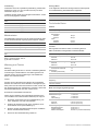 6
6
-
 7
7
-
 8
8
-
 9
9
-
 10
10
-
 11
11
-
 12
12
-
 13
13
-
 14
14
-
 15
15
-
 16
16
-
 17
17
-
 18
18
-
 19
19
-
 20
20
-
 21
21
-
 22
22
-
 23
23
-
 24
24
-
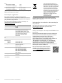 25
25
-
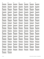 26
26


em outras línguas
- español: ACTIVSENSE DM3110R Guía de instalación
- français: ACTIVSENSE DM3110R Guide d'installation
- italiano: ACTIVSENSE DM3110R Guida d'installazione
- Deutsch: ACTIVSENSE DM3110R Installationsanleitung
- polski: ACTIVSENSE DM3110R Instrukcja instalacji
Artigos relacionados
Outros documentos
-
Castorama 928055 Instruções de operação
-
EDWARDS 2010-2-DACT Guia de instalação
-
Bosch Security Camera BasicDome Series Manual do usuário
-
Elvox 1300 Series Assembly Instructions Manual
-
-
Lutron Homeworks QS seeTouch HQWIS-NB-NONE Guia de instalação
-
Aurora AOne Pattress for AU-A1ZBKWC/AU-A1ZB2WDM Manual do proprietário
-
-
Vision TC2-CTL2 Manual do proprietário