Makita HP332D Manual do usuário
- Categoria
- Exercícios de força
- Tipo
- Manual do usuário

HP332D
EN
Cordless Hammer Driver Drill INSTRUCTION MANUAL 5
FR
Perceuse Percussion-
Visseuse sans Fil
MANUEL D’INSTRUCTIONS 11
DE
Akku- Schlagbohrschrauber BETRIEBSANLEITUNG 18
IT
Trapano avvitatore a
percussione a batteria
ISTRUZIONI PER L’USO 25
NL
Accuklopboor/-
schroefmachine
GEBRUIKSAANWIJZING 32
ES
Rotomartillo Atornillador
Inalámbrico
MANUAL DE
INSTRUCCIONES
39
PT
Parafusadeira/Furadeira de
Impacto a Bateria
MANUAL DE INSTRUÇÕES 46
DA
Akku skrue-/boremaskine
med slag
BRUGSANVISNING 53
EL
Κρουστικό
δραπανοκατσάβιδο
μπαταρίας
ΕΓΧΕΙΡΙΔΙΟ ΟΔΗΓΙΩΝ 59
TR
Akülü Darbeli Matkap
Tornavida
KULLANMA KILAVUZU 66

1
2
3
Fig.1
1
2
Fig.2
1
Fig.3
1
Fig.4
1
AB
Fig.5
1
Fig.6
1
2
3
4
Fig.7
1
2
3
4
Fig.8
2

1
3
2
Fig.9
1
2
3
Fig.10
1
2
Fig.11
Fig.12
1
Fig.13
Fig.14
1
2
Fig.15
Fig.16
3

Fig.17
4

5 ENGLISH
ENGLISH (Original instructions)
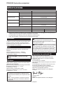
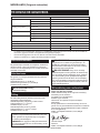
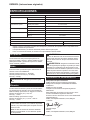
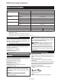
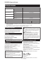
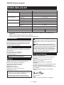
SPECIFICATIONS
Model: HP332D
Drilling capacities Concrete 8 mm
Steel 10 mm
Wood 28 mm
Fastening capacities Wood screw 5.1 mm x 63 mm
Machine screw M6
No load speed High (2) 0 - 1,500 min
-1
Low (1) 0 - 450 min
-1
Blows per minute High (2) 0 - 22,500 min
-1
Low (1) 0 - 6,750 min
-1
Overall length 168 mm
Rated voltage D.C. 10.8 V
Battery cartridge BL1015, BL1020B BL1040B
Net weight 1.1 kg 1.3 kg
• Duetoourcontinuingprogramofresearchanddevelopment,thespecicationshereinaresubjecttochange
without notice.
• Specicationsandbatterycartridgemaydifferfromcountrytocountry.
• Weight,withbatterycartridge,accordingtoEPTA-Procedure01/2003
Intended use
Thetoolisintendedforimpactdrillinginbrick,concrete
andstone.Itisalsosuitableforscrewdrivinganddrill-
ing without impact in wood, metal, ceramic and plastic.
Noise
ThetypicalA-weightednoiseleveldeterminedaccord-
ingtoEN60745:
Sound pressure level (L
pA
):82dB(A)
Sound power level (L
WA
):93dB(A)
Uncertainty(K):3dB(A)
WARNING: Wear ear protection.
Vibration
Thevibrationtotalvalue(tri-axialvectorsum)deter-
minedaccordingtoEN60745:
Workmode:impactdrillingintoconcrete
Vibrationemission(a
h,ID
):12.5m/s
2
Uncertainty(K):1.5m/s
2
Workmode:drillingintometal
Vibrationemission(a
h,D
):2.5m/s
2
or less
Uncertainty(K):1.5m/s
2
NOTE:Thedeclaredvibrationemissionvaluehas
beenmeasuredinaccordancewiththestandardtest
methodandmaybeusedforcomparingonetoolwith
another.
NOTE:Thedeclaredvibrationemissionvalue
mayalsobeusedinapreliminaryassessmentof
exposure.
WARNING:Thevibrationemissionduringactual
use of the power tool can differ from the declared
emission value depending on the ways in which the
tool is used.
WARNING: Be sure to identify safety measures
toprotecttheoperatorthatarebasedonanestima-
tion of exposure in the actual conditions of use (taking
account of all parts of the operating cycle such as
the times when the tool is switched off and when it is
running idle in addition to the trigger time).
EC Declaration of Conformity
For European countries only
MakitadeclaresthatthefollowingMachine(s):
DesignationofMachine:CordlessHammerDriverDrill
ModelNo./Type:HP332D
ConformstothefollowingEuropeanDirectives:
2006/42/EC
Theyaremanufacturedinaccordancewiththefollowing
standardorstandardizeddocuments:EN60745
Thetechnicalleinaccordancewith2006/42/ECis
availablefrom:
Makita, Jan-Baptist Vinkstraat 2, 3070, Belgium
11.6.2015
Yasushi Fukaya
Director
Makita, Jan-Baptist Vinkstraat 2, 3070, Belgium

6 ENGLISH
General power tool safety warnings
WARNING: Read all safety warnings and
all instructions. Failure to follow the warnings and
instructionsmayresultinelectricshock,reand/or
seriousinjury.
Save all warnings and instruc-
tions for future reference.
Theterm"powertool"inthewarningsreferstoyour
mains-operated(corded)powertoolorbattery-operated
(cordless) power tool.
Cordless hammer driver drill safety
warnings
1. Wear ear protectors when impact drilling.
Exposuretonoisecancausehearingloss.
2. Use auxiliary handle(s), if supplied with the
tool.Lossofcontrolcancausepersonalinjury.
3. Hold power tool by insulated gripping sur-
faces, when performing an operation where
the cutting accessory may contact hidden
wiring.Cuttingaccessorycontactinga"live"
wire may make exposed metal parts of the power
tool"live"andcouldgivetheoperatoranelectric
shock.
4. Hold power tool by insulated gripping sur-
faces, when performing an operation where
the fastener may contact hidden wiring.
Fastenerscontactinga"live"wiremaymake
exposedmetalpartsofthepowertool"live"and
could give the operator an electric shock.
5. Always be sure you have a rm footing. Be
sure no one is below when using the tool in
high locations.
6. Hold the tool rmly.
7. Keep hands away from rotating parts.
8. Do not leave the tool running. Operate the tool
only when hand-held.
9. Do not touch the bit or the workpiece immedi-
ately after operation; they may be extremely
hot and could burn your skin.
10. Some material contains chemicals which may
be toxic. Take caution to prevent dust inhala-
tion and skin contact. Follow material supplier
safety data.
SAVE THESE INSTRUCTIONS.
WARNING: DO NOT let comfort or familiarity
with product (gained from repeated use) replace
strict adherence to safety rules for the subject
product. MISUSE or failure to follow the safety
rules stated in this instruction manual may cause
serious personal injury.
Important safety instructions for
battery cartridge
1.
Before using battery cartridge, read all instructions
and cautionary markings on (1) battery charger, (2)
battery, and (3) product using battery.
2. Do not disassemble battery cartridge.
3. If operating time has become excessively
shorter, stop operating immediately. It may
result in a risk of overheating, possible burns
and even an explosion.
4. If electrolyte gets into your eyes, rinse them
out with clear water and seek medical atten-
tion right away. It may result in loss of your
eyesight.
5. Do not short the battery cartridge:
(1) Do not touch the terminals with any con-
ductive material.
(2) Avoid storing battery cartridge in a con-
tainer with other metal objects such as
nails, coins, etc.
(3) Do not expose battery cartridge to water
or rain.
A battery short can cause a large current
ow, overheating, possible burns and even a
breakdown.
6. Do not store the tool and battery cartridge in
locations where the temperature may reach or
exceed 50 °C (122 °F).
7. Do not incinerate the battery cartridge even if
it is severely damaged or is completely worn
out. The battery cartridge can explode in a re.
8. Be careful not to drop or strike battery.
9. Do not use a damaged battery.
10. Follow your local regulations relating to dis-
posal of battery.
SAVE THESE INSTRUCTIONS.
CAUTION: Only use genuine Makita batteries.
Useofnon-genuineMakitabatteries,orbatteriesthat
havebeenaltered,mayresultinthebatterybursting
causingres,personalinjuryanddamage.Itwill
also void the Makita warranty for the Makita tool and
charger.
Tips for maintaining maximum
battery life
1. Charge the battery cartridge before completely
discharged. Always stop tool operation and
charge the battery cartridge when you notice
less tool power.
2. Never recharge a fully charged battery car-
tridge. Overcharging shortens the battery
service life.
3. Charge the battery cartridge with room tem-
perature at 10 °C - 40 °C (50 °F - 104 °F). Let
a hot battery cartridge cool down before
charging it.

7 ENGLISH
FUNCTIONAL
DESCRIPTION
CAUTION: Always be sure that the tool is
switched off and the battery cartridge is removed
before adjusting or checking function on the tool.
Installing or removing battery
cartridge
CAUTION: Always switch off the tool before
installing or removing of the battery cartridge.
CAUTION: Hold the tool and the battery car-
tridge rmly when installing or removing battery
cartridge.Failuretoholdthetoolandthebattery
cartridgermlymaycausethemtoslipoffyourhands
andresultindamagetothetoolandbatterycartridge
andapersonalinjury.
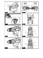
►Fig.1: 1. Red indicator 2. Button 3. Battery cartridge
Toremovethebatterycartridge,slideitfromthetool
whileslidingthebuttononthefrontofthecartridge.
Toinstallthebatterycartridge,alignthetongueonthe
batterycartridgewiththegrooveinthehousingandslip
it into place. Insert it all the way until it locks in place
with a little click. If you can see the red indicator on the
uppersideofthebutton,itisnotlockedcompletely.
CAUTION: Always install the battery cartridge
fully until the red indicator cannot be seen. If not,
itmayaccidentallyfalloutofthetool,causinginjuryto
you or someone around you.
CAUTION: Do not install the battery cartridge
forcibly. If the cartridge does not slide in easily, it is
notbeinginsertedcorrectly.
Battery protection system
Thetoolisequippedwithabatteryprotectionsystem.
Thissystemautomaticallycutsoffpowertothemotorto
extendbatterylife.
Thetoolwillautomaticallystopduringoperationifthe
tooland/orbatteryareplacedunderoneofthefollowing
conditions:
Overloaded:
Thetoolisoperatedinamannerthatcausesittodraw
anabnormallyhighcurrent.
In this situation, turn the tool off and stop the application
thatcausedthetooltobecomeoverloaded.Thenturn
the tool on to restart.
Ifthetooldoesnotstart,thebatteryisoverheated.In
thissituation,letthebatterycoolbeforeturningthetool
on again.
Low battery voltage:
Theremainingbatterycapacityistoolowandthetool
will not operate. If you turn the tool on, the motor runs
againbutstopssoon.Inthissituation,removeand
rechargethebattery.
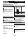
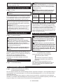
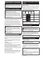
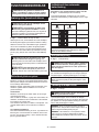
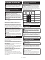
Indicating the remaining battery
capacity
Only for battery cartridges with "B" at the end of the
model number
►Fig.2: 1. Indicator lamps 2.Checkbutton
Pressthecheckbuttononthebatterycartridgetoindi-
catetheremainingbatterycapacity.Theindicatorlamps
light up for few seconds.
Indicator lamps Remaining
capacity
Lighted Off
75% to 100%
50% to 75%
25% to 50%
0% to 25%
NOTE: Depending on the conditions of use and the
ambienttemperature,theindicationmaydifferslightly
from the actual capacity.
Switch action
►Fig.3: 1. Switch trigger
CAUTION: Before inserting the battery car-
tridge into the tool, always check to see that the
switch trigger actuates properly and returns to
the "OFF" position when released.
Tostartthetool,simplypulltheswitchtrigger.Tool
speedisincreasedbyincreasingpressureontheswitch
trigger. Release the switch trigger to stop.
NOTE:Thetoolautomaticallystopsifyoukeeppull-
ingtheswitchtriggerforabout6minutes.
Lighting up the front lamp
►Fig.4: 1. Lamp
CAUTION: Do not look in the light or see the
source of light directly.
Pulltheswitchtriggertolightupthelamp.Thelamp
keepsonlightingwhiletheswitchtriggerisbeingpulled.
Thelampgoesoutapproximately10secondsafter
releasing the switch trigger.
NOTE: Use a dry cloth to wipe the dirt off the lens of
the lamp. Be careful not to scratch the lens of lamp, or
it may lower the illumination.
NOTE:Whenthetoolisoverheated,thelightashes
foroneminute,andthentheLEDdisplaygoesoff.In
thiscase,cooldownthetoolbeforeoperatingagain.

8 ENGLISH
Reversing switch action
►Fig.5: 1. Reversing switch lever
CAUTION: Always check the direction of
rotation before operation.
CAUTION: Use the reversing switch only after
the tool comes to a complete stop. Changing the
directionofrotationbeforethetoolstopsmaydam-
age the tool.
CAUTION: When not operating the tool,
always set the reversing switch lever to the neu-
tral position.
Thistoolhasareversingswitchtochangethedirection
of rotation. Depress the reversing switch lever from the
AsideforclockwiserotationorfromtheBsideforcoun-
terclockwise rotation.
When the reversing switch lever is in the neutral posi-
tion,theswitchtriggercannotbepulled.
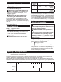
Speed change
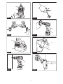
►Fig.6: 1. Speed change lever
CAUTION: Always set the speed change lever
fully to the correct position. If you operate the
tool with the speed change lever positioned halfway
betweenthe"1"sideand"2"side,thetoolmaybe
damaged.
CAUTION: Do not use the speed change lever
while the tool is running.Thetoolmaybedamaged.
Position of
speed
change lever
Speed Torque Applicable
operation
1 Low High Heavy load-
ing operation
2 High Low Light loading
operation
Tochangethespeed,switchoffthetoolrst.Select
the"2"sideforhighspeedor"1"forlowspeedbuthigh
torque.Besurethatthespeedchangeleverissettothe
correctpositionbeforeoperation.
If the tool speed is coming down extremely during the
operationwith"2",slidethelevertothe"1"andrestart
the operation.
Selecting the action mode
CAUTION: Always set the ring correctly to
your desired mode mark. If you operate the tool
with the ring positioned halfway between the
mode marks, the tool may be damaged.
CAUTION: When you change the position
from " " to other modes, it may be a little dif-
culty to slide the action mode changing ring. In
this case, switch on and run the tool for a second
at the " " position, then stop the tool and slide
the ring to your desired position.
►Fig.7: 1.Actionmodechangingring2.Adjusting
ring 3. Graduation 4.Arrow
Thistoolhasthreeactionmodes.
•
Drilling mode (rotation only)
•
Hammer drilling mode (rotation with
hammering)
•
Screwdriving mode (rotation with clutch)
Selectonemodesuitableforyourwork.Turnthe
action mode changing ring and align the mark that you
selectedwiththearrowonthetoolbody.
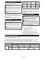
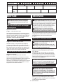
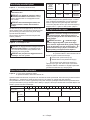
Adjusting the fastening torque
►Fig.8: 1.Actionmodechangingring2.Adjusting
ring 3. Graduation 4.Arrow
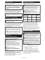
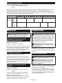
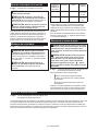
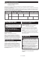
Thefasteningtorquecanbeadjustedin20stepsbyturningtheadjustingring.Alignthegraduationswiththearrow
onthetoolbody.Youcangettheminimumfasteningtorqueat1andmaximumtorqueat20.
Before actual operation, drive a trial screw into your material or a piece of duplicate material to determine which
torquelevelisrequiredforaparticularapplication.Thefollowingshowstheroughguideoftherelationshipbetween
the screw size and graduation.
Graduation 1 2 3 4 5 6 7 8 9 10 11 12 13 14 15 16 17 18 19 20
Machine screw M4 M5 M6
Wood
screw
Soft wood
(e.g. pine)
– ɸ3.5 x 22 ɸ4.1x 38 –
Hard wood
(e.g. lauan)
– ɸ3.5 x 22 ɸ4.1x 38 –

9 ENGLISH
ASSEMBLY
CAUTION: Always be sure that the tool is
switched off and the battery cartridge is removed
before carrying out any work on the tool.
Installing or removing driver bit/
drill bit
Optional accessory
►Fig.9: 1. Sleeve 2. Close 3. Open
Turnthesleevecounterclockwisetoopenthechuck
jaws.Placethedriverbit/drillbitinthechuckasfar
asitwillgo.Turnthesleeveclockwisetotightenthe
chuck.Toremovethedriverbit/drillbit,turnthesleeve
counterclockwise.
Installing hook
►Fig.10: 1. Groove 2. Hook 3. Screw
Thehookisconvenientfortemporarilyhangingthetool.
Thiscanbeinstalledoneithersideofthetool.Toinstall
the hook, insert it into a groove in the tool housing on
eithersideandthensecureitwithascrew.Toremove,
loosen the screw and then take it out.
Installing driver bit holder
Optional accessory
►Fig.11: 1.Driverbitholder2.Driverbit
Fitthedriverbitholderintotheprotrusionatthetoolfoot
on either right or left side and secure it with a screw.
Whennotusingthedriverbit,keepitinthedriverbit
holders.Driverbits45mm-longcanbekeptthere.
OPERATION
CAUTION: Always insert the battery cartridge
all the way until it locks in place. If you can see
theredpartontheuppersideofthebutton,itisnot
locked completely. Insert it fully until the red part can-
notbeseen.Ifnot,itmayaccidentallyfalloutofthe
tool,causinginjurytoyouorsomeonearoundyou.
CAUTION: When the speed comes down
extremely, reduce the load or stop the tool to
avoid the tool damage.
Holdthetoolrmlywithonehandonthegripandthe
otherhandonthebottomofthebatterycartridgeto
control the twisting action.
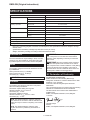
►Fig.12
Screwdriving operation
CAUTION: Adjust the adjusting ring to the
proper torque level for your work.
CAUTION: Make sure that the driver bit is
inserted straight in the screw head, or the screw
and/or driver bit may be damaged.
First, turn the action mode changing ring so that the
arrowonthetoolbodypointstothe marking.
Placethepointofthedriverbitinthescrewheadand
apply pressure to the tool. Start the tool slowly and then
increase the speed gradually. Release the switch trigger
as soon as the clutch cuts in.
NOTE: When driving wood screw, pre-drill a pilot hole
2/3thediameterofthescrew.Itmakesdrivingeasier
and prevents splitting of the workpiece.
Hammer drilling operation
CAUTION:
There is a tremendous and sudden
twisting force exerted on the tool/drill bit at the time of
hole breakthrough, when the hole becomes clogged
with chips and particles, or when striking reinforcing
rods embedded in the concrete.
First, turn the action mode changing ring so that the
arrowonthetoolbodypointstothe marking.The
adjustingringcanbealignedinanytorquelevelsfor
this operation.
Besuretouseatungsten-carbidetippeddrillbit.
Positionthedrillbitatthedesiredlocationforthehole,
then pull the switch trigger. Do not force the tool. Light
pressuregivesbestresults.Keepthetoolinposition
and prevent it from slipping away from the hole.
Donotapplymorepressurewhentheholebecomes
clogged with chips or particles. Instead, run the tool at
anidle,thenremovethedrillbitpartiallyfromthehole.
Byrepeatingthisseveraltimes,theholewillbecleaned
outandnormaldrillingmayberesumed.
Blow-out bulb
Optional accessory
►Fig.13: 1.Blow-outbulb
Afterdrillingthehole,usetheblow-outbulbtocleanthe
dust out of the hole.
Drilling operation
First,turntheadjustingringsothatthepointerpointsto
the marking.Thenproceedasfollows.
Drilling in wood
Whendrillinginwood,thebestresultsareobtained
withwooddrillsequippedwithaguidescrew.Theguide
screwmakesdrillingeasierbypullingthedrillbitinto
the workpiece.
Drilling in metal
Topreventthedrillbitfromslippingwhenstartinga
hole, make an indentation with a center-punch and
hammeratthepointtobedrilled.Placethepointofthe

10 ENGLISH
drillbitintheindentationandstartdrilling.
Useacuttinglubricantwhendrillingmetals.Theexcep-
tionsareironandbrasswhichshouldbedrilleddry.
CAUTION: Pressing excessively on the tool
will not speed up the drilling. In fact, this excessive
pressure will only serve to damage the tip of your drill
bit,decreasethetoolperformanceandshortenthe
service life of the tool.
CAUTION: Hold the tool rmly and exert care
when the drill bit begins to break through the
workpiece.Thereisatremendousforceexertedon
thetool/drillbitatthetimeofholebreakthrough.
CAUTION: A stuck drill bit can be removed
simply by setting the reversing switch to reverse
rotation in order to back out. However, the tool
may back out abruptly if you do not hold it rmly.
CAUTION: Always secure small workpieces
in a vise or similar hold-down device.
CAUTION: If the tool is operated continuously
until the battery cartridge has discharged, allow
the tool to rest for 15 minutes before proceeding
with a fresh battery.
Using the tool as a hand screwdriver
►Fig.14
Switch off the tool.
Move the reversing switch lever to the neutral position.
Turntheactionmodechangingringsothatthearrow
points to the
marking.
Turnthetool.
NOTE:Thisuseisconvenientforcheckingthe
screwdriving.
NOTE:Donotusethetoolforworkrequiringexces-
siveforce,suchastighteningboltorremovingrusted
screws.
Using holster
Optional accessory
CAUTION: When using the holster, remove a
driver bit/drill bit from the tool.
CAUTION: Turn off the tool and wait until it
comes to a complete stop before placing it in the
holster.
Be sure to close the holster securely with the
holster button so that it holds the tool rmly.
1. Threadawaistbeltorsimilarthroughholster
holder.
►Fig.15: 1. Holster holder 2.Waistbelt
2. Putthetoolintheholsterandlockitwiththehol-
sterbutton.
►Fig.16
►Fig.17
Youcankeeptwodriverbitsatthefrontoftheholster.
MAINTENANCE
CAUTION: Always be sure that the tool is
switched off and the battery cartridge is removed
before attempting to perform inspection or
maintenance.
NOTICE: Never use gasoline, benzine, thinner,
alcohol or the like. Discoloration, deformation or
cracks may result.
TomaintainproductSAFETYandRELIABILITY,
repairs,anyothermaintenanceoradjustmentshould
beperformedbyMakitaAuthorizedorFactoryService
Centers, always using Makita replacement parts.
OPTIONAL
ACCESSORIES
CAUTION: These accessories or attachments
are recommended for use with your Makita tool
specied in this manual.Theuseofanyother
accessories or attachments might present a risk of
injurytopersons.Onlyuseaccessoryorattachment
for its stated purpose.
If you need any assistance for more details regard-
ing these accessories, ask your local Makita Service
Center.
• Drillbits
• Driverbits
• Socketbits
• Tungsten-carbidetippeddrillbit
• Blow-outbulb
• Driverbitholder
• Hook
• Holster
• Makitagenuinebatteryandcharger
NOTE:Someitemsinthelistmaybeincludedinthe
toolpackageasstandardaccessories.Theymay
differ from country to country.

11 FRANÇAIS
FRANÇAIS (Instructions originales)
SPÉCIFICATIONS
Modèle : HP332D
Capacités de perçage Béton 8 mm
Acier 10 mm
Bois 28 mm
Capacités de serrage Visàbois 5,1 mm x 63 mm
Vismécanique M6
Vitesse à vide Élevée (2) 0 à 1 500 min
-1
Basse (1) 0 à 450 min
-1
Frappes par minute Élevée (2) 0 à 22 500 min
-1
Basse (1) 0 à 6 750 min
-1
Longueur totale 168 mm
Tensionnominale 10,8 V CC
Batterie BL1015, BL1020B BL1040B
Poidsnet 1,1 kg 1,3 kg
• Étantdonnél’évolutionconstantedenotreprogrammederechercheetdedéveloppement,lesspécications
contenuesdanscemanuelsontsujettesàmodicationsanspréavis.
• Lesspécicationsetlabatteriepeuventêtredifférentessuivantlespays.
• Poids,aveclabatterie,conformémentàlaprocédureEPTA-01/2003
Utilisations
L’outil est conçu pour le perçage avec percussion dans
labrique,lebétonetlapierre.Ilconvientaussipour
levissageetperçagesanspercussiondanslebois,le
métal,lacéramiqueetleplastique.
Bruit
NiveaudebruitpondéréAtypique,déterminéselon
EN60745:
Niveau de pression sonore (L
pA
):82dB(A)
Niveau de puissance sonore (L
WA
):93dB(A)
Incertitude(K):3dB(A)
AVERTISSEMENT : Portez un serre-tête
antibruit.
Vibrations
Valeurtotaledevibrations(sommedevecteurtriaxial)
déterminéeselonEN60745:
Modedetravail:perçageparpercussiondanslebéton
Émissiondevibrations(a
h, ID
):12,5m/s
2
Incertitude(K):1,5m/s
2
Modedetravail:perçagedanslemétal
Émissiondevibrations(a
h,D
):2,5m/s
2
ou moins
Incertitude(K):1,5m/s
2
NOTE :Lavaleurd’émissiondevibrationsdéclarée
a été mesurée conformément à la méthode de test
standardetpeutêtreutiliséepourcomparerlesoutils
entre eux.
NOTE :Lavaleurd’émissiondevibrationsdéclarée
peutaussiêtreutiliséepourl’évaluationpréliminaire
de l’exposition.
AVERTISSEMENT :L’émissiondevibrations
lorsdel’usageréeldel’outilélectriquepeutêtre
différente de la valeur d’émission déclarée, suivant la
façon dont l’outil est utilisé.
AVERTISSEMENT : Les mesures de sécurité à
prendrepourprotégerl’utilisateurdoiventêtrebasées
sur une estimation de l’exposition dans des condi-
tions réelles d’utilisation (en tenant compte de toutes
les composantes du cycle d’utilisation, comme par
exemplelemomentdesamisehorstension,lorsqu’il
tourne à vide et le moment de son déclenchement).
Déclaration de conformité CE
Pour les pays européens uniquement
Makitadéclarequelaoulesmachinessuivantes:
Désignationdelamachine:PerceusePercussion-
Visseuse sans Fil
N°demodèle/Type:HP332D
sontconformesauxDirectiveseuropéennessuivantes:
2006/42/CE
etsontfabriquéesconformémentauxnormesouaux
documentsnormaliséssuivants:EN60745
Ladocumentationtechniqueconformeàlanorme
2006/42/CEestdisponibleauprèsde:
Makita,Jan-BaptistVinkstraat2,3070,Belgique
11.6.2015
Yasushi Fukaya
Directeur
Makita,Jan-BaptistVinkstraat2,3070,Belgique

12 FRANÇAIS
Consignes de sécurité générales
pour outils électriques
AVERTISSEMENT : Lisez toutes les
consignes de sécurité et toutes les instructions. Il
yarisqued’électrocution,d’incendieet/oudegraves
blessuressilesmisesengardeetlesinstructionsne
sont pas respectées.
Conservez toutes les mises en
garde et instructions pour réfé-
rence ultérieure.
Leterme«outilélectrique»danslesavertissements
faitréférenceàl’outilélectriquealimentéparlesecteur
(aveccordond’alimentation)ouàl’outilélectriquefonc-
tionnantsurbatterie(sanscordond’alimentation).
Consignes de sécurité pour
perceuse percussion-visseuse
sans l
1. Portez des protections d’oreilles lorsque
vous effectuez un perçage avec percussion.
L’expositionaubruitpeutentraînerlasurdité.
2. Utilisez la ou les poignées auxiliaires, si l’outil
en possède.Toutepertedemaîtrisedel’outil
comporteunrisquedeblessure.
3.
Tenez l’outil électrique par des surfaces de prise
isolées lorsque vous effectuez une tâche au cours
de laquelle l’accessoire de coupe peut entrer en
contact avec des ls cachés. Le contact de l’acces-
soiredecoupeavecunlsoustensionpeuttransmettre
ducourantdanslespiècesmétalliquesexposéesde
l’outil et électrocuter l’opérateur.
4.
Tenez l’outil électrique par des surfaces de prise
isolées lorsque vous effectuez une tâche au cours
de laquelle la vis ou le boulon peut entrer en contact
avec des ls cachés.Lecontactdelavisouduboulon
avecunlsoustensionpeuttransmettreducourant
danslespiècesmétalliquesexposéesdel’outilet
électrocuter l’opérateur.
5.
Assurez-vous toujours de travailler en position stable.
Veillez à ce que personne ne se trouve en dessous de
vous quand vous utilisez l’outil en hauteur.
6. Tenez l’outil fermement.
7. Gardez les mains éloignées des pièces en
rotation.
8. Ne vous éloignez pas en laissant l’outil tour-
ner. Ne le faites fonctionner que lorsque vous
l’avez bien en main.
9. Ne touchez pas l’embout ou la pièce immé-
diatement après l’exécution du travail ; ils
peuvent être extrêmement chauds et vous
brûler la peau.
10. Certains matériaux contiennent des produits
chimiques qui peuvent être toxiques. Prenez
garde de ne pas avaler la poussière et évitez
tout contact avec la peau. Suivez les données
de sécurité du fournisseur du matériau.
CONSERVEZ CES
INSTRUCTIONS.
AVERTISSEMENT : NE vous laissez PAS
tromper (au l d’une utilisation répétée) par un
sentiment d’aisance et de familiarité avec le
produit, en négligeant le respect rigoureux des
consignes de sécurité qui accompagnent le pro-
duit en question. La MAUVAISE UTILISATION de
l’outil ou l’ignorance des consignes de sécurité
indiquées dans ce mode d’emploi peut entraîner
de graves blessures.
Consignes de sécurité importantes
pour la batterie
1. Avant d’utiliser la batterie, lisez toutes les
instructions et précautions relatives (1) au
chargeur de batterie, (2) à la batterie, et (3) au
produit utilisant la batterie.
2. Ne démontez pas la batterie.
3. Cessez immédiatement l’utilisation si le temps
de fonctionnement devient excessivement
court. Il y a risque de surchauffe, de brûlures,
voire d’explosion.
4. Si l’électrolyte pénètre dans vos yeux, rin-
cez-les à l’eau claire et consultez immédiate-
ment un médecin. Il y a risque de perte de la
vue.
5. Ne court-circuitez pas la batterie :
(1) Ne touchez les bornes avec aucun maté-
riau conducteur.
(2) Évitez de ranger la batterie dans un
conteneur avec d’autres objets métal-
liques, par exemple des clous, des pièces
de monnaie, etc.
(3) N’exposez pas la batterie à l’eau ou à la
pluie.
Un court-circuit de la batterie peut provoquer
une intensité de courant élevée, une sur-
chauffe, parfois des brûlures et même une
panne.
6. Ne rangez pas l’outil et la batterie dans un
endroit où la température risque d’atteindre ou
de dépasser 50 °C.
7. Ne jetez pas la batterie au feu même si elle est
sérieusement endommagée ou complètement
épuisée. La batterie peut exploser au contact
du feu.
8. Évitez de laisser tomber ou de cogner la
batterie.
9. N’utilisez pas la batterie si elle est
endommagée.
10. Suivez les réglementations locales en matière
de mise au rebut des batteries.
CONSERVEZ CES
INSTRUCTIONS.
ATTENTION : N’utilisez que des batteries
Makita d’origine.L’utilisationdebatteriesdemarque
autrequeMakitaoudebatteriesmodiéespeutpro-
voquerl’explosiondesbatteries,cequiprésenteun
risqued’incendie,dedommagesmatérielsetcorpo-
rels. Cela annulera également la garantie Makita pour
l’outil et le chargeur Makita.

13 FRANÇAIS
Conseils pour assurer la durée
de vie optimale de la batterie
1. Chargez la batterie avant qu’elle ne soit com-
plètement déchargée. Arrêtez toujours l’outil
et rechargez la batterie quand vous remarquez
que la puissance de l’outil diminue.
2. Ne rechargez jamais une batterie complète-
ment chargée. La surcharge réduit la durée de
service de la batterie.
3. Chargez la batterie à une température
ambiante comprise entre 10 °C et 40 °C. Avant
de charger une batterie chaude, laissez-la
refroidir.
DESCRIPTION DU
FONCTIONNEMENT
ATTENTION : Assurez-vous toujours que
l’outil est hors tension et que sa batterie est
retirée avant de l’ajuster ou de vérier son
fonctionnement.
Insertion ou retrait de la batterie
ATTENTION : Éteignez toujours l’outil avant
de mettre en place ou de retirer la batterie.
ATTENTION : Tenez fermement l’outil et la
batterie lors de la mise en place ou du retrait de
la batterie. Si vous ne tenez pas fermement l’outil
etlabatterie,ilspeuventvousglisserdesmains,et
s’abîmerouvousblesser.
►Fig.1: 1. Voyant rouge 2. Bouton 3. Batterie
Pourretirerlabatterie,faites-laglisserhorsdel’outil
toutenfaisantglisserleboutonàl’avantdelabatterie.
Pourmettreenplacelabatterie,alignezlalanguettesur
labatterieaveclarainuresurlecompartimentetinsé-
rez-la.Insérez-laàfondjusqu’àcequ’unlégerdéclic
se fasse entendre. Si le voyant rouge sur le dessus du
boutonestvisible,celasigniequ’ellen’estpasbien
verrouillée.
ATTENTION : Insérez toujours complètement
la batterie jusqu’à ce que le voyant rouge ne soit
plus visible.Sinon,ellepourraittomberacciden-
tellementdel’outil,aurisquedevousblesseroude
blesserquelqu’unsetrouvantprèsdevous.
ATTENTION : N’insérez pas la batterie de
force.Sielleneglissepasfacilement,c’estquevous
ne l’insérez pas correctement.
Système de protection de la batterie
L’outilestéquipéd’unsystèmedeprotectiondelabatterie.
Cesystèmecoupeautomatiquementlecourantdel’outilpour
prolongerladuréedeservicedelabatterie.
L’outils’arrêteraautomatiquementencoursd’utilisation
sil’outilet/oulabatteriesetrouvedansl’uneoul’autre
dessituationssuivantes:
Surcharge :
L’outilestutilisédemanièretellequ’ilconsommeun
courant anormalement élevé.
Danscecas,éteignezl’outiletarrêtezlatâcheayant
provoquélasurchargedel’outil.Puisrallumezl’outil
pourreprendrelatâche.
Sil’outilnedémarrepas,c’estquelabatterieasur-
chauffé.Danscecas,laissezlabatterierefroidiravant
de rallumer l’outil.
Faible tension de la batterie :
Lachargerestantedelabatterieesttropfaibleetl’outil
ne fonctionne pas. Si vous mettez l’outil sous tension,
lemoteurredémarre,maiss’arrêterapidement.Lecas
échéant,retirezetrechargezlabatterie.
Indication de la charge restante de
la batterie
Uniquement pour les batteries dont le numéro de
modèle se termine par « B »
►Fig.2: 1.Témoins2.Boutondevérication
Appuyezsurleboutondevéricationsurlabatterie
pourindiquerlachargerestantedelabatterie.Les
témoinss’allumentpendantquelquessecondes.
Témoins Charge
restante
Allumé Éteint
75 % à 100 %
50 % à 75 %
25 % à 50 %
0 % à 25 %
NOTE : Selon les conditions d’utilisation et la tem-
pératureambiante,l’indicationpeutêtrelégèrement
différente de la capacité réelle.
Fonctionnement de la gâchette
►Fig.3: 1.Gâchette
ATTENTION : Avant d’insérer la batterie dans
l’outil, vériez toujours que la gâchette fonc-
tionne bien et revient en position d’arrêt lorsque
vous la relâchez.
Ilsuftd’enclencherlagâchettepourdémarrerl’outil.
Lavitessedel’outilaugmenteàmesurequel’onaccroît
lapressionexercéesurlagâchette.Pourl’arrêter,
relâchezlagâchette.
NOTE :L’outils’arrêteraautomatiquementsivous
continuezd’enclencherlagâchettependant6
minutes environ.

14 FRANÇAIS
Allumage de la lampe avant
►Fig.4: 1. Lampe
ATTENTION : Évitez de regarder directement
le faisceau lumineux ou sa source.
Enclenchezlagâchettepourallumerlalampe.La
lamperestealluméetantquelagâchetteestenclen-
chée. La lampe s’éteint environ 10 secondes après
avoirrelâchélagâchette.
NOTE :
Retirez la saleté sur la lentille de la lampe avec un
chiffonsec.Prenezsoindenepaséraerlalentilledela
lampe sous peine de diminuer son éclairage.
NOTE
:Encasdesurchauffedel’outil,lalumièreclignote
pendantuneminute,puisl’afcheuràDELs’éteint.Ilfaut
alors laisser refroidir l’outil avant de le remettre en marche.
Fonctionnement de l’inverseur
►Fig.5: 1. Levier de l’inverseur
ATTENTION : Vériez toujours le sens de
rotation avant d’utiliser l’outil.
ATTENTION : N’utilisez l’inverseur qu’une
fois que l’outil est complètement arrêté. Si vous
changezlesensderotationavantl’arrêtdel’outil,
vousrisquezdel’endommager.
ATTENTION : Lorsque vous n’utilisez pas
l’outil, placez toujours le levier de l’inverseur en
position neutre.
L’outilpossèdeuninverseurquipermetdechanger
lesensderotation.Enfoncezlelevierdel’inverseur
ducôtéApourunerotationdanslesensdesaiguilles
d’une montre, ou du côté B pour une rotation dans le
sens inverse des aiguilles d’une montre.
Lagâchettenepeutpasêtreenclenchéelorsquele
levier de l’inverseur se trouve en position neutre.
Changement de vitesse
►Fig.6: 1. Levier de changement de vitesse
ATTENTION : Mettez toujours le levier de
changement de vitesse parfaitement sur la bonne
position.Enutilisantl’outilaveclelevierdechange-
mentdevitesseplacéentrelescôtés«1»et«2»,
vousrisqueriezd’abîmerl’outil.
ATTENTION : Ne déplacez pas le levier de
changement de vitesse pendant que l’outil tourne.
Vousrisqueriezd’abîmerl’outil.
Position du
levier
de chan-
gement de
vitesse
Vitesse Couple Tâche
applicable
1 Faible Élevé Tâchedifcile
2 Élevée Faible Tâchefacile
Pourchangerdevitesse,mettezd’abordl’outilhors
tension.Sélectionnezlecôté«2»pourunevitesse
élevéeoulecôté«1»pourunevitesselenteavec
coupleélevé.Avantd’utiliserl’outil,assurez-vousquele
levierdechangementdevitessesetrouvesurlabonne
position.
Silavitessedel’outildiminueconsidérablementpen-
dantlatâcheavecleréglage«2»,faitesglisserle
leviersur«1»etrecommencez.
Sélection du mode de
fonctionnement
ATTENTION : Mettez toujours la bague par-
faitement sur le symbole du mode désiré. Vous
risquez d’abîmer l’outil si vous l’utilisez alors que
la bague se trouve entre deux symboles de mode.
ATTENTION : Lorsque vous changez la posi-
tion de « » à un autre mode, il peut s’avérer
un peu difcile de faire glisser la bague de chan-
gement de mode. Le cas échéant, mettez l’outil
sous tension et faites-le tourner pendant une
seconde en position « », puis arrêtez l’outil et
faites glisser la bague sur la position désirée.
►Fig.7: 1. Bague de changement de mode 2. Bague
de réglage 3. Graduation 4. Flèche
Cet outil offre trois modes de fonctionnement.
•
Modedeperçage(rotationuniquement)
•
Mode de perçage avec percussion (rotation
avec percussion)
•
Mode de vissage (rotation avec engrenage)
Sélectionnezlemodeconvenantàvotretâche.Tournez
labaguedechangementdemodeetalignezlerepère
quevousavezsélectionnésurlaèchedel’outil.
Réglage du couple de serrage
►Fig.8: 1. Bague de changement de mode 2. Bague
de réglage 3. Graduation 4. Flèche
Lecoupledeserragepeutêtreréglésurundes20niveauxentournantlabaguederéglage.Alignezlesgraduations
surlaèchedel’outil.Vouspouvezobteniruncoupledeserrageminimumensélectionnant1etuncouplemaximum
en sélectionnant 20.
Avantd’effectuerlevéritabletravail,faitesunessaidevissagedanslematériauenquestionoudansunmatériau
identiquepoursavoirquelestleniveaudecoupledeserragerequispourcetravailparticulier.Voustrouverezci-des-
sous une indication approximative de la relation entre la taille de vis et la graduation.

15 FRANÇAIS
Graduation 1 2 3 4 5 6 7 8 9 10 11 12 13 14 15 16 17 18 19 20
Vismécanique M4 M5 M6
Visàbois Bois mou
(comme le
pin)
– ɸ3,5 x 22 ɸ4,1 x 38 –
Bois franc
(comme le
méranti)
– ɸ3,5 x 22 ɸ4,1 x 38 –
ASSEMBLAGE
ATTENTION : Assurez-vous toujours que
l’outil est hors tension et que sa batterie est reti-
rée avant d’effectuer toute tâche dessus.
Installation ou retrait de l’embout de
vissage/foret
Accessoire en option
►Fig.9: 1. Manchon 2. Fermer 3. Ouvrir
Tournezlemanchondanslesenscontrairedesaiguilles
d’unemontrepourouvrirlesmâchoiresdumandrin.
Insérezl’emboutdevissage/foretàfonddansleman-
drin.Tournezlemanchondanslesensdesaiguilles
d’unemontrepourserrerlemandrin.Pourretirerl’em-
boutdevissage/foret,tournezlemanchondanslesens
contraire des aiguilles d’une montre.
Installation du crochet
►Fig.10: 1. Rainure 2. Crochet 3. Vis
L’outilestéquipéd’uncrochetpratiquequipermet
de l’accrocher temporairement. Ce crochet s’installe
d’uncôtécommedel’autredel’outil.Pourinstallerle
crochet, insérez-le dans une des rainures situées de
chaquecôtéducarterdel’outil,puisserrez-leavecune
vis.Pourl’enlever,desserrezlavisetretirez-le.
Installation du support d’embout de
vissage
Accessoire en option
►Fig.11: 1.Supportd’emboutdevissage2.Embout
de vissage
Mettezlesupportd’emboutdevissagedanslapartie
saillante du pied de l’outil, d’un côté ou de l’autre, et
xez-leàl’aided’unevis.
Lorsquevousn’utilisezpasl’emboutdevissage,ran-
gez-ledansundessupportsd’emboutdevissage.Ils
peuventcontenirdesemboutsdevissaged’unelon-
gueur de 45 mm.
UTILISATION
ATTENTION : Insérez toujours la batterie à
fond jusqu’à ce qu’elle se verrouille en place. Si
vous pouvez voir la partie rouge du côté supérieur du
bouton,labatterien’estpascomplètementverrouil-
lée.Insérez-lacomplètement,jusqu’àcequelapartie
rougenesoitplusvisible.Sinon,ellepourraittomber
accidentellementdel’outil,aurisquedevousblesser
oudeblesserquelqu’unsetrouvantprèsdevous.
ATTENTION : Lorsque la vitesse diminue
considérablement, réduisez la charge ou arrêtez
l’outil pour éviter de l’abîmer.
Tenezl’outilfermementenlesaisissantd’unemainpar
lapoignéeetdel’autreparledessousdelabatterie,
anderésisteràlaforcedetorsion.
►Fig.12
Vissage
ATTENTION : Mettez la bague de réglage sur
un niveau de couple de serrage adapté au travail
à effectuer.
ATTENTION : Assurez-vous que l’embout de
vissage est inséré bien droit dans la tête de vis,
sinon vous risquerez d’abîmer la vis et/ou l’em-
bout de vissage.
Tournezd’abordlabaguedechangementdemode,de
sortequelaèchesurl’outilpointesurlesymbole .
Placezlapointedel’emboutdevissagedanslatêtedeviset
appliquezunepressionsurl’outil.Faitesdémarrerl’outillente-
ment,puisaugmentezlavitessegraduellement.Relâchezla
gâchettedèsquel’engrenages’active.
NOTE :Lorsquevousinsérezunevisàbois,percez
d’abordunavant-troud’undiamètredu2/3decelui
delavis.Celafaciliteralevissageetéviteraquela
pièce ne se fende.
Perçage avec percussion
ATTENTION : Une très grande force de tor-
sion s’exerce soudainement sur l’outil/foret lors-
qu’il émerge sur la face opposée, lorsque le trou
est bouché par des copeaux ou particules ou lors
du contact avec des armatures dans le béton.
Tournezd’abordlabaguedechangementdemode,de
sortequelaèchesurl’outilpointesurlesymbole .
Labaguederéglagepeutêtrealignéesurn’importe
quelniveaudecoupledeserragepourcetteopération.

16 FRANÇAIS
Vousdevezutiliserunforetàpointedecarburede
tungstène.
Placezleforetàl’emplacementdésirépourpercerle
trou,puisenclenchezlagâchette.Neforcezpasl’outil.
Vousobtiendrezdemeilleursrésultatsavecunelégère
pression.Gardezl’outilenpositionetempêchez-lede
glisser hors du trou.
N’appliquezpasplusdepressionlorsqueletrouest
bouchépardescopeauxouparticules.Laissezplutôt
l’outil tourner au ralenti et retirez partiellement le foret
dutrou.Enrépétantcetteopérationplusieursfois,le
trousedéboucheraetvouspourrezreprendreleper-
çage normalement.
Poire soufante
Accessoire en option
►Fig.13: 1.Poiresoufante
Unefoisletroupercé,utilisezlapoiresoufantepour
en retirer les poussières.
Perçage
Tournezd’abordlabaguederéglagedesorteque
l’index pointe vers l’indication .Procédezensuite
comme suit.
Perçage dans le bois
Lorsquevouspercezdanslebois,vousobtiendrezun
résultatoptimalavecunforetàboiséquipéd’unevisde
guidage.Lavisdeguidagefaciliteleperçageenentraî-
nant le foret dans la pièce.
Perçage dans le métal
Pourqueleforetneglissepasquandvouscommencezà
percer le trou, faites une entaille à l’aide d’un pointeau et d’un
marteauàl’emplacementprévupourletrou.Placezlapointe
du foret dans l’entaille et commencez à percer.
Utilisezunlubriantdecoupepourpercerlesmétaux.
Seulsleferetlelaitondoiventêtrepercésàsec.
ATTENTION : Une pression excessive sur
l’outil n’accélèrera pas le perçage.Enfait,lapres-
sionexcessiveabîmeralapointeduforet,provoquera
unebaissederendementdel’outiletréduirasadurée
de service.
ATTENTION : Tenez l’outil fermement et
redoublez d’attention lorsque le foret commence
à sortir par la face opposée de la pièce. Une très
grandeforces’exercesurl’outil/foretlorsquecelui-ci
émerge sur la face opposée.
ATTENTION : Un foret coincé peut être retiré
en réglant simplement l’inverseur sur la rotation
inverse pour faire marche arrière. L’outil peut tou-
tefois faire brusquement marche arrière si vous
ne le tenez pas fermement.
ATTENTION : Immobilisez toujours les
petites pièces à travailler dans un étau ou un
dispositif de retenue similaire.
ATTENTION : Si l’outil est utilisé de manière
continue jusqu’à ce que la batterie se décharge,
laissez-le reposer 15 minutes avant de poursuivre
le travail avec une batterie fraîchement chargée.
Utilisation de l’outil comme un
tournevis à main
►Fig.14
Mettez l’outil hors tension.
Déplacez le levier de l’inverseur sur la position neutre.
Tournezlabaguedechangementdemode,desorte
quelaèchepointesurlesymbole
.
Tournezl’outil.
NOTE :Cetteutilisationpeutserévélerpratiquepour
vérierlevissage.
NOTE :N’utilisezpasl’outilpourdestâchesnécessi-
tantuneforceexcessive,commeleserragedebou-
lons ou le retrait de vis rouillées.
Utilisation de l’étui de type holster
Accessoire en option
ATTENTION : Lorsque vous utilisez l’étui de
type holster, retirez l’embout de vissage/foret de
l’outil.
ATTENTION : Mettez l’outil hors tension et
attendez qu’il s’arrête complètement avant de le
placer dans l’étui de type holster.
Veillez à fermer soigneusement l’étui de type
holster avec le bouton de l’étui pour qu’il retienne
fermement l’outil.
1. Passezuneceintureouunobjetsemblableparle
passant de l’étui de type holster.
►Fig.15: 1.Passantdel’étuidetypeholster
2. Ceinture
2. Placezl’outildansl’étuidetypeholsteretfer-
mez-leavecleboutondel’étui.
►Fig.16
►Fig.17
Vouspouvezgarderdeuxemboutsdevissagesur
l’avant de l’étui de type holster.
ENTRETIEN
ATTENTION : Assurez-vous toujours que
l’outil est hors tension et que la batterie est reti-
rée avant d’y effectuer tout travail d’inspection ou
d’entretien.
REMARQUE : N’utilisez jamais d’essence, ben-
zine, diluant, alcool ou autre produit similaire.
Cela risquerait de provoquer la décoloration, la
déformation ou la ssuration de l’outil.
PourassurerlaSÉCURITÉetlaFIABILITÉduproduit,
toute réparation, tout travail d’entretien ou de réglage
doiventêtreeffectuésparuncentred’entretienMakita
agréé, avec des pièces de rechange Makita.

17 FRANÇAIS
ACCESSOIRES EN
OPTION
ATTENTION : Ces accessoires ou pièces
complémentaires sont recommandés pour l’utili-
sation avec l’outil Makita spécié dans ce mode
d’emploi. L’utilisation de tout autre accessoire ou
piècecomplémentairepeutcomporterunrisquede
blessure.N’utilisezlesaccessoiresoupiècescomplé-
mentairesqu’auxnsauxquellesilsontétéconçus.
Pourobtenirplusdedétailssurcesaccessoires,
contactez votre centre d’entretien local Makita.
• Forets
• Emboutsdevissage
• Emboutsàdouille
• Foretàpointedecarburedetungstène
• Poiresoufante
• Supportd’emboutdevissage
• Crochet
• Étui de type holster
• Batterie et chargeur Makita d’origine
NOTE :Ilsepeutquecertainsélémentsdelaliste
soientcomprisdansl’emballagedel’outilentant
qu’accessoiresstandard.Ilspeuventvarierd’unpays
à l’autre.

18 DEUTSCH
DEUTSCH (Original-Anleitung)
TECHNISCHE DATEN
Modell: HP332D
Bohrkapazitäten Beton 8 mm
Stahl 10 mm
Holz 28 mm
Anzugskapazitäten Holzschraube 5,1 mm x 63 mm
Maschinenschraube M6
Leerlaufdrehzahl Hoch (2) 0 - 1.500 min
-1
Niedrig (1) 0 - 450 min
-1
Schlagzahl pro Minute Hoch (2) 0 - 22.500 min
-1
Niedrig (1) 0 - 6.750 min
-1
Gesamtlänge 168 mm
Nennspannung 10,8 V Gleichstrom
Akku BL1015, BL1020B BL1040B
Nettogewicht 1,1 kg 1,3 kg
• Wirbehaltenunsvor,ÄnderungendertechnischenDatenimZugederEntwicklungunddestechnischen
FortschrittsohnevorherigeAnkündigungvorzunehmen.
• DietechnischenDatenundderAkkukönnenvonLandzuLandunterschiedlichsein.
• GewichtmitAkkunachEPTA-Verfahren01/2003
Vorgesehene Verwendung
DasWerkzeugistfürSchlagbohreninZiegeln,
BetonundSteinvorgesehen.Eseignetsichauchfür
SchraubbetriebundnormalesBohreninHolz,Metall,
Keramik und Kunststoff.
Geräusch
TypischerA-bewerteterGeräuschpegelermitteltgemäß
EN60745:
Schalldruckpegel (L
pA
):82dB(A)
Schallleistungspegel (L
WA
):93dB(A)
Messunsicherheit(K):3dB(A)
WARNUNG: Einen Gehörschutz tragen.
Schwingungen
Schwingungsgesamtwert(Drei-Achsen-Vektorsumme)
ermitteltgemäßEN60745:
Arbeitsmodus:SchlagbohreninBeton
Schwingungsemission (a
h, ID
):12,5m/s
2
Messunsicherheit(K):1,5m/s
2
Arbeitsmodus:BohreninMetall
Schwingungsemission (a
h,D
):2,5m/s
2
oder weniger
Messunsicherheit(K):1,5m/s
2
HINWEIS:Derangegebene
Schwingungsemissionswert
wurdeimEinklangmitderStandardprüfmethodegemessen
undkannfürdenVergleichzwischenWerkzeugenherange-
zogen werden.
HINWEIS:Derangegebene
Schwingungsemissionswertkannauchfüreine
VorbewertungdesGefährdungsgradsverwendet
werden.
WARNUNG: Die Schwingungsemission während
dertatsächlichenBenutzungdesElektrowerkzeugs
kannjenachderBenutzungsweisedesWerkzeugs
vomangegebenenEmissionswertabweichen.
WARNUNG:IdentizierenSie
SicherheitsmaßnahmenzumSchutzdesBenutzers
anhand einer Schätzung des Gefährdungsgrads unter
dentatsächlichenBenutzungsbedingungen(unter
BerücksichtigungallerPhasendesArbeitszyklus,wie
z.B.Ausschalt-undLeerlaufzeitendesWerkzeugs
zusätzlichzurBetriebszeit).
EG-Konformitätserklärung
Nur für europäische Länder
Makitaerklärt,dassdiefolgende(n)Maschine(n):
BezeichnungderMaschine:
Akku-Schlagbohrschrauber
Modell-Nr./Typ:HP332D
EntsprichtdenfolgendeneuropäischenRichtlinien:
2006/42/EG
SiewerdengemäßdenfolgendenStandardsoderstan-
dardisiertenDokumentenhergestellt:EN60745
DietechnischeAkteinÜbereinstimmungmit2006/42/
EGisterhältlichvon:
Makita, Jan-Baptist Vinkstraat 2, 3070, Belgien
11.6.2015
Yasushi Fukaya
Direktor
Makita, Jan-Baptist Vinkstraat 2, 3070, Belgien

19 DEUTSCH
Allgemeine Sicherheitswarnungen
für Elektrowerkzeuge
WARNUNG: Lesen Sie alle
Sicherheitswarnungen und Anweisungen durch.
EineMissachtungderuntenaufgeführtenWarnungen
undAnweisungenkannzueinemelektrischen
Schlag,Brandund/oderschwerenVerletzungen
führen.
Bewahren Sie alle Warnungen
und Anweisungen für spätere
Bezugnahme auf.
DerAusdruck„Elektrowerkzeug“indenWarnhinweisen
beziehtsichaufIhrmitNetzstrom(mitKabel)oderAkku
(ohneKabel)betriebenesElektrowerkzeug.
Sicherheitswarnungen für
Akku- Schlagbohrschrauber
1. Tragen Sie Gehörschützer beim Schlagbohren.
LärmeinwirkungkannGehörschädigung
verursachen.
2. Benutzen Sie (einen) Zusatzgriff(e), sofern er
(sie) mit dem Werkzeug geliefert wurde(n).
VerlustderKontrollekannPersonenschäden
verursachen.
3. Halten Sie das Elektrowerkzeug an den iso-
lierten Griffächen, wenn Sie Arbeiten aus-
führen, bei denen die Gefahr besteht, dass
das Schneidwerkzeug verborgene Kabel
kontaktiert.BeiKontaktmiteinemStromführen-
denKabelkönnendiefreiliegendenMetallteile
desElektrowerkzeugsebenfallsStromführend
werden, so dass der Benutzer einen elektrischen
Schlag erleiden kann.
4. Halten Sie das Elektrowerkzeug an den iso-
lierten Griffächen, wenn Sie Arbeiten aus-
führen, bei denen die Gefahr besteht, dass
das Befestigungselement verborgene Kabel
kontaktiert.BeiKontaktmiteinemStromführen-
denKabelkönnendiefreiliegendenMetallteile
desElektrowerkzeugsebenfallsStromführend
werden, so dass der Benutzer einen elektrischen
Schlag erleiden kann.
5. Achten Sie stets auf sicheren Stand.
Vergewissern Sie sich bei Einsatz des
Werkzeugs an hochgelegenen Arbeitsplätzen,
dass sich keine Personen darunter aufhalten.
6. Halten Sie das Werkzeug mit festem Griff.
7. Halten Sie Ihre Hände von rotierenden Teilen
fern.
8. Lassen Sie das Werkzeug nicht unbeaufsich-
tigt laufen. Benutzen Sie das Werkzeug nur mit
Handhaltung.
9. Vermeiden Sie eine Berührung des Einsatzes
oder des Werkstücks unmittelbar nach der
Bearbeitung, weil die Teile noch sehr heiß sind
und Hautverbrennungen verursachen können.
10. Manche Materialien können giftige
Chemikalien enthalten. Treffen Sie
Vorsichtsmaßnahmen, um das Einatmen von
Arbeitsstaub und Hautkontakt zu verhüten.
Befolgen Sie die Sicherheitsdaten des
Materiallieferanten.
DIESE ANWEISUNGEN
AUFBEWAHREN.
WARNUNG: Lassen Sie sich NICHT durch
Bequemlichkeit oder Vertrautheit mit dem Produkt
(durch wiederholten Gebrauch erworben) von
der strikten Einhaltung der Sicherheitsregeln für
das vorliegende Produkt abhalten. MISSBRAUCH
oder Missachtung der Sicherheitsvorschriften in
dieser Anleitung können schwere Verletzungen
verursachen.
Wichtige Sicherheitsanweisungen
für Akku
1. Lesen Sie vor der Benutzung des Akkus alle
Anweisungen und Warnhinweise, die an (1)
Ladegerät, (2) Akku und (3) Akkuwerkzeug
angebracht sind.
2. Unterlassen Sie ein Zerlegen des Akkus.
3. Falls die Betriebszeit beträchtlich kürzer
geworden ist, stellen Sie den Betrieb sofort
ein. Anderenfalls besteht die Gefahr von
Überhitzung, möglichen Verbrennungen und
sogar einer Explosion.
4. Falls Elektrolyt in Ihre Augen gelangt, waschen
Sie sie mit sauberem Wasser aus, und
begeben Sie sich unverzüglich in ärztliche
Behandlung. Anderenfalls können Sie Ihre
Sehkraft verlieren.
5. Der Akku darf nicht kurzgeschlossen werden:
(1) Die Kontakte dürfen nicht mit leitfähigem
Material berührt werden.
(2) Lagern Sie den Akku nicht in einem
Behälter zusammen mit anderen
Metallgegenständen, wie z. B. Nägel,
Münzen usw.
(3) Setzen Sie den Akku weder Wasser noch
Regen aus.
Ein Kurzschluss des Akkus verursacht star-
ken Stromuss, der Überhitzung, mögliche
Verbrennungen und einen Defekt zur Folge
haben kann.
6. Lagern Sie das Werkzeug und den Akku nicht
an Orten, an denen die Temperatur 50 °C errei-
chen oder überschreiten kann.
7. Versuchen Sie niemals, den Akku zu verbren-
nen, selbst wenn er stark beschädigt oder
vollkommen verbraucht ist. Der Akku kann im
Feuer explodieren.
8. Achten Sie darauf, dass der Akku nicht fallen
gelassen oder Stößen ausgesetzt wird.
9. Benutzen Sie keine beschädigten Akkus.
10. Befolgen Sie die örtlichen Bestimmungen
bezüglich der Entsorgung von Akkus.
DIESE ANWEISUNGEN
AUFBEWAHREN.

20 DEUTSCH
VORSICHT: Verwenden Sie nur Original-
Makita-Akkus. Die Verwendung von Nicht-Original-
Makita-AkkusodervonAkkus,dieabgeändert
wordensind,kannzumBerstendesAkkusund
darausresultierendenBränden,Personenschäden
undBeschädigungführen.Außerdemwirddadurch
dieMakita-GarantiefürdasMakita-Werkzeugund
-Ladegerätungültig.
Hinweise zur Aufrechterhaltung
der maximalen
Akku-Nutzungsdauer
1. Laden Sie den Akku, bevor er vollkommen
erschöpft ist. Schalten Sie das Werkzeug stets
aus, und laden Sie den Akku, wenn Sie ein
Nachlassen der Werkzeugleistung feststellen.
2. Unterlassen Sie erneutes Laden eines voll
aufgeladenen Akkus. Überladen führt zu einer
Verkürzung der Nutzungsdauer des Akkus.
3. Laden Sie den Akku bei Raumtemperatur
zwischen 10 – 40 °C. Lassen Sie einen heißen
Akku abkühlen, bevor Sie ihn laden.
FUNKTIONSBESCHREIBUNG
VORSICHT: Vergewissern Sie sich vor
der Durchführung von Einstellungen oder
Funktionsprüfungen des Werkzeugs stets, dass
das Werkzeug ausgeschaltet und der Akku abge-
nommen ist.
Anbringen und Abnehmen des
Akkus
VORSICHT: Schalten Sie das Werkzeug
stets aus, bevor Sie den Akku anbringen oder
abnehmen.
VORSICHT: Halten Sie das Werkzeug und
den Akku beim Anbringen oder Abnehmen
des Akkus sicher fest. Wenn Sie das Werkzeug
unddenAkkunichtsicherfesthalten,können
sie Ihnen aus der Hand rutschen, was zu einer
BeschädigungdesWerkzeugsunddesAkkusundzu
Körperverletzungenführenkann.
►Abb.1: 1.RoteAnzeige2. Knopf 3.Akku
ZiehenSiedenAkkuzumAbnehmenvomWerkzeug
ab,währendSiedenKnopfanderVorderseitedes
Akkusverschieben.
RichtenSiezumAnbringendesAkkusdessen
FührungsfederaufdieNutimGehäuseaus,undschie-
benSiedenAkkuhinein.SchiebenSieihnvollständig
ein,bisermiteinemhörbarenKlickeneinrastet.Falls
dieroteAnzeigeanderOberseitedesKnopfessichtbar
ist,istderAkkunichtvollständigverriegelt.
VORSICHT: Schieben Sie den Akku stets bis
zum Anschlag ein, bis die rote Anzeige nicht mehr
sichtbar ist.AnderenfallskannerausdemWerkzeug
herausfallenundSieoderumstehendePersonen
verletzen.
VORSICHT: Unterlassen Sie
Gewaltanwendung beim Anbringen des Akkus.
FallsderAkkunichtreibungsloshineingleitet,ister
nicht richtig ausgerichtet.
Akku-Schutzsystem
DasWerkzeugistmiteinemAkku-Schutzsystemaus-
gestattet. Dieses System schaltet die Stromversorgung
desMotorsautomatischab,umdieAkku-Lebensdauer
zu verlängern.
DasWerkzeugschaltetsichwährenddesBetriebs
automatischab,wennWerkzeugund/oderAkkueiner
derfolgendenBedingungenunterliegen:
Überlastung:
DasWerkzeugwirdaufeineWeisebenutzt,dieeine
ungewöhnlichhoheStromaufnahmebewirkt.
Schalten Sie in dieser Situation das Werkzeug aus,
undbrechenSiedieArbeitab,dieeineÜberlastung
des Werkzeugs verursacht hat. Schalten Sie dann das
Werkzeug wieder ein, um neu zu starten.
FallsdasWerkzeugnichtstartet,istderAkkuüberhitzt.
LassenSiedenAkkuindieserSituationabkühlen,
bevorSiedasWerkzeugwiedereinschalten.
Niedrige Akkuspannung:
DieAkku-Restkapazitätistzuniedrig,unddas
Werkzeug funktioniert nicht. Wenn Sie das Werkzeug
einschalten,läuftderMotorwiederan,bleibtaberbald
daraufstehen.NehmenSieindieserSituationdenAkku
ab,undladenSieihnauf.
Anzeigen der Akku-Restkapazität
Nur für Akkus mit „B“ am Ende der Modellnummer
►Abb.2: 1.Anzeigelampen2.Prüftaste
DrückenSiediePrüftasteamAkku,umdieAkku-
Restkapazitätanzuzeigen.DieAnzeigelampenleuchten
wenige Sekunden lang auf.
Anzeigelampen Restkapazität
Erleuchtet Aus
75%bis100%
50%bis75%
25%bis50%
0%bis25%
HINWEIS:Abhängigvonden
Benutzungsbedingungenundder
UmgebungstemperaturkanndieAnzeigegeringfügig
vondertatsächlichenKapazitätabweichen.
A página está carregando...
A página está carregando...
A página está carregando...
A página está carregando...
A página está carregando...
A página está carregando...
A página está carregando...
A página está carregando...
A página está carregando...
A página está carregando...
A página está carregando...
A página está carregando...
A página está carregando...
A página está carregando...
A página está carregando...
A página está carregando...
A página está carregando...
A página está carregando...
A página está carregando...
A página está carregando...
A página está carregando...
A página está carregando...
A página está carregando...
A página está carregando...
A página está carregando...
A página está carregando...
A página está carregando...
A página está carregando...
A página está carregando...
A página está carregando...
A página está carregando...
A página está carregando...
A página está carregando...
A página está carregando...
A página está carregando...
A página está carregando...
A página está carregando...
A página está carregando...
A página está carregando...
A página está carregando...
A página está carregando...
A página está carregando...
A página está carregando...
A página está carregando...
A página está carregando...
A página está carregando...
A página está carregando...
A página está carregando...
A página está carregando...
A página está carregando...
A página está carregando...
A página está carregando...
-
 1
1
-
 2
2
-
 3
3
-
 4
4
-
 5
5
-
 6
6
-
 7
7
-
 8
8
-
 9
9
-
 10
10
-
 11
11
-
 12
12
-
 13
13
-
 14
14
-
 15
15
-
 16
16
-
 17
17
-
 18
18
-
 19
19
-
 20
20
-
 21
21
-
 22
22
-
 23
23
-
 24
24
-
 25
25
-
 26
26
-
 27
27
-
 28
28
-
 29
29
-
 30
30
-
 31
31
-
 32
32
-
 33
33
-
 34
34
-
 35
35
-
 36
36
-
 37
37
-
 38
38
-
 39
39
-
 40
40
-
 41
41
-
 42
42
-
 43
43
-
 44
44
-
 45
45
-
 46
46
-
 47
47
-
 48
48
-
 49
49
-
 50
50
-
 51
51
-
 52
52
-
 53
53
-
 54
54
-
 55
55
-
 56
56
-
 57
57
-
 58
58
-
 59
59
-
 60
60
-
 61
61
-
 62
62
-
 63
63
-
 64
64
-
 65
65
-
 66
66
-
 67
67
-
 68
68
-
 69
69
-
 70
70
-
 71
71
-
 72
72


Makita HP332D Manual do usuário
- Categoria
- Exercícios de força
- Tipo
- Manual do usuário
em outras línguas
- español: Makita HP332D Manual de usuario
- français: Makita HP332D Manuel utilisateur
- italiano: Makita HP332D Manuale utente
- English: Makita HP332D User manual
- Nederlands: Makita HP332D Handleiding
- Deutsch: Makita HP332D Benutzerhandbuch
- dansk: Makita HP332D Brugermanual
- Türkçe: Makita HP332D Kullanım kılavuzu
Artigos relacionados
-
Makita HP333D Manual do usuário
-
-
-
Makita HP347D Manual do usuário
-
Makita DHP482 Manual do usuário
-
Makita DHP486RTJ Manual do usuário
-
-
-
Makita DHP483 Cordless Hammer Driver Drill Manual do usuário
-