Sony XM-S400D//Q Manual do usuário
- Categoria
- Alto-falantes do carro
- Tipo
- Manual do usuário

4-581-373-11(2)
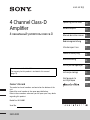
XM-S400D
4 Channel Class-D
Amplifier
4-канальный усилитель класса D
For customers in the United States:
The warranty for this product is included in this manual
(page 13).
Owner’s Record
The model and serial numbers are located on the bottom of the
unit.
Record the serial number in the space provided below.
Refer to these numbers whenever you call upon your Sony dealer
regarding this product.
Model No. XM-S400D
Serial No.
Operating Instructions
GB
Mode d’emploi
FR
Manual de instrucciones
ES
Bedienungsanleitung
DE
Istruzioni per l’uso
IT
Gebruiksaanwijzing
NL
Bruksanvisning
SE
Instruções de operação
PT
Instrukcja obsługi
PL
Инструкция по
эксплуатации
RU
TH

2GB
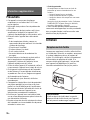
Warning
Made in Thailand
Notice for customers: the following
information is only applicable to equipment
sold in countries applying EU Directives
Manufacturer: Sony Corporation, 1-7-1 Konan
Minato-ku Tokyo, 108-0075 Japan
For EU product compliance: Sony Deutschland
GmbH
, Hedelfinger Strasse 61, 70327 Stuttgart,
Germany
Disposal of waste batteries and
electrical and electronic
equi
pment (applicable in the
European Union and other
European countries with separate
collection systems)
This symbol on the product, the battery or on the
packaging indicates that the product and the
battery shall not be treated as household waste.
On certain batteries this symbol might be used in
co
mbination with a chemical symbol. The chemical
symbols for mercury (Hg) or lead (Pb) are added if
the battery contains more than 0.0005% mercury or
0.004% lead.
By ensuring these products and batteries are
di
sposed of correctly, you will help prevent
potentially negative consequences for the
environment and human health which could
otherwise be caused by inappropriate waste
handling. The recycling of the materials will help to
conserve natural resources.
In case of products that for safety, performance or
da
ta
integrity reasons require a permanent
connection with an incorporated battery, this
battery should be replaced by qualified service staff
only.
To ensure that the battery and the electrical and
ele
ctronic equipment will be treated properly, hand
over these products at end-of-life to the applicable
collection point for the recycling of electrical and
electronic equipment.
For all other batteries, please view the section on
how
to remove the battery from the product safely.
Hand the battery over to the applicable collection
point for the recycling of waste batteries.
For more detailed information about recycling of
this
product or battery, please contact your local
Civic Office, your household waste disposal service
or the shop where you purchased the product or
battery.
FOR THE CUSTOMERS IN THE USA. NOT
APPLICABLE IN CANADA, INCLUDING IN THE
PROVINCE OF QUEBEC.
POUR LES CLIENTS AUX ÉTATS-UNIS. NON
AP
PLIC
ABLE AU CANADA, Y COMPRIS LA
PROVINCE DE QUÉBEC.
This equipment has been tested and found to
comply with the limits for a Class B digital device,
pursuant to Part 15 of the FCC Rules.
These limits are designed to provide reasonable
pr
otection against harmful interference in a
residential installation. This equipment
generates, uses, and can radiate radio frequency
energy and, if not installed and used in
accordance with the instructions, may cause
harmful interference to radio communications.
However, there is no guarantee that interference
wi
ll n
ot occur in a particular installation. If this
equipment does cause harmful interference to
radio or television reception, which can be
determined by turning the equipment off and
on, the user is encouraged to try to correct the
interference by one or more of the following
measures:
R
eorient or relocate the receiving antenna.
Increase the separation between the
eq
uipment and receiver.
Connect the equipment into an outlet on a
c
ircuit different from that to which the receiver
is connected.
Consult the dealer or an experienced radio/TV
te
chnician for help.
You are cautioned that any changes or
mo
difications not expressly approved in this
manual could void your authority to operate this
equipment.

3GB
This symbol is intended to alert the user to
the presence of a hot surface. The symbol
appl
ies to Europe models only.
If you have any questions or problems concerning
your uni
t that are not covered in this manual,
please consult your nearest Sony dealer.
Features
Maximum power output of 100 W per channel (at
4 Ω).
Built-in LP (low-pass) filter and HP (high-pass)
fi
lter.
Protection circuit and indicator provided.
Direct connection can be made with the speaker
outp
ut of your car audio unit if it is not equipped
with the line output (High level input connection).
Hi-level Sensing Power On feature allows this unit
t
o be activated without the need for a REMOTE
connection.
Class-D Technology* is supported.
* Class-D Technology
The Class-D Technology is a method to convert and
am
plify music signals with MOSFETs to high speed
pulse signals. Furthermore, it features high efficiency
and low heat generation.
Table of Contents
Warning . . . . . . . . . . . . . . . . . . . . . . . . . . . . . . . . . . . 2
Features . . . . . . . . . . . . . . . . . . . . . . . . . . . . . . . . . . . 3
Operation
Location and Function of Controls. . . . . . . . . . . . . . 4
Installation and Connections
Parts for Installation and Connections. . . . . . . . . . . 5
Installation . . . . . . . . . . . . . . . . . . . . . . . . . . . . . . . . . 5
Connections . . . . . . . . . . . . . . . . . . . . . . . . . . . . . . . . 6
Power Connections . . . . . . . . . . . . . . . . . . . . . . . 6
Input Connections . . . . . . . . . . . . . . . . . . . . . . . . 7
Speaker Connections . . . . . . . . . . . . . . . . . . . . . 9
Additional Information
Precautions . . . . . . . . . . . . . . . . . . . . . . . . . . . . . . . 10
Maintenance . . . . . . . . . . . . . . . . . . . . . . . . . . . . . . 10
Fuse Replacement. . . . . . . . . . . . . . . . . . . . . . . 10
Specifications. . . . . . . . . . . . . . . . . . . . . . . . . . . . . . 11
Troubleshooting . . . . . . . . . . . . . . . . . . . . . . . . . . . 12
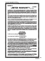
For customers in the United States:
Important notice
The warranty for this product is included in this
manual (page 13). Keep this manual for future
use.

4GB
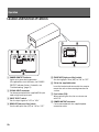
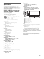
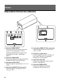
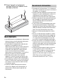
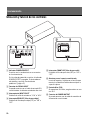
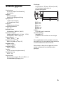
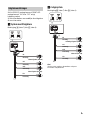
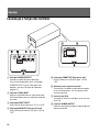
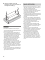
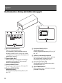
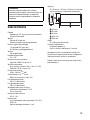
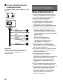
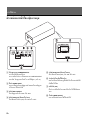
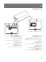
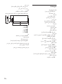
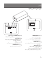
Location and Function of Controls
POWER/PROTECT indicator
Lights up in green during operation.
If the protection circuit activates, the POWER/
PROTECT indicator flashes. For details, see
“Troubleshooting” (page 12).
SIGNAL INPUT connector
C
an be connected with the supplied RCA input
cor
d or high level input cord.
INPUT SELECT switch
Se
ts the input signal to “2CH” or “4CH.”
REAR LPF (low-pass filter) switch
S
ets the low-pass filter (LPF) to “ON” or “OFF.”
FRONT HPF (high-pass filter) switch
S
ets the high-pass filter (HPF) to “ON” or “OFF.”
Slit for the supplied bracket
I
nsert the bracket and secure with the screw to
mo
unt the unit on the mounting board or flat
surface.
Fuse holder (15A)
W
hen replacing the fuse, be sure to use one
wi
th 15 A.
POWER/OUTPUT connector
C
an be connected with the supplied power
co
nnection cable.
Operation

5GB
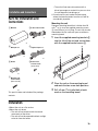
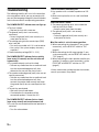
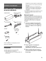
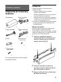
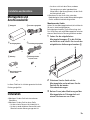
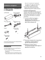
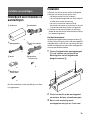
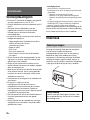
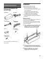
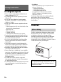
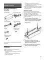
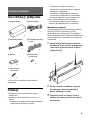
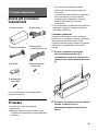
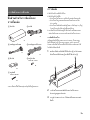
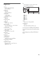
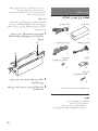
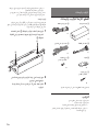
Parts for Installation and
Connections
This parts list does not include all the package
contents.
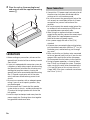
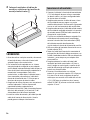
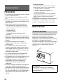
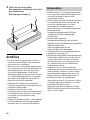
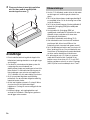
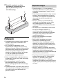
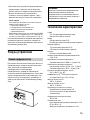
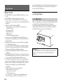
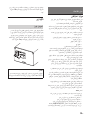
Installation
Mount the unit on a flat surface.
Mount the unit where
The unit will not interfere with the normal
mov
ements of the driver.
The unit will not be exposed to direct sunlight
or
hot air from the heater.
The unit will not come into contact with a
d
river/passengers or materials in your car since
the unit becomes hot during use.
Do not install the unit under the floor carpet,
w
here the heat dissipation from the unit will be
considerably impaired.
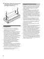
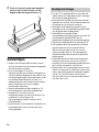
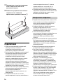
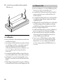
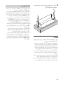
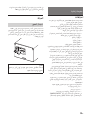
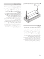
Mounting the unit
Prepare a mounting board that is thicker than 20
mm (
13
/16 in) since the supplied mounting screws
are all 20 mm (
13
/16 in) long. The unit can also be
mounted on the flat surface of your car without a
mounting board.
1 Insert the supplied mounting brackets
into the slits of the unit and secure them
with the supplied bracket screws .
2 Place the unit on the mounting board
and mark the two screw hole positions.
3 Drill a 3 mm (
1
/8 in) pilot hole at each
mark on the mounting board.
Installation and Connections
Main unit
×1
Power connection cable
×1
RCA input cord
×1
High level input cord
×1
Bracket
×2
Bracket screw
ø 2.6 mm × 6 mm
(
1
/8 in ×
1
/4 in)
×2
Mounting screw
ø 4 mm × 20 mm
(
3
/16 in ×
13
/16 in)
×2

6GB
4 Place the unit on the mounting board
and secure it with the supplied mounting
screws .
Connections
Before making any connections, disconnect the
ground (earth) terminal of the car battery to avoid
short circuits.
If your car is equipped with a computer system for
na
vigation or some other purpose, disconnecting
the ground (earth) wire from the car battery may
damage the computer memory. Leaving the
ground (earth) wire connected and disconnecting
the +12 V power supply wire until all the other
wires have been connected may prevent short
circuits.
Be su
re to use speakers with an adequate power
r
ating. If you use small capacity speakers, they
may be damaged.
Do not connect the t
erminal of the speaker
system to the car chassis, and do not connect the
terminal of the right speaker with that of the
left speaker.
Install the input and output cords away from the
p
ower supply wire. Running them close together
may generate interference noise.
C
onnect the +12 V power supply wire only after all
t
he other wires have been connected and the
settings on this unit have been made.
Be sure to connect the ground (earth) wire of the
u
nit securely to a metal point of the car. A loose
connection may cause a malfunction of the
amplifier.
Be sure to connect the remote control wire of the
ca
r audio unit to the remote input (REM) wire of
the supplied power connection cable.
When using a car audio unit without a remote
o
utput for the amplifier, connect the remote input
(REM) wire of the supplied power connection
cable to the accessory power supply.
Use a power supply wire with a fuse (15 A)
at
tached.
All power wires connected to the positive battery
p
ost should be fused within 450 mm (17
3
/4 in) of
the battery post, and before they pass through
any metal.
Make sure that the car’s battery wires connected
to
the car (ground (earth) to chassis) are of a wire
gauge at least equal to that of the main power
wire connected from the battery to the amplifier.
During full-power operation, a current of more
t
han 15 A will run through the system. Therefore,
make sure that the wires to be connected to the
+12 V and GND wires of this unit are at least 14-
Ga
uge (AWG-14) or have a sectional area of more
than 2 mm² (
3
/32 in²).
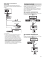
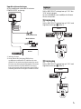
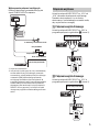
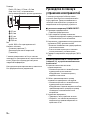
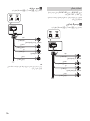
Power Connections

7GB
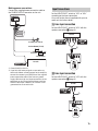
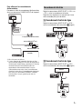
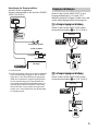
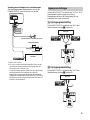
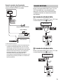
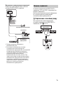
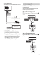
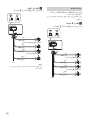
Making power connections
Connect the supplied power connection cable to
the POWER/OUTPUT connector on the unit.
*1 Ground (earth) to chassis.
*2 If you have the factory original or some other car
audio
unit without a remote output for the amplifier,
connect the remote input (REM) wire of the supplied
power connection cable to the accessory power
supply. With the high level input connection, the car
audio unit can also be activated without need for a
REMOTE connection. However, this function is not
guaranteed for all car audio units.
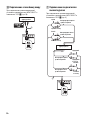
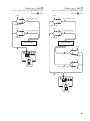
Set the INPUT SELECT switch to “2CH” or “4CH”
according to the input connection.
Also, refer to the manual supplied with your car
au
dio unit for further details.
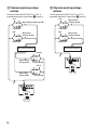
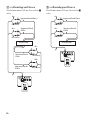
Line input connection
Set the INPUT SELECT switch to “4CH” with the
speaker connection (page 9).
Line input connection
Set the INPUT SELECT switch to “2CH” with the
speaker connection (page 9).
to a metal point of the car
less than 450 mm (17
3
/4 in)
Fuse (15 A)
+12 V car battery
Car audio
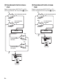
Input Connections
Car audio
Car audio

8GB
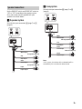
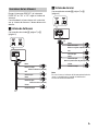
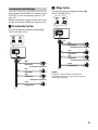
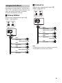
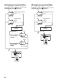
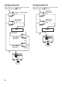
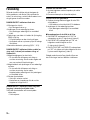
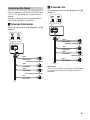
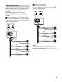
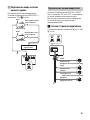
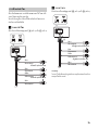
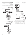
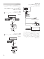
High level input connection
Set the INPUT SELECT switch to “4CH” with the
speaker connection (page 9).
High level input connection
Set the INPUT SELECT switch to “2CH” with the
speaker connection (page 9).
Gray
Gray/Striped
Front right speaker output
White
White/Striped
Front left speaker output
Car audio
Purple
Purple/Striped
Rear right speaker output
Rear left speaker output
Green
Green/Striped
Gray
Gray/Striped
White
White/Striped
Front right speaker output
Front left speaker output
Car audio

9GB
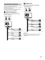
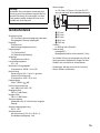
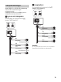
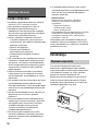
Set the REAR LPF switch and FRONT HPF switch to
“ON” or “OFF” according to the speaker system.
Also, refer to the manual supplied with your
sp
eakers for further details.
4-speaker system
Set with the input connection (page 7) or
(page 8).
2-way system
Set with the input connection (page 7) or
(page 8).
Note
In this system, the volume of the subwoofer will be
co
ntrolled by the car audio unit fader control.
Speaker Connections
White
White/Striped
Gray
Gray/Striped
Green
Green/Striped
Purple
Purple/Striped
Front speakers (min. 4 Ω)
Rear speakers (min. 4 Ω)
White
White/Striped
Gray
Gray/Striped
Green
Green/Striped
Purple
Purple/Striped
Full range speakers (min. 4 Ω)
Subwoofers (min. 4 Ω)

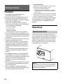
10GB
Precautions
This unit is designed for negative ground (earth)
12 V DC operation only.
Use speakers with an impedance of 4 Ω to 8 Ω.
Do not connect any active speakers (with built-in
a
mplifiers) to the unit. Doing so may damage the
active speakers.
Avoid installing the unit in areas subject to:
High temperatures such as from direct sunlight
or
hot air from the heater
Rain or moisture
Dust or dirt
Inclined surface
Direct contact with a driver/passengers.
If your car is parked in direct sunlight and there is
a c
onsiderable rise in temperature inside the car,
allow the unit to cool down before use.
When installing the unit horizontally, be sure not
t
o cover the unit with the floor carpet, etc.
If this unit is placed too close to the car audio unit
o
r antenna (aerial), interference may occur. In this
case, relocate this unit away from the car audio
unit or antenna (aerial).
I
f no power is being supplied to the car audio
uni
t, check the connections.
This unit employs a protection circuit* to protect
t
he transistors and speakers if the amplifier
malfunctions. Do not attempt to test the
protection circuits by covering the unit or
connecting improper loads.
Do no
t use the unit on a weak battery as its
op
timum performance depends on a good power
supply.
For safety, keep your car audio unit volume
moder
ate so that you can still hear other sounds.
* Protection circuit
This amplifier is provided with a protection circuit that
op
erates in the following cases:
When the unit overheats
When a DC current is generated
When the speaker terminals are short-circuited.
If a pr
otection circuit is activated, the POWER/
PR
OTECT indicator will flash. For details, see
“Troubleshooting” (page 12).
If you have any questions or problems concerning
your unit that are not covered in this manual,
please consult your nearest Sony dealer.
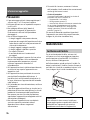
Maintenance
When replacing the fuse, be sure to use one
matching the amperage stated above the fuse
holder. If the fuse blows, check the power
connection and replace the fuse. If the fuse blows
again after replacement, there may be an internal
malfunction. In such a case, consult your nearest
Sony dealer.
Additional Information
Fuse Replacement
Warning
Never use a fuse with an amperage rating
exceeding the one supplied with the unit as this
could damage the unit.

11GB
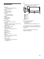
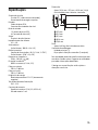
Specifications
FOR THE CUSTOMERS IN THE USA. NOT
APPLICABLE IN CANADA, INCLUDING IN THE
PROVINCE OF QUEBEC.
POUR LES CLIENTS AUX ÉTATS-UNIS. NON
AP
PLIC
ABLE AU CANADA, Y COMPRIS LA
PROVINCE DE QUÉBEC.
AUDIO POWER SPECIFICATIONS
CEA2006 Standard
Power Output: 45 Watts RMS × 4 at
4 Ohms < 1% THD+N
SN Ratio: 83 dBA
(reference: 1 Watt into 4 Ohms)
Circuit system
OTL (output transformerless) circuit,
Pulse power supply
Inputs
RCA pin jacks,
High level input connector
Input level
1 V (RCA pin jacks),
8 V (High level input)
Outputs
Speaker terminals
Speaker impedance
4 Ω – 8 Ω
Maximum output
4 Speakers: 100 W × 4 (at 4 Ω)
Rated output
(supply voltage at 14.4 V, 1 kHz, 1% THD)
4 Speakers: 45 W × 4 (at 4 Ω)
Frequency response
20 Hz – 20 kHz ( dB)
Harmonic distortion
0.08% or less (at 1 kHz, 4 Ω)
Low-pass filter
120 Hz, 12 dB/oct
High-pass filter
120 Hz, 12 dB/oct
Power requirements
12 V DC car battery (negative ground (earth))
Power supply voltage
10.5 V – 16 V
Current drain
At rated output: 15 A (4 Ω, 45 W × 4)
Remote input: 1 mA
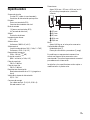
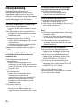
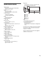
Dimensions
Approx. 162.8 mm × 37.3 mm × 62.6 mm
(6
1
/2 in × 1
1
/2 in × 2
1
/2 in) (w/h/d) not incl.
projecting parts and controls
37.3 mm (1
1
/2 in)
62.6 mm (2
1
/2 in)
31.3 mm (1
1
/4 in)
162.8 mm (6
1
/2 in)
176.8 mm (7 in)
Ma
ss
Approx. 0.46 kg (1
1
/64 lb) not incl. accessories
Package contents:
Main unit (1)
Parts for installation and connections (1 set)
Your dealer may not handle some of the above
l
i
sted accessories. Please ask the dealer for detailed
information.
Design and specifications are subject to change
wit
hout notice.
+0.5
−
3.0

12GB
Troubleshooting
The following checklist will assist in the correction
of most problems which you may encounter with
your unit. Before going through the checklist below,
refer to the connection and operating procedures.
The POWER/PROTECT indicator does not light up.
The fuse is blown.
Replace the fuse with a new one.
The ground (earth) wire is not securely
c
onnected.
Fasten the ground (earth) wire securely to a
m
etal point of the car.
The voltage going into the remote input (REM)
w
ire is too low.
Turn on the car audio unit if it is not turned on.
Use a relay if the system employs too many
amp
lifiers.
Check the battery voltage (10.5 V – 16 V).
The POWER/PROTECT indicator flashes quickly
(once every 0.2 seconds) and the unit turns off
automatically.
The speaker outputs are short circuited.
Take out any media from the car audio unit and
t
urn the connected equipment off, then
determine the cause of the short circuits.
The speaker cord and ground (earth) wire are not
se
curely connected.
Take out any media from the car audio unit and
t
urn the connected equipment off, then
connect the speaker cord securely and fasten
the ground (earth) wire to a metal point of the
car.
The unit has overheated.
Wait until the unit cools down.
Check whether the impedance of the
c
onnected speakers is lower than 4 Ω.
The POWER/PROTECT indicator flashes slowly
(once every second) and sound becomes low.
The unit has overheated and thermal protector is
activated.
Turn the volume down.
The unit becomes abnormally hot.
Use speakers with a suitable impedance of 4 Ω -
8 Ω.
Make sure to place the unit in a well ventilated
lo
cation.
Alternator noise is heard.
The power connecting wires are installed too
close to the RCA pin cords.
Keep the wires away from the cords.
The ground (earth) wire is not securely
co
nnected.
Fasten the ground (earth) wire securely to a
m
etal point of the car.
The filter switch is set to the wrong position.
When connecting the subwoofer (2-way system
connection), set the REAR LPF switch to “ON”
(page 9).
When connecting the full range speaker (2-way
sy
stem connection), set the FRONT HPF switch to
“ON” (page 9).
When connecting the front speakers and the rear
s
peakers (4-speaker system connection), set the
FRONT HPF and REAR LPF switches to “OFF”
(page 9).
If these solutions do not help improve the situation,
co
nsult your nearest Sony dealer.

13GB

2FR
Fabriqué en Thaïlande
Avis à l’attention des clients : les informations
suivantes s’appliquent uniquement aux
appareils vendus dans des pays qui
appliquent les directives de l’Union
Européenne
Fabricant : Sony Corporation, 1-7-1 Konan Minato-ku
Tokyo, 108-0075 Japon
Pour toute question relative à la conformité des
pr
oduits dans l’UE : Sony Deutschland GmbH,
Hedelfinger Strasse 61, 70327 Stuttgart, Allemagne
Elimination des piles et
accumulateurs et des
Equi
pements Electriques et
Electroniques usagés (Applicable
dans les pays de l’Union
Européenne et aux autres pays européens
disposant de systèmes de collecte sélective)
Ce symbole apposé sur le produit, la pile ou
l’accumulateur ou sur l’emballage, indique que le
produit et les piles et accumulateurs fournis avec ce
produit ne doivent pas être traités comme de
simples déchets ménagers.
Sur certains types de piles, ce symbole apparaît
pa
rfois combiné avec un symbole chimique. Les
symboles pour le mercure (Hg) ou le plomb (Pb)
sont rajoutés lorsque ces piles contiennent plus de
0,0005% de mercure ou 0,004% de plomb.
En vous assurant que les produits, piles et
acc
umulateurs sont mis au rebut de façon
appropriée, vous participez activement à la
prévention des conséquences négatives que leur
mauvais traitement pourrait provoquer sur
l’environnement et sur la santé humaine. Le
recyclage des matériaux contribue par ailleurs à la
préservation des ressources naturelles.
Pour les produits qui pour des raisons de sécurité,
d
e p
erformance ou d’intégrité de données
nécessitent une connexion permanente à une pile
ou à un accumulateur, il conviendra de vous
rapprocher d’un Service Technique qualifié pour
effectuer son remplacement.
En rapportant votre appareil électrique, les piles et
a
c
cumulateurs en fin de vie à un point de collecte
approprié vous vous assurez que le produit, la pile
ou l’accumulateur incorporé sera traité
correctement.
Pour tous les autres cas de figure et afin d’enlever
l
e
s piles ou accumulateurs en toute sécurité de
votre appareil, reportez-vous au manuel
d’utilisation. Rapportez les piles et accumulateurs,
et les équipements électriques et électroniques
usagés au point de collecte approprié pour le
recyclage.
Pour toute information complémentaire au sujet du
r
e
cyclage de ce produit ou des piles et
accumulateurs, vous pouvez contacter votre
municipalité, votre déchetterie locale ou le point de
vente où vous avez acheté ce produit.
Ce symbole alerte l’utilisateur de la
présence d’une surface chaude. Il ne
s
’
applique qu’aux modèles européens.
Si vous avez des questions ou des problèmes
co
ncernant votre appareil qui ne sont pas abordés
dans ce mode d’emploi, veuillez consulter votre
détaillant Sony le plus proche.

3FR
Caractéristiques
Puissance de sortie maximale de 100 W par canal
(à 4 Ω).
Filtre passe-bas (LP) et filtre passe-haut (HP)
int
égrés.
Circuit et indicateur de protection.
Un raccordement direct est possible avec la sortie
de
haut-parleur de votre autoradio si celui-ci n’est
pas équipé d’une sortie de ligne (raccordement
d’entrée à niveau élevé).
Une fonction de mise en marche par détection de
ni
veau élevé permet à cet appareil d’être activé
sans raccordement REMOTE.
Prise en charge de la technologie de classe D*
.
* Technologie de classe D
La technologie de classe D est une méthode
perme
ttant de convertir et d’amplifier des signaux
musicaux grâce à des MOSFET pour obtenir des
signaux par impulsion à grande vitesse. De plus, elle
permet d’obtenir une efficacité élevée et un
dégagement de chaleur faible.
Table des matières
Caractéristiques. . . . . . . . . . . . . . . . . . . . . . . . . . . . . 3
Utilisation
Emplacement et fonction des commandes . . . . . . 4
Installation et raccordements
Pièces destinées à l’installation et aux
raccordements. . . . . . . . . . . . . . . . . . . . . . . . . . . 5
Installation . . . . . . . . . . . . . . . . . . . . . . . . . . . . . . . . . 5
Raccordements . . . . . . . . . . . . . . . . . . . . . . . . . . . . . 6
Raccordements d’alimentation . . . . . . . . . . . . . 6
Raccordements d’entrée. . . . . . . . . . . . . . . . . . . 7
Raccordement des haut-parleurs. . . . . . . . . . . . 9
Informations supplémentaires
Précautions . . . . . . . . . . . . . . . . . . . . . . . . . . . . . . . 10
Entretien. . . . . . . . . . . . . . . . . . . . . . . . . . . . . . . . . . 10
Remplacement du fusible. . . . . . . . . . . . . . . . . 10
Caractéristiques techniques . . . . . . . . . . . . . . . . . . 11
Dépannage . . . . . . . . . . . . . . . . . . . . . . . . . . . . . . . 12

4FR
Emplacement et fonction des commandes
Indicateur POWER/PROTECT
S’allume en vert en cours de fonctionnement.
Lorsque le circuit de protection s’active,
l’indicateur POWER/PROTECT clignote. Pour
plus de détails, consultez « Dépannage »
(page 12).
C
onnecteur SIGNAL INPUT
P
ermet le raccordement du cordon d’entrée RCA
ou co
rdon d’entrée à niveau élevé fourni.
Commutateur INPUT SELECT
P
ermet de régler le signal d’entrée à « 2CH » ou
« 4CH ».
Commutateur REAR LPF (filtre passe-bas)
P
ermet de régler le filtre passe-bas (LPF) à
« ON » ou « OFF ».
Commutateur FRONT HPF (filtre passe-haut)
P
ermet de régler le filtre passe-haut (HPF) à
« ON » ou « OFF ».
Fente pour le support fourni
I
nsérez le support et fixez-le à l’aide de la vis
po
ur installer l’appareil sur la plaque de
montage ou une surface plate.
Support de fusible (15A)
L
orsque vous remplacez le fusible, veillez à
ut
iliser un fusible de 15 A.
Connecteur POWER/OUTPUT
P
ermet le raccordement du câble de
rac
cordement d’alimentation fourni.
Utilisation

5FR
Pièces destinées à l’installation
et aux raccordements
Cette liste de pièces ne comprend pas tout le
contenu de l’emballage.
Installation
Installez l’appareil sur une surface plate.
Installez l’appareil à un endroit où
L’appareil ne gênera pas le conducteur dans ses
mouv
ements.
L’appareil ne sera pas exposé au rayonnement
dir
ect du soleil ou à l’air chaud du système de
chauffage.
L’appareil n’entrera pas en contact avec le
c
onducteur/les passagers ou des objets dans
votre voiture, car il devient chaud pendant
l’utilisation.
N’installez pas l’appareil sous le tapis de sol, car la
dis
sipation thermique ne pourrait pas se faire
correctement.
Montage de l’appareil
Préparez une plaque de montage d’une épaisseur
supérieure à 20 mm (
13
/16 po), car la longueur des
vis de montage fournies est de 20 mm (
13
/16 po).
L’appareil peut également être installé sur une
surface plate de votre voiture, sans plaque de
montage.
1 Insérez les supports de montage
fournis dans les fentes de l’appareil et
fixez-les à l’aide des vis de support
fournies.
2 Placez l’appareil sur la plaque de
montage, puis marquez les
emplacements des deux orifices de vis.
3 Percez un orifice de 3 mm (
1
/8 po) au
niveau de chaque repère sur la plaque
de montage.
Installation et raccordements
Appareil principal
×1
Câble de raccordement
d’alimentation
×1
Cordon d’entrée RCA
×1
Cordon d’entrée à niveau
élevé
×1
Support
×2
Vis de support
ø 2,6 mm × 6 mm
(
1
/8 po ×
1
/4 po)
×2
Vis de montage
ø 4 mm × 20 mm
(
3
/16 po ×
13
/16 po)
×2

6FR
4 Placez l’appareil sur la plaque de
montage et fixez-le à l’aide des vis de
montage fournies.
Raccordements
Avant d’effectuer les raccordements, déconnectez
la borne de masse de la batterie de voiture pour
éviter de provoquer un court-circuit.
Si votre voiture est équipée d’un ordinateur de
b
ord pour la navigation ou autre, le
débranchement du fil de masse de la batterie de
voiture pourrait endommager la mémoire de
l’ordinateur. Pour réduire les risques de court-
circuit, laissez le fil de masse raccordé et
déconnectez le fil d’alimentation +12 V jusqu’à ce
q
u
e tous les autres fils aient été raccordés.
Utilisez des haut-parleurs d’une capacité
a
déquate. Si vous utilisez des haut-parleurs de
faible capacité, ils risquent d’être endommagés.
Ne raccordez pas la borne d
u système de haut-
parleurs au châssis de la voiture et ne raccordez
pas la borne du haut-parleur droit à celle du
haut-parleur gauche.
Installez les cordons d’entrée et de sortie en
v
eillant à les éloigner du fil d’alimentation. La
proximité de ce dernier pourrait générer des
interférences.
R
accordez le fil d’alimentation +12 V
uniquement
après avoir raccordé tous les autres fils et effectué
les réglages sur cet appareil.
Veillez à raccorder solidement le fil de masse de
l
’appareil à un point métallique de la voiture. Un
raccordement incorrect pourrait causer un
problème de fonctionnement de l’amplificateur.
Veillez à raccorder le fil de commande à distance
de
l’autoradio au fil d’entrée de commande à
distance (REM) du câble de raccordement
d’alimentation fourni.
Si vous utilisez un autoradio dépourvu de sortie
de
commande à distance pour l’amplificateur,
raccordez le fil d’entrée de commande à distance
(REM) du câble de raccordement d’alimentation
fourni à la prise d’alimentation accessoires.
U
tilisez un fil d’alimentation doté d’un fusible
(15 A).
Tous les fils d’alimentation raccordés à la borne
po
sitive de la batterie doivent être protégés par
un fusible à une distance maximale de 450 mm
(17
3
/4 po) de la borne de batterie et avant de
passer dans une partie métallique quelconque.
Assurez-vous que les fils de batterie raccordés à
la
voiture (mise à la masse au châssis) sont d’un
calibre au moins égal à celui du fil d’alimentation
principal permettant de raccorder la batterie à
l’amplificateur.
Pendant le fonctionnement à pleine puissance,
u
n courant de plus de 15 A circule dans le
sys
tème. Par conséquent, assurez-vous que les
fils à raccorder aux fils +12 V et GND de cet
appa
reil sont de calibre égal ou supérieur à 14
(AWG-14) ou qu’ils possèdent une zone
sectionnelle supérieure à 2 mm² (
3
/32 po²).
Raccordements d’alimentation

7FR
Pour effectuer les raccordements
d’alimentation
Raccordez le câble de raccordement d’alimentation
fourni au connecteur POWER/OUTPUT de l’appareil.
*1 Mise à la masse au châssis.
*2 Si vous disposez de l’autoradio d’origine ou d’un
autre
autoradio dépourvu de sortie de commande à
distance pour l’amplificateur, raccordez le fil d’entrée
de commande à distance (REM) du câble de
raccordement d’alimentation fourni à la prise
d’alimentation accessoires. Avec le raccordement
d’entrée à niveau élevé, l’autoradio peut également
être activé sans raccordement REMOTE. Toutefois,
cette fonction n’est pas garantie pour tous les
autoradios.
Réglez le commutateur INPUT SELECT à « 2CH » ou
« 4CH », selon le raccordement d’entrée.
Reportez-vous également au manuel fourni avec
votr
e autoradio pour plus de détails.
Raccordement d’entrée de ligne
Réglez le commutateur INPUT SELECT à « 4CH »
avec le raccordement de haut-parleur (page 9).
Raccordement d’entrée de ligne
Réglez le commutateur INPUT SELECT à « 2CH »
avec le raccordement de haut-parleur (page 9).
à un point métallique de la voiture
moins de 450 mm (17
3
/4 po)
Fusible (15 A)
Batterie de voiture +12 V
Autoradio
Raccordements d’entrée
Autoradio
Autoradio

8FR
Raccordement d’entrée à niveau
élevé
Réglez le commutateur INPUT SELECT à « 4CH »
avec le raccordement de haut-parleur (page 9).
Raccordement d’entrée à niveau
élevé
Réglez le commutateur INPUT SELECT à « 2CH »
avec le raccordement de haut-parleur (page 9).
Gris
Gris/Rayé
Sortie de haut-parleur avant droit
Blanc
Blanc/Rayé
Sortie de haut-parleur
avant gauche
Autoradio
Violet
Violet/Rayé
Sortie de haut-parleur
arrière droit
Sortie de haut-parleur
arrière gauche
Vert
Vert/Rayé
Gris
Gris/Rayé
Blanc
Blanc/Rayé
Sortie de haut-parleur avant droit
Sortie de haut-parleur
avant gauche
Autoradio
A página está carregando...
A página está carregando...
A página está carregando...
A página está carregando...
A página está carregando...
A página está carregando...
A página está carregando...
A página está carregando...
A página está carregando...
A página está carregando...
A página está carregando...
A página está carregando...
A página está carregando...
A página está carregando...
A página está carregando...
A página está carregando...
A página está carregando...
A página está carregando...
A página está carregando...
A página está carregando...
A página está carregando...
A página está carregando...
A página está carregando...
A página está carregando...
A página está carregando...
A página está carregando...
A página está carregando...
A página está carregando...
A página está carregando...
A página está carregando...
A página está carregando...
A página está carregando...
A página está carregando...
A página está carregando...
A página está carregando...
A página está carregando...
A página está carregando...
A página está carregando...
A página está carregando...
A página está carregando...
A página está carregando...
A página está carregando...
A página está carregando...
A página está carregando...
A página está carregando...
A página está carregando...
A página está carregando...
A página está carregando...
A página está carregando...
A página está carregando...
A página está carregando...
A página está carregando...
A página está carregando...
A página está carregando...
A página está carregando...
A página está carregando...
A página está carregando...
A página está carregando...
A página está carregando...
A página está carregando...
A página está carregando...
A página está carregando...
A página está carregando...
A página está carregando...
A página está carregando...
A página está carregando...
A página está carregando...
A página está carregando...
A página está carregando...
A página está carregando...
A página está carregando...
A página está carregando...
A página está carregando...
A página está carregando...
A página está carregando...
A página está carregando...
A página está carregando...
A página está carregando...
A página está carregando...
A página está carregando...
A página está carregando...
A página está carregando...
A página está carregando...
A página está carregando...
A página está carregando...
A página está carregando...
A página está carregando...
A página está carregando...
A página está carregando...
A página está carregando...
A página está carregando...
A página está carregando...
A página está carregando...
A página está carregando...
A página está carregando...
A página está carregando...
A página está carregando...
A página está carregando...
A página está carregando...
A página está carregando...
A página está carregando...
A página está carregando...
A página está carregando...
A página está carregando...
A página está carregando...
A página está carregando...
A página está carregando...
A página está carregando...
A página está carregando...
A página está carregando...
A página está carregando...
A página está carregando...
A página está carregando...
A página está carregando...
A página está carregando...
A página está carregando...
A página está carregando...
A página está carregando...
A página está carregando...
A página está carregando...
A página está carregando...
A página está carregando...
A página está carregando...
A página está carregando...
A página está carregando...
A página está carregando...
A página está carregando...
A página está carregando...
A página está carregando...
A página está carregando...
A página está carregando...
A página está carregando...
A página está carregando...
A página está carregando...
A página está carregando...
A página está carregando...
A página está carregando...
A página está carregando...
A página está carregando...
A página está carregando...
-
 1
1
-
 2
2
-
 3
3
-
 4
4
-
 5
5
-
 6
6
-
 7
7
-
 8
8
-
 9
9
-
 10
10
-
 11
11
-
 12
12
-
 13
13
-
 14
14
-
 15
15
-
 16
16
-
 17
17
-
 18
18
-
 19
19
-
 20
20
-
 21
21
-
 22
22
-
 23
23
-
 24
24
-
 25
25
-
 26
26
-
 27
27
-
 28
28
-
 29
29
-
 30
30
-
 31
31
-
 32
32
-
 33
33
-
 34
34
-
 35
35
-
 36
36
-
 37
37
-
 38
38
-
 39
39
-
 40
40
-
 41
41
-
 42
42
-
 43
43
-
 44
44
-
 45
45
-
 46
46
-
 47
47
-
 48
48
-
 49
49
-
 50
50
-
 51
51
-
 52
52
-
 53
53
-
 54
54
-
 55
55
-
 56
56
-
 57
57
-
 58
58
-
 59
59
-
 60
60
-
 61
61
-
 62
62
-
 63
63
-
 64
64
-
 65
65
-
 66
66
-
 67
67
-
 68
68
-
 69
69
-
 70
70
-
 71
71
-
 72
72
-
 73
73
-
 74
74
-
 75
75
-
 76
76
-
 77
77
-
 78
78
-
 79
79
-
 80
80
-
 81
81
-
 82
82
-
 83
83
-
 84
84
-
 85
85
-
 86
86
-
 87
87
-
 88
88
-
 89
89
-
 90
90
-
 91
91
-
 92
92
-
 93
93
-
 94
94
-
 95
95
-
 96
96
-
 97
97
-
 98
98
-
 99
99
-
 100
100
-
 101
101
-
 102
102
-
 103
103
-
 104
104
-
 105
105
-
 106
106
-
 107
107
-
 108
108
-
 109
109
-
 110
110
-
 111
111
-
 112
112
-
 113
113
-
 114
114
-
 115
115
-
 116
116
-
 117
117
-
 118
118
-
 119
119
-
 120
120
-
 121
121
-
 122
122
-
 123
123
-
 124
124
-
 125
125
-
 126
126
-
 127
127
-
 128
128
-
 129
129
-
 130
130
-
 131
131
-
 132
132
-
 133
133
-
 134
134
-
 135
135
-
 136
136
-
 137
137
-
 138
138
-
 139
139
-
 140
140
-
 141
141
-
 142
142
-
 143
143
-
 144
144
-
 145
145
-
 146
146
-
 147
147
-
 148
148
-
 149
149
-
 150
150
-
 151
151
-
 152
152
-
 153
153
-
 154
154
-
 155
155
-
 156
156
-
 157
157
-
 158
158
-
 159
159
-
 160
160


Sony XM-S400D//Q Manual do usuário
- Categoria
- Alto-falantes do carro
- Tipo
- Manual do usuário
em outras línguas
- Nederlands: Sony XM-S400D//Q Handleiding
Artigos relacionados
-
Sony XM-S400D Manual do proprietário
-
Sony XM-604M Manual do usuário
-
Sony XM-GTX6040 Manual do usuário
-
Sony XM-N1004 Instruções de operação
-
Sony XM-752EQX Instruções de operação
-
-
Sony XM-N502 Instruções de operação
-
Sony XM-ZR602 Instruções de operação
-
-
Sony XS-AW200X Manual do proprietário