
AI1
AO1
GND
+10 V
DO2-TR
rpm
B - RS485
+24 V
>300 Ω
+24 V
DO1-RL -NO
DO1-RL -C
DO1-RL -NC
DI1
DI2
DI3
DI4
A - RS485
≥5 kΩ
GND
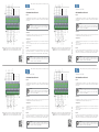
Figure 1: Signals of the connector of the CFW500-IOS-PNP plug-in module
Figura 1: Señales del conector del módulo plugin CFW500-IOS-PNP
Figura 1: Sinais do conector do módulo plug-in CFW500-IOS-PNP
Document: 10004952984 / 00
14017818
CFW500-IOS -PNP
Addendum/Anexo/Adendo
English
This addendum indicates the differences of the CFW500-IOS-PNP plug-in from the
standard CFW500-IOS plug-in, whose information is found in the CFW500 or MW500
user’s manual.
NOTE!
The CFW500-IOS-PNP accessory must be only used with the main
software version equal to or above the version V2.05 for the CFW500
or version V2.00 for the MW500.
Installation:
After plugging the CFW500-IOS-PNP accessory into place, energize the inverter and
check that parameter P0027 indicates value 13 (P0027 = 13).
Configurations:
- Digital inputs are fixed at active high (P0271 = 8). It is not possible to change P0271
different from 8.
- The other configurations described in item 3.2.5 of the manual are valid for the
CFW500-IOS-PNP.
Español
Este anexo presenta las diferencias para el plugin CFW500-IOS-PNP con relación al
plugin estándar CFW500-IOS. Las informaciones referentes al plug-in estándar
CFW500-IOS se encuentran descritas en el manual del usuario CFW500 o MW500.
¡NOTA!
El accesorio CFW500-IOS-PNP debe ser utilizado solamente con la
Versión de software principal igual o superior a la versión V2.05 para
el CFW500 o versión V2.00 para el MW500 .
Motors | Automation | Energy | Transmission & Distribution | Coatings
CFW500-IOS -PNP
Addendum/Anexo/Adendo
English
This addendum indicates the differences of the CFW500-IOS-PNP plug-in from the
standard CFW500-IOS plug-in, whose information is found in the CFW500 or MW500
user’s manual.
NOTE!
The CFW500-IOS-PNP accessory must be only used with the main
software version equal to or above the version V2.05 for the CFW500
or version V2.00 for the MW500.
Installation:
After plugging the CFW500-IOS-PNP accessory into place, energize the inverter and
check that parameter P0027 indicates value 13 (P0027 = 13).
Configurations:
- Digital inputs are fixed at active high (P0271 = 8). It is not possible to change P0271
different from 8.
- The other configurations described in item 3.2.5 of the manual are valid for the
CFW500-IOS-PNP.
Español
Este anexo presenta las diferencias para el plugin CFW500-IOS-PNP con relación al
plugin estándar CFW500-IOS. Las informaciones referentes al plug-in estándar
CFW500-IOS se encuentran descritas en el manual del usuario CFW500 o MW500.
¡NOTA!
El accesorio CFW500-IOS-PNP debe ser utilizado solamente con la
Versión de software principal igual o superior a la versión V2.05 para
el CFW500 o versión V2.00 para el MW500.
AI1
AO1
GND
+10 V
DO2-TR
rpm
B - RS485
+24 V
>300 Ω
+24 V
DO1-RL -NO
DO1-RL -C
DO1-RL -NC
DI1
DI2
DI3
DI4
A - RS485
≥5 kΩ
GND
Figure 1: Signals of the connector of the CFW500-IOS-PNP plug-in module
Figura 1: Señales del conector del módulo plugin CFW500-IOS-PNP
Figura 1: Sinais do conector do módulo plug-in CFW500-IOS-PNP
Document: 10004952984 / 00
14017818
CFW500-IOS -PNP
Addendum/Anexo/Adendo
English
This addendum indicates the differences of the CFW500-IOS-PNP plug-in from the
standard CFW500-IOS plug-in, whose information is found in the CFW500 or MW500
user’s manual.
NOTE!
The CFW500-IOS-PNP accessory must be only used with the main
software version equal to or above the version V2.05 for the CFW500
or version V2.00 for the MW500.
Installation:
After plugging the CFW500-IOS-PNP accessory into place, energize the inverter and
check that parameter P0027 indicates value 13 (P0027 = 13).
Configurations:
- Digital inputs are fixed at active high (P0271 = 8). It is not possible to change P0271
different from 8.
- The other configurations described in item 3.2.5 of the manual are valid for the
CFW500-IOS-PNP.
Español
Este anexo presenta las diferencias para el plugin CFW500-IOS-PNP con relación al
plugin estándar CFW500-IOS. Las informaciones referentes al plug-in estándar
CFW500-IOS se encuentran descritas en el manual del usuario CFW500 o MW500.
¡NOTA!
El accesorio CFW500-IOS-PNP debe ser utilizado solamente con la
Versión de software principal igual o superior a la versión V2.05 para
el CFW500 o versión V2.00 para el MW500.
Motors | Automation | Energy | Transmission & Distribution | Coatings
CFW500-IOS -PNP
Addendum/Anexo/Adendo
English
This addendum indicates the differences of the CFW500-IOS-PNP plug-in from the
standard CFW500-IOS plug-in, whose information is found in the CFW500 or MW500
user’s manual.
NOTE!
The CFW500-IOS-PNP accessory must be only used with the main
software version equal to or above the version V2.05 for the CFW500
or version V2.00 for the MW500.
Installation:
After plugging the CFW500-IOS-PNP accessory into place, energize the inverter and
check that parameter P0027 indicates value 13 (P0027 = 13).
Configurations:
- Digital inputs are fixed at active high (P0271 = 8). It is not possible to change P0271
different from 8.
- The other configurations described in item 3.2.5 of the manual are valid for the
CFW500-IOS-PNP.
Español
Este anexo presenta las diferencias para el plugin CFW500-IOS-PNP con relación al
plugin estándar CFW500-IOS. Las informaciones referentes al plug-in estándar
CFW500-IOS se encuentran descritas en el manual del usuario CFW500 o MW500.
¡NOTA!
El accesorio CFW500-IOS-PNP debe ser utilizado solamente con la
Versión de software principal igual o superior a la versión V2.05 para
el CFW500 o versión V2.00 para el MW500.
Motors | Automation | Energy | Transmission & Distribution | Coatings

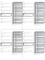
Connector/Conector Description/Descripción/Descrição
(**)
Top connection/Borne superior
1 DI1 Digital input 1/ Entrada digital 1
3 DI2 Digital input 2/ Entrada digital 2
5 DI3 Digital input 3/ Entrada digital 3
7 DI4 Digital input 4/ Entrada digital 4
9 +24 V Power supply +24 Vdc/ Fuente +24 Vcc/
11 DO1-RL-NO
Digital output 1 (NO contact of relay 1)/ Salida
digital 1 (Contacto NA del relé)/ Saída digital 1
(Contato NA do relé 1)
13 DO1-RL-C
Digital output 1 (Common point of relay 1)/ Salida
digital 1 (Punto común del relé 1)/
15 DO1-RL-NC
Digital output 1 (NC contact of relay 1)/ Salida
digital 1 (Punto común del relé 1)/ Saída digital 1
(Ponto comum do relé 1)
Bottom connection/Borne inferior
2 AO1 Analog output 1/ Salida analógica 1/ Saída digital 1
4 GND Reference 0 V/ Referencia 0 V/ Referência 0 V
6 AI1 Analog input 1/ Entrada analógica 1
8 +10 V
Reference +10 Vdc for potentiometer/ Referencia
+10 Vcc para potenciómetro/ Referência +10 Vcc
para potenciômetro
10 DO2-TR
Digital output 2 (transistor)/ Salida digital 2
(Transistor)/ Saída digital 2 (transistor)
12 RS485 - A RS485 (terminal A)
14 RS485 - B RS485 (terminal B)
16 GND Reference 0 V/ Referencia 0 V/ Referência 0 V
(**) For more information see the detailed specification in Section 8.2 ELECTRONICS/GENERAL DATA of the
user manual CFW500.
(**) Para más informaciones consulte la especificación detallada en la Sección 8.2 DATOS DE LA
ELECTRÓNICA/GENERALES del manual del usuario CFW500.
(**) Para mais informações consulte a especificação detalhada na Seção 8.2 DADOS DA ELETRÔNICA/
GERAIS do manual do usuário CFW500.
Instalación:
Luego de encajar el accesorio CFW500-IOS-PNP, energice el convertidor y verifique si
el parámetro P0027 indica el valor 13 (P0027 = 13).
Configuraciones:
- Las entradas digitales son fijadas en activo alto (P0271 = 8). No es posible alterar
P0271 diferente de 8.
- Las demás configuraciones descritas en el ítem 3.2.5 del manual son válidas para el
CFW500-IOS-PNP.
Português
Este adendo apresenta as diferenças para o plug-in CFW500-IOS-PNP em relação ao
plug-in padrão CFW500-IOS, o qual as informações estão descritas no manual do
usuário CFW500 ou MW500.
NOTA!
O acessório CFW500-IOS-PNP deve ser utilizado apenas com a versão
de software principal igual ou superior a versão V2.05 para o CFW500
ou versão V2.00 para o MW500.
Instalação:
Após encaixar o acessório CFW500-IOS-PNP, energize o inversor e verifique se o
parâmetro P0027 indica o valor 13 (P0027 = 13).
Configurações:
- As entradas digitais são fixas em ativo alto (P0271 = 8). Não é possível alterar P0271
diferente de 8.
- As demais configurações descritas no item 3.2.5 do manual do usuário, são válidas
para o CFW500-IOS-PNP.
Connector/Conector Description/Descripción/Descrição
(**)
Top connection/Borne superior
1 DI1 Digital input 1/ Entrada digital 1
3 DI2 Digital input 2/ Entrada digital 2
5 DI3 Digital input 3/ Entrada digital 3
7 DI4 Digital input 4/ Entrada digital 4
9 +24 V Power supply +24 Vdc/ Fuente +24 Vcc/
11 DO1-RL-NO
Digital output 1 (NO contact of relay 1)/ Salida
digital 1 (Contacto NA del relé)/ Saída digital 1
(Contato NA do relé 1)
13 DO1-RL-C
Digital output 1 (Common point of relay 1)/ Salida
digital 1 (Punto común del relé 1)/
15 DO1-RL-NC
Digital output 1 (NC contact of relay 1)/ Salida
digital 1 (Punto común del relé 1)/ Saída digital 1
(Ponto comum do relé 1)
Bottom connection/Borne inferior
2 AO1 Analog output 1/ Salida analógica 1/ Saída digital 1
4 GND Reference 0 V/ Referencia 0 V/ Referência 0 V
6 AI1 Analog input 1/ Entrada analógica 1
8 +10 V
Reference +10 Vdc for potentiometer/ Referencia
+10 Vcc para potenciómetro/ Referência +10 Vcc
para potenciômetro
10 DO2-TR
Digital output 2 (transistor)/ Salida digital 2
(Transistor)/ Saída digital 2 (transistor)
12 RS485 - A RS485 (terminal A)
14 RS485 - B RS485 (terminal B)
16 GND Reference 0 V/ Referencia 0 V/ Referência 0 V
(**) For more information see the detailed specification in Section 8.2 ELECTRONICS/GENERAL DATA of the
user manual CFW500.
(**) Para más informaciones consulte la especificación detallada en la Sección 8.2 DATOS DE LA
ELECTRÓNICA/GENERALES del manual del usuario CFW500.
(**) Para mais informações consulte a especificação detalhada na Seção 8.2 DADOS DA ELETRÔNICA/
GERAIS do manual do usuário CFW500.
Connector/Conector Description/Descripción/Descrição
(**)
Top connection/Borne superior
1 DI1 Digital input 1/ Entrada digital 1
3 DI2 Digital input 2/ Entrada digital 2
5 DI3 Digital input 3/ Entrada digital 3
7 DI4 Digital input 4/ Entrada digital 4
9 +24 V Power supply +24 Vdc/ Fuente +24 Vcc/
11 DO1-RL-NO
Digital output 1 (NO contact of relay 1)/ Salida
digital 1 (Contacto NA del relé)/ Saída digital 1
(Contato NA do relé 1)
13 DO1-RL-C
Digital output 1 (Common point of relay 1)/ Salida
digital 1 (Punto común del relé 1)/ Saída digital 1
(Ponto comum do relé 1)
15 DO1-RL-NC
Digital output 1 (NC contact of relay 1)/ Salida
digital 1 (Punto común del relé 1)/ Saída digital 1
(Ponto comum do relé 1)
Bottom connection/Borne inferior
2 AO1 Analog output 1/ Salida analógica 1/ Saída digital 1
4 GND Reference 0 V/ Referencia 0 V/ Referência 0 V
6 AI1 Analog input 1/ Entrada analógica 1
8 +10 V
Reference +10 Vdc for potentiometer/ Referencia
+10 Vcc para potenciómetro/ Referência +10 Vcc
para potenciômetro
10 DO2-TR
Digital output 2 (transistor)/ Salida digital 2
(Transistor)/ Saída digital 2 (transistor)
12 RS485 - A RS485 (terminal A)
14 RS485 - B RS485 (terminal B)
16 GND Reference 0 V/ Referencia 0 V/ Referência 0 V
(**) For more information see the detailed specification in Section 8.2 ELECTRONICS/GENERAL DATA of the
user manual CFW500.
(**) Para más informaciones consulte la especificación detallada en la Sección 8.2 DATOS DE LA
ELECTRÓNICA/GENERALES del manual del usuario CFW500.
(**) Para mais informações consulte a especificação detalhada na Seção 8.2 DADOS DA ELETRÔNICA/
GERAIS do manual do usuário CFW500.
Instalación:
Luego de encajar el accesorio CFW500-IOS-PNP, energice el convertidor y verifique si
el parámetro P0027 indica el valor 13 (P0027 = 13).
Configuraciones:
- Las entradas digitales son fijadas en activo alto (P0271 = 8). No es posible alterar
P0271 diferente de 8.
- Las demás configuraciones descritas en el ítem 3.2.5 del manual son válidas para el
CFW500-IOS-PNP.
Português
Este adendo apresenta as diferenças para o plug-in CFW500-IOS-PNP em relação ao
plug-in padrão CFW500-IOS, o qual as informações estão descritas no manual do
usuário CFW500 ou MW500.
NOTA!
O acessório CFW500-IOS-PNP deve ser utilizado apenas com a versão
de software principal igual ou superior a versão V2.05 para o CFW500
ou versão V2.00 para o MW500.
Instalação:
Após encaixar o acessório CFW500-IOS-PNP, energize o inversor e verifique se o
parâmetro P0027 indica o valor 13 (P0027 = 13).
Configurações:
- As entradas digitais são fixas em ativo alto (P0271 = 8). Não é possível alterar P0271
diferente de 8.
- As demais configurações descritas no item 3.2.5 do manual do usuário, são válidas
para o CFW500-IOS-PNP.
-
 1
1
-
 2
2

