
Warranty Registration and Inquiry
For product warranty registration, TOTO U.S.A. Inc. recommends online warranty registration. Please visit our web site
http://www.totousa.com.If you have questions regarding warranty policy or coverage, please contact TOTO U.S.A. Inc.,
Customer Service Department, 1155 Southern Road, Morrow, GA 30260 (888) 295-8134 or (678) 466-1300 when calling
from outside of U.S.A.
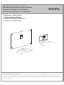
Installation and Owner’s Manual
Manual de Instrucciones y del Propietario
Manuel d’Installation et d’Utilisation
Manual de Instalação e do Proprietário
EcoPower Flush Valve
Fluxómetro EcoPower
Valve de Chasse EcoPower
Fluxômetro Self Power

TABLE OF CONTENTS
THANKS FOR CHOOSING TOTO!
Thanks for Choosing TOTO!...................................................................................................................2
Included Parts.............................................................................................................................................2
Common Tools Needed............................................................................................................................3
Initializing the Ecopower Product .............................................................................................................3
Features..................................................................................................................................3
Specifications..........................................................................................................................4
Technical Information.................................................................................................................................5
Warnings..........................................................................................
................................................6
Before Installation.......................................................................................................................................6
Installation Procedure.................................................................................................................................7
Test Run.....................................................................................................................................................14
Note to the Installer..................................................................................................................................15
Using the Flush Valve.............................................................................................................................15
Troubleshooting.................................................................................................................................16
Warranty.........................................................................................................................................20
Rough-In Dimensions...............................................................................................................................78
Reclaimed Water Specifications....... .................................................................................... ...................81
The mission of TOTO is to provide the world with healthy, hygienic and more comfortable
lifestyles. We design every product with the balance of form and function as a guiding principle.
Congratulations on your choice.
ENGLISH
2
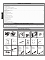
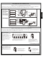
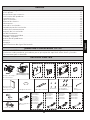
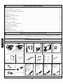
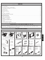
INCLUDED PARTS
Check to make sure you have all these parts from the package:
Valve body assembly
Front cover
Base frame
Hex wrench
Notice label
Installation And
Owner's Manual
(TEU2UA(R)(X) only)
Vandal proof
hex screws
Washer
Large cover Small cover Large cover Small cover
(TEU3UA(R)(X) only)
Vacuum
breaker tube
Control stop
Flush pipe
Screws
Connection cables
Small cover only
Periodic Maintenance...............................................................................................................................15
TEU3LA(X)11
TEU3UA(X)11
TEU2LA(X)21
TEU2UA(X)11
TEU3LA(X)21
TEU2LA(X)11
TET3GA32
TET3LA(X)32
TET3UA(X)32
TET2GA32
TET2LA(X)32
TET2UA(X)32
TEU3LA(X)12
TEU3UA(X)12
TEU2LA(X)12
TEU2UA(X)12
TET3GA33
TET3LA(X)33
TET3UA(X)33
TET2GA33
TET2LA(X)33
TET2UA(X)33
TET3GA31
TET3LA(X)31
TET3UA(X)31
TET2GA31
TET2LA(X)31
TET2UA(X)31
Care & Cleaning .......................................................................................................................................15

FEATURES
Fully Automatic and Hygienic
The EcoPower Flush Valve uses an infrared sensor to detect the user using and departing the
fixture, to provide an automatic flush of the fixture after a short delay. No manual operation is
required, improving the experience of use and hygiene of the fixture.
System Protection Timer
When the fixture is not used for 24 hours for toilet or 12 hours for urinal the protection
timer commands the system to flush in order to maintain the trap seal.
Manual Functionality
For maintenance and emergency use, the EcoPower Flush Valve is equipped with a manual
flushing button.
Green Features
Conserves Power
The flushing of the fixture activates a hydropower generator which generates electric power for
the next flush. (See About TOTO’s Hydropower Generator, page 5)
Conserves Water
Two functions help the EcoPower Flush Valve conserve water:
Fuzzy Logic Control
The EcoPower Flush Valve can sense how often and how long the fixture has been used to
deliver the correct amount of water. (See About Fuzzy Logic Control, page 5)
Anti Consecutive Flushing
The EcoPower Flush Valve offers water saving consecutive flush prevention. After a flush, the
valve will not automatically flush again for 10 seconds for urinals and 30 seconds for toilets.
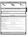
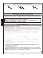
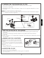
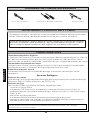
COMMON TOOLS NEEDED
TOTO EcoPower Flush Valves are designed to work for 10 years, under normal conditions,
with no minimum usage required.
Screwdrivers (Phillips and Slotted )
Adjustable wrench
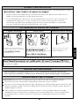
INITIALIZING THE ECOPOWER PRODUCT
ENGLISH
3
Offset pipe wrench
It will take approximately 5 minutes after connecting the battery for the electronics to initialize.
This delay is a normal part of startup.
After approximately 30 seconds, the sensor LED will start flashing in 4 second intervals until
the initialization is complete.
Thank you for choosing the latest innovation in low power consumption EcoPower products.
Please note below the duration of time required to initialize the electronics.

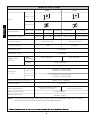
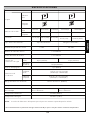
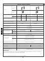
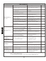
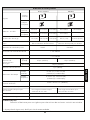
SPECIFICATIONS
32-104˚F (0-40˚C)
34-104˚F (1-40˚C)
1"NPT 3/4"NPT
1-1/4"NPSM
1-1/2"NPSM
7 psi (48kPa)
Flush Valve type Wash down flush
Automatic flushing every
24 hours of non-use
Model number
Detection time
Figure
Ambient temperature
Water temperature
Control stop inlet
Flush Valve inlet
Flush Valve outlet
Supply water
pressure
Shutoff pressure
Rated Flush Volume
Toilet/Urinal type
Trap seal protection
TET2GAR
TET3GAR
Toilet Urinal
Min
Max*
35 psi (241kPa)
(Flowing)
15psi (103kPa)
125 psi (862kPa)
1.6 G (6L)
0.5 G (1.9L)
Automatic flushing every
12 hours of non-use
0.125 G (0.47L)
6 seconds
NOTE:
Small cover
Large cover
TEU2LA(R)(X)
TEU3LA(R)(X)
TEU2UA(R)(X)
TEU3UA(R)(X)
Large cover
Small cover
12-5/8" (H) ×14-3/16"(W)
(320mm(H) ×360mm(W))
Dimension
of cover
Large cover
Small cover
4-23/32" (H) ×4-23/32"(W)
(120mm(H) ×120mm(W))
tnorf eht morf egnar noitceteD
Within 33-1/2" (850mm)
(Static)
The type of fixture determines the minimum pressure required for the valve. Consult
fixture manufacturer for the overall pressure requirement.
ENGLISH
4
TET2UA(R)(X)
TET3UA(R)(X)
1.0 G (3.8L)
TET2LA(R)(X)
TET3LA(R)(X)
1.28 G (4.8L)

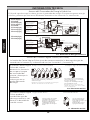
About Fuzzy Logic Control (TEU1GAR only)
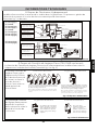
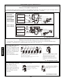
About TOTO's Hydropowered Generator
1) A turbine rotates to
generate electric
power.
3) The Automatic
Flush Valve uses the
charged power.
2) Electric power is
stored in a capacitor.
Sensor Eye
Controller
Piston
Water Supply
Flush Valve
Coil
Turbine
Cover
1)
A turbine rotates to
generate electric
power.
3)
The Automatic
Flush Valve uses the
charged power.
2)
Electric power is
stored in a capacitor.
Sensor Eye
Controller
Flush Valve
Water Supply
Cover
Turbine
Coil
TET2LA(R)(X)
TET2GAR
TET3LA(R)(X)
TET3GAR
TEU2LA(R)(X)
TEU3LA(R)(X)
TEU2UA(R)(X)
TEU3UA(R)(X)
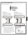
TECHNICAL INFORMATION
The flow of water causes the turbine in the power generator to rotate. This process generates
electric power and enables the automatic Flush Valve to operate. See ill. 1 below.
The Fuzzy Logic Control function automatically adjusts the discharge of water according to the
frequency and duration of usage (see ill. 2 and ill. 3).
ill. 1 Hydropowered Generator
ENGLISH
5
High Frequency of Usage Low Frequency of Usage
Less Less Less Less Less LessTypical
Long duration of usage Short Duration of Usage
Less
Typical
If the idle time is short, the system assumes frequent use
and the Flush Valve discharges less water.
Examples of high frequency use would be during a lunch
break or an intermission in a movie theatre.
A short duration of use
indicates there may be
less to flush, requiring the
Flush Valve to discharge
less flush water.
If the idle time is long, the system
assumes infrequent use, causing the
Flush Valve deliver a typical quantity of
water for thorough flushing.
Examples of low frequency use would be
during after hours at the office or a slow
day at the park.
The Fuzzy Logic
Control system judges
the frequency of
usage by the idle time
of the fixture and
causes the Flush Valve
to discharge water in
an optimal flushing
pattern.
The Fuzzy Logic Control
system predicts the
quantity of flush water
needed based on the
user's duration of use.
A long duration of use indicates
there may be more to flush,
requiring the Flush Valve to
deliver a typical quantity of flush
water for thorough flushing.
ill. 2 Frequency of Usage
ill. 3 Duration of Usage
TET2UA(R)(X)
TET3UA(R)(X)
Typical

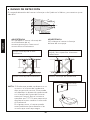
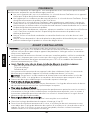
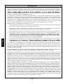
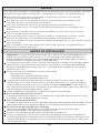
BEFORE INSTALLATION
WARNINGS
IMPORTANT: Plumbing installation must be in accordance with applicable codes and
regulations. Water supply lines must be sized to provide an adequate volume of water for
each fixture. Flush all waterlines prior to operation.
Prior to installing your Flush Valve, install the items listed below:
Bowl fixture/Urinal fixture
Drain line
Water supply line
The supply piping to these devices must be securely anchored to the building structure to
prevent the installed device moving during use. Prevent marring to the exposed surface
during installation.
IMPORTANT:
Purge all air from the supply lines before connecting
flush valve to the bowl. Trapped air in supply lines may crack the china.
Avoid damaging the surface of the infrared sensor while unpacking.
For Toilet Flush Valve:
The toilet Flush Valve may not function if toilet seat or lid cover are left upright and block the
sensor.
For Urinal Flush Valve:
The urinal Flush Valve is designed for optimal performance with a washout urinal, but a
siphon jet urinal may be substituted. Blowout urinals are not recommended.
The detection range of the infrared sensor is shown on p.19.
To prevent valve malfunction, do not install a handrail or any other object within the detection
range of the sensor. Do not install the Flush Valve where sensor faces a mirror, stainless steel
wall, other highly reflective surfaces or another infrared sensor.
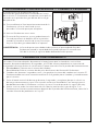
Please read and adhere to these notes. Failure to do so could result in personal injury and/or
property damage.
Never splash water on the controller. The EcoPower Flush Valve is an electric appliance.
Risk of product malfunction.
Do not strike or kick the EcoPower Flush Valve. Risk of product malfunction or water
leakage.
Do not use the EcoPower Flush Valve at temperatures exceeding what local codes or
product specification allow. Risk of product malfunction.
Do not place an item in a room with high humidity such as shower area or sauna. Risk of
product malfunction.
Never attempt to disassemble, reassemble, repair or modify the EcoPower Flush Valve
unless you are a professional. Risk of product malfunction and electric shock.
Do not use standard vacuum breaker or control stop with reclaimed water flush valve.
Do not use petroleum based products or pipe sealants, doing so could damage product
and cause water damage.
ENGLISH
6
For Reclaimed Water Flush Valve:
Only use reclaimed water angle stop and vacuum breaker.
Toilet and urinal Flush Valves are not interchangeable, check the model number on the label to
make sure you have the correct type. Toilet Flush Valve model numbers begin with ‘TET’ and
Urinal Flush Valve model numbers begin with ‘TEU’.

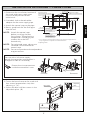
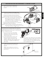
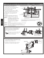
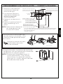
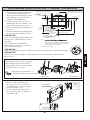
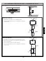
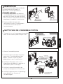
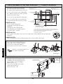
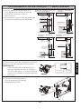
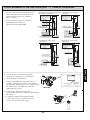
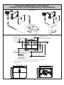
INSTALLATION PROCEDURE — LARGE COVER
NOTE:
Base frame
Adjustable
plate
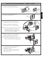
1. Determine the installation location of
the studs and water supply pipe
relative to the position of the
toilet/urinal.
3. Attach the control stop to the pipe.
4. Bore a guide hole for the flush pipe
into the wall.
Attach the control stop
NOTE:
For reclaimed water, do not use
standard vacuum breaker or
control stop.
NOTE:
Do not use petroleum based products
or pipe sealants.
before installing the box
fixing frame. Thread sealing
compounds should only be
used on the male NPT
threads only.
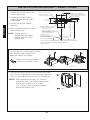
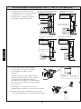
5. Fasten the base frame to the studs with
four screws (prepared on site) after
adjusting it. ( A )
6. Secure the box with four screws in the
adjustable plate. ( B )
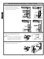
For use with a left water supply,
detach the controller and remount it
to opposite side of valve body.
Detatch Remount
Valve body
7
ENGLISH
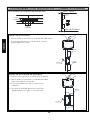
Adjustable holeAdjustable hole
Left water supply
1” NPT (toilet), 3/4” (urinal)
4-3/4” ± 1/2”
(120 ± 13mm)
Sensor location
3-7/16” (87mm)
** 11-15/16”
(303mm)
16” (406mm)
3/4” (19mm)
Stud
Toilet top spud
Ø2-3/16” (Ø56mm) hole
Urinal back spud
Ø1-5/16” (ø33mm) hole
Toilet back spud
Ø2-3/16” (ø56mm) hole
11” (279mm)
CL of sensor
* X”
** 13-1/2”
(343mm)
* 14-3/4” ‡
from top of
Urinal top spud
Ø1-1/2” (Ø38mm) hole
* X”, ‡ = At least 5” clearance from sensor to tip of toilet seat up position or
to top of grab bar is required to avoid false detection.
** Opening in wall
Right water supply
1” NPT (toilet),3/4” (urinal)
2. If needed, slide a thread solder
adapter on the water supply pipe.
inside the controller’s case.
Protect the wire connections
D
O
N
O
T
U
S
E
P
E
T
R
O
L
E
U
M
-
B
A
S
E
D
S
E
A
L
A
N
T
S
A
T
T
E
N
T
I
O
N
!

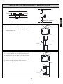
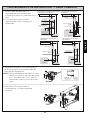
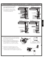
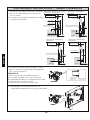
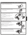
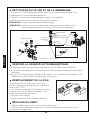
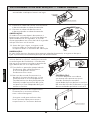
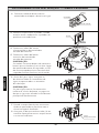
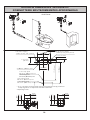
INSTALLATION PROCEDURE
— LARGE COVER
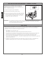
7. Pass the flush pipe and the vacuum
breaker through the guide hole (Step
3) and mount them on the bowl.
8. If required, cut the vacuum breaker
tube to the proper length.
9. Make sure that the o-ring fits in the
groove at the end of the Flush Valve
tailpiece.
NOTE: Exercise care to avoid damaging the
o-ring when inserting the tailpiece
into the control stop. If lubrication is
needed, wet the o-ring with water.
10. Connect the Flush Valve with the control
stop and vacuum breaker tube.
8
ENGLISH
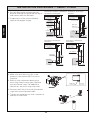
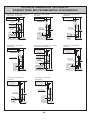
TET2LA(X)32, TET2GA32, TET2UA(X)32
TEU2LA(X)12, TEU2UA(X)12
TET2LA(X)31, TET2UA(X)31
TET2GA31
TET2LA(X)33, TET2UA(X)33,
TET2GA33
TEU2LA(X)11, TEU2LA(X)21
TEU2UA(X)11
Bowl or Urinal
Wall surface
6~6-1/2”
(152~165mm)
1-1/2” (38mm)
or 3/4” (19mm)
1-1/2”
(38mm)
5”
(127mm)
2-1/4”~2-3/4”
(57~70mm)
3-3/4”~4-7/8”
(95~124mm)
3-3/4”~4-7/8”
(95~124mm)
Top spud
Back spud
Wall mount
3”
(76mm)
Bowl
3-3/4”~4-7/8”
(95~124mm)
3-3/4”~4-7/8”
(95~124mm)
Urinal
Back spud
Floor mount
Bowl
1-1/2”
(38mm)
1-1/4” (32mm)
or 3/4” (19mm)
7” (178mm) Min space
requirement in wall
Wall surface
Wall surface
Wall surface
7” (178mm) Min space
requirement in wall
7” (178mm) Min space
requirement in wall
7” (178mm) Min space
requirement in wall

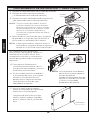
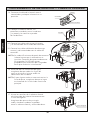
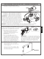
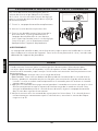
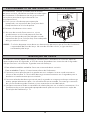
INSTALLATION PROCEDURE — LARGE COVER
Hex wrench
Control stop
NOTE:
15. To set the Flush Valve for proper
operation, open the control stop
completely and activate the Flush
Valve several times.
16. In the case of excessive flow rate
because of high water pressure,
gradually adjust the control stop
clockwise (towards the closed position)
until there is suitable water flow into
the fixture.
17. Tighten the front cover screws into
the base frame firmly with the hex
wrench.
Make sure no cord, wire or chain is
caught between the front cover and
base frame.
9
ENGLISH
The control stop should never be opened
to the point where the flow from the Flush
Valve exceeds the flow capability of the
fixture. In case of a valve failure, the water
must overflow from fixture.
The Flush Valves are preset for flush volume as
marked on the valve carton. The valve does not
require adjustment for variation in water pressure
within its operating range.
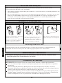
11. Connect the cables of the battery
and controller and set the battery
in place.
Connection cable
(button)
Connection cable
(sensor)
Battery
Controller
Connection cable
14. Ensure all pipe connections are completely
tightened to prevent leaking.
NOTE:
12. Connect the cables of infrared sensor
and controller with the connection
cable.
13. Connect the cables of manual button
and controller with the connection
cable.
NOTE:
It will take 5 minutes after connecting the
battery for the electronics to initialize.
After approximately 30 seconds, the
sensor LED will flash in 4 second intervals
until the initialization completes.
If for any reason it becomes necessary to
remove the control stop make sure the water
is shut off at the main supply valve.

10
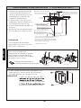
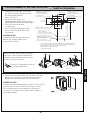
INSTALLATION PROCEDURE — SMALL COVER
NOTE:
To use with a left water supply, detach
the controller and remount it to
opposite side of valve body.
5. Secure back frame to the wall with two screws the
base frame. Other base frame installation options
with stringer and for concrete wall on next page.
Wall thickness must be 1/2" (13mm)
minimum and 1-3/8"(35mm) maximum.
If your wall thickness is less than
1/2" (13mm), please attach wooden
frame behind the wall.
1. Determine the location of the
water supply pipe.
3. Attach the control stop to
the pipe.
4. Bore a guide hole for the flush
pipe into the wall.
NOTE: Thread sealing
compounds should be
used on the male NPT
threads only.
Detatch
Remount
ENGLISH
4 x Ø5/16" (Ø8mm) hole
Left water supply pipe
1”NPT (toilet), 3/4” (urinal)
Right water supply pipe
1”NPT (toilet), 3/4” (urinal)
Toilet top spud
Ø2-3/16” (Ø56 mm) hole
Urinal back spud
Ø1-5/16” (Ø33 mm) hole
Toilet back spud
Ø2-3/16” (Ø55 mm) hole
X”
1-1/4” (31 mm)
CL of sensor
** 3-11/16”
(94mm)
11” (279mm)
16” (406mm)
** 3-11/16”
(94 mm)
* X”, ‡ = At least 5” clearance from sensor to tip of toilet seat up position or
to top of grab bar is required to avoid false detection.
** Opening in wall
4-3/4” ± 1/2”
(120 ± 13mm)
Urinal top spud
Ø1-5/16” (Ø33 mm) hole
2. If necessary, slide a sweat
solder adapter on the water
supply pipe
Protect the wire connections
inside the controller’s case.

11
INSTALLATION PROCEDURE— SMALL COVER
Option 5A (with stringer)
Max.1”(25mm)
Min.1-3/8”(35mm)
Screws
Stringer
Stringer
Tab
Stringer
Option 5B (for concrete wall)
Screws
Mortar
Tab
1. Remove all tabs on side of the base frame.
2. Fasten the base frame to stringer with 4 screws
(prepared on site).
1. Cut out a place for the cover into the wall.
2. Remove all tabs on side of the base frame
before installation.
3. Fix the base frame into place with mortar.
4. Secure the base frame with 4 screws
(prepared on site), if needed.
Other base frame installation options
ENGLISH
4-1/3”
(110mm)
4-1/3”
(110mm)
3/4”
(19mm)

12
INSTALLATION PROCEDURE — SMALL COVER
Snap ring
O-ring
8. Make sure that the o-ring fits in the
groove at the end of the Flush Valve
tailpiece.
9. Exercise care to prevent damage to
the o-ring when inserting the tailpiece
into the control stop. For additional
lubrication, wet the o-ring with water.
6. Pass the flush pipe and the vacuum
breaker through the guide hole (Step 3)
and mount them on the bowl.
7. If required, cut the vacuum breaker
tube to the proper length.
10. Connect the Flush Valve with the control
stop and vacuum breaker tube.
11. Tighten the coupling nut with a wrench to
prevent a water leak.
ENGLISH
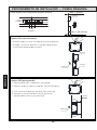
TET3LA(X)32, TET3GA32, TET3UA(X)32
TEU3LA(X)12, TEU3UA(X)12
TET3LA(X)31, TET3UA(X)31
TET3GA31
Bowl or Urinal
6~6-1/2”
(152~165mm)
1-1/2” (38mm)
or 3/4” (19mm)
1-1/2”
(38mm)
5”
(127mm)
2-1/4”~2-3/4”
(57~70mm)
3-3/4”~4-7/8”
(95~124mm)
3-3/4”~4-7/8”
(95~124mm)
Top spud
Back spud
Wall mount
3”
(76mm)
Bowl
TET3LA(X)33, TET3UA(X)33
TET3GA33
TEU3LA(X)11, TEU3LA(X)21
TEU3UA(X)11
3-3/4”~4-7/8”
(95~124mm)
Urinal
Back spud
Floor mount
Bowl
1-1/2”
(38mm)
1-1/4” (32mm)
or 3/4” (19mm)
Wall surface
Wall surface
Wall surface
Wall surface
7" (178mm) min space
in wall with a min
12" x 12" access panel
or walk-in chase
7" (178mm) min space
in wall with a min
12" x 12" access panel
or walk-in chase
7" (178mm) min space
in wall with a min
12" x 12" access panel
or walk-in chase
7" (178mm) min space
in wall with a min
12" x 12" access panel
or walk-in chase
3-3/4”~4-7/8”
(95~124mm)

13
INSTALLATION PROCEDURE — SMALL COVER
Hex wrench
Washer
Screw
12. Connect the battery cable with the
controller and set the battery in place.
13. Attach the vandal proof screws the
front cover using washers.
16. Before the supply water is turned on, be
sure all water leaks are eliminated by
tightening all the pipe connections.
If for any reason it becomes necessary to
remove the control stop, make sure the
water is shut off at the main supply valve.
17. Fasten the front cover to the base frame
by tightening the screws with the
supplied hex wrench.
18. Take care so that any cord, wire or chain
might not be caught between the front
cover and the box.
14. Connect the cables of infrared sensor
and controller with the connection
cable.
15. Connect the cables of manual button
and controller with the connection
cable.
ENGLISH
Connection cable
(button)
Connection cable
(sensor)
Battery
Controller
Connection cable
NOTE:
It will take 5 minutes after connecting the
battery for the electronics to initialize.
After approximately 30 seconds, the
sensor LED will flash in 4 second intervals
until the initialization completes.
NOTE:

14
INSTALLATION PROCEDURE — SMALL COVER
WARNING: Do not open the control stop to the point where the flow from the Flush Valve
exceeds the flow capability of the fixture. In case of a valve failure, the water
must not overflow from the fixture.
Control stop
Open
The Flush Valves are preset for flush volume as
marked on the valve carton. The valves do not
require adjustment for variation for water pressure
within its operating range.
19. Open the control stop completely.
20. Activate the Flush Valve several times.
21. In the case of excessive flow rate, adjust the flush
volume, gradually adjust the control stop clock-
wise, towards the closed position, until there is
suitable water flow into the filter.
ENGLISH
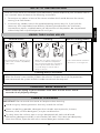
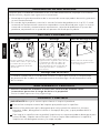
TEST RUN
1. For Toilet: Sit on the toilet seat.
For Urinal: Stand within two feet from the front of the Flush Valve.
2. Stay there for 6 seconds or more and then leave the toilet seat or the urinal. The valve
should automatically flush, immediately for urinals and after 3 seconds for toilets.
3. Press the manual flushing button. The toilet or urinal should flush and the red
light of the sensor should flash. To correct overflow from a urinal Flush Valve, adjust the
control stop clockwise.
4. Recheck all the pipe connections for water leaks. If the Flush Valve is not operating
properly following the test run consult the Troubleshooting section on p.16.
After connecting the battery, the initialization process takes 5 minutes. After approximately 30
seconds, the sensor LED will start flashing in 4 second intervals until the initialization is
complete. Please wait before starting the Test Run.

15
ENGLISH
PERIODIC MAINTENANCE
Please check the piping to your EcoPower Flush Valve at least once a month
to avoid risk of property damage.
USING THE FLUSH VALVE
Infrared Sensor Flushing
Flushing Every 12/24 hours
Manual Flushing Button
The infrared sensor detects a user
of the toilet or within 2 ft (600mm)
of the urinal.
When the user stays in place for at
least 6 seconds before departure,
the controller signals the operating
unit to trip the Flush Valve after 3
seconds delay for toilets and no
delay for urinals.
Use the manual flush switch for
maintenance or emergencies.
NOTE TO THE INSTALLER
After the Flush Valve unit has been installed correctly, please explain to your customer how to
use it and tell them to observe the following instructions:
1. Do not put any object in front of the sensor window which could obstruct the sensor,
causing it to malfunction.
2. In case of any trouble, consult the troubleshooting section on p.16. If you lack the
necessary skills required or have difficulty following the directions for installation,
maintenance, repairs, troubleshooting or adjustments of the product, do not proceed
without help from a qualified person to assist you.
When the fixture is not used for 24 hours for toilet or 12 hours for urinal the protection
timer commands the system to flush in order to maintain the trap seal.
CARE & CLEANING
IMPORTANT! Do not scratch the sensor or faceplate when cleaning.
Avoid using any cleaning materials that may scratch the surface.
Never use polishing powder, detergent that includes coarse particles, thinners,
benzene, acids, alkaline detergents, or nylon scrub brushes.
To safely clean the surface, wipe it using a dampened soft cloth with diluted
dishwashing detergent and dry it with another soft cloth. If this does not adequately
clean the surface, wipe the area with a neutral detergent and wet cloth.

16
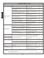
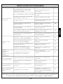
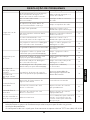
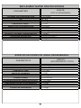
TROUBLESHOOTING
No water comes
from the flush
valve
Water does not
stop flowing
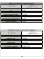
The discharge
quantity is too small
The discharge
quantity is too much
The flow rate is too
low
A red light in the
sensor window blinks
The main valve in water supply
line or the control stop is shut off
The connector is not
connected
The surface of the glass in front
of the infrared sensor is dirty
The glass is broken
There is a reflective surface in
front of the sensor
The infrared sensor or the
solenoid is out of order
The small holes in the solenoid
diaphragm are clogged
Hydropower generator clogged
The small hole in the piston is
clogged. (not for TEU*UA(R)(X))
The sealing area of the piston is
dirty. (not for TEU*UA(R)(X))
The sealing area of the solenoid
diaphragm is dirty.
The screw of the control stop or
the screw of the piston valve are
not adjusted properly
Water supply pressure is too low.
(below rated minimum pressure)
The control stop is not open enough.
The flow rate is too
high
The control stop is not adjusted
properly.
The battery is weak.
Open the main valve or the
control stop
Connect the wire
Clean the surface of the
glass
Contact distributor for
replacement
Remove the reflective
surface from the sensor
Contact distributor for
replacement
Clean the small hole in the
diaphragm and filter
Service Hydropower
Generator
Clean the small hole in the
piston
Clean the sealing area of
the piston
Clean the sealing area of
the diaphragm and filter
Adjust the discharge quantity
by the screw of the control
stop and the screw of the
piston valve
Consult with a plumbing
contractor
Adjust the control stop properly
Adjust the control stop
properly.
Check voltage with multimeter,
if below 2.6 V, contact TOTO
for replacement battery.
-
-
-
-
19
18
18
17
18
17
-
17
Piston U-packing damaged.
(not for TEU*UA(R)(X))
Inspect & replace if
necessary
18
-
18
18
18
Ref.Page
Suggested ActionPossible Cause
NOTE: Do not dismantle parts of the flush valve which are not specified in the
troubleshooting guide.
If you need further assistance, please call TOTO Tech Support at (888) 295-8134.
Problem
ENGLISH

ENGLISH
17
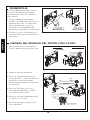
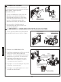
DISASSEMBLY
CLEANING PISTON ASSEMBLY
Control stop
Large cover
Small cover
Sealing Area
Small Hole
Filter
Piston U-Packing
Control stop
Supplied
hex wrench
Supplied
hex wrench
If the whole valve needs to be
removed from the water supply for
servicing, please be aware of the
cautions below:
1. Be careful not to lose or tear the
friction washer at the outlet
connection to the vacuum breaker
tube nut. To maintain a proper seal,
replace the washer if necessary.
2. Be careful when re-installing the
valve to the water supply to avoid
pinching the o-ring.
1. Turn the screw of the control stop
clockwise to turn off the water.
2. Take out the piston assembly.
3. Check the small hole in the piston to
see if it is clogged with debris, insert
a small wire to unclog hole.
4. Check the filter to see if it is
clogged with debris and gently
brush it to clean.
5. Check the sealing area of the piston
and clean it if it is dirty.
6. Check the U-Packing for cracks or
damage.

ENGLISH
18
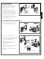
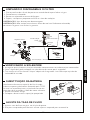
CLEANING DIAPHRAGM AND FILTER
BATTERY REPLACEMENT
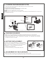
ADJUSTMENT OF THE FLOW RATE
Diaphragm
Filter
Solenoid
O-ring
Plunger
Cap
Sensor unit
TEU2UA(R)(X) and TEU3UA(R)(X)
Flow regulator
Filter
Filter
Filter
Battery
1. Turn the screw on the control stop clockwise to turn off the water.
2. Disconnect the solenoid.
3. Remove the solenoid and take out the diaphragm.
4. Check the small holes and sealing.
NOTE: See this page below for disassembly.
NOTE: Do not stretch or alter the shape of the spring in the solenoid valve in any way. It
will void the warranty.
1. Make sure that the batteries are properly placed and wires are connected.
2. With water supply turned off, place your hand in front of the sensor for 6 seconds
3. Remove and listen for a “click” sound after 3 seconds. This indicates the solenoid
plunger has been activated.
A special lithium back-up battery is used. Replace
only with the included TOTO back up battery. If a red
light in the sensor window blinks with the cycle of
4 seconds, it is time to replace the battery.
1. Remove the old battery.
2. Set the new battery at the proper position.
1. Adjust the flow rate by the turning screw on the control stop.
2. Turn the screw to the right to decrease the flow rate and turn to the left to increase.
CHECKING SOLENOID
Spring
Diaphragm
Sealing area
Small holes

19
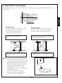
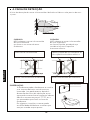
THE DETECTION RANGE
Infrared sensor
The detection range of the infrared sensor is set at the factory and does not need further
adjustment.
Another infrared sensor.
PRECAUTION
PRECAUTION
DO NOT place the infrared sensor
of one Flush Valve so that it
is in line with the sensor of
another Flush Valve sensor.
DO NOT place the infrared sensor in
front of a mirror, stainless steel wall,
or other highly reflective surface.
Infrared sensor of the automatic
Flush Valve.
Infrared sensor of the automatic
Flush Valve.
Mirror, stainless steel wall or other
highly reflective surface.
NOTE: In some cases, the valve may not
detect a user if the toilet seat is left
in an upright position. This can be
due to the rough-in dimension or
gap of the open front commercial
seat. Please lower the seat or
arrange with a TOTO or other
plumbing contractor to change the
height of the valve.
The sensor can have trouble
detecting users wearing black
clothes in some conditions.
ENGLISH
33-1/2"
(850mm)
15°
Max 19-11/16”
(Max 500mm)

20
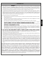
WARRANTY
1. TOTO warrants its electronic flush valves, faucets and soap dispensers (“Product”) to be free from defects in
materials and workmanship during normal use when properly installed and serviced, for a period of three (3) years
from date of purchase. This limited warranty is extended only to the ORIGINAL PURCHASER of the Product and is
not transferable to any third party, including but not limited to any subsequent purchaser or owner of the Product.
This warranty applies only to TOTO Product purchased and installed in North, Central and South America.
2. TOTO’s obligations under this warranty are limited to repair, replacement or other appropriate adjustment, at
TOTO’s option, of the Product or parts found to be defective in normal use, provided that such Product was properly
snoitcepsni hcus ekam ot thgir eht sevreser OTOT .snoitcurtsni htiw ecnadrocca ni decivres dna desu ,dellatsni
ni strap ro robal rof egrahc ton lliw OTOT .tcefed eht fo esuac eht enimreted ot redro ni yrassecen eb yam
connection with warranty repairs or replacements. TOTO is not responsible for the cost of removal, return and/or
reinstallation of the Product.
5. THIS WARRANTY GIVES YOU SPECIFIC LEGAL RIGHTS. YOU MAY HAVE OTHER RIGHTS WHICH VARY
FROM STATE TO STATE, PROVINCE TO PROVINCE OR COUNTRY TO COUNTRY.
6. To obtain warranty repair service under this warranty, you must take the Product or deliver it prepaid to a TOTO
service facility together with proof of purchase (original sales receipt) and a letter stating the problem, or contact
a TOTO distributor or products service contractor, or write directly to TOTO U.S.A., INC., 1155 Southern Road,
Morrow, GA 30260 (888) 295 8134 or (678) 466-1300, if outside the U.S.A. If, because of the size of the Product
or nature of the defect, the Product cannot be returned to TOTO, receipt by TOTO of written notice of the defect
esoohc yam OTOT ,esac hcus nI .yreviled etutitsnoc llahs )tpiecer selas lanigiro( esahcrup fo foorp htiw rehtegot
to repair the Product at the purchaser’s location or pay to transport the Product to a service facility.
THIS WRITTEN WARRANTY IS THE ONLY WARRANTY MADE BY TOTO. REPAIR, REPLACEMENT OR OTHER APPROPRIATE
ADJUSTMENT AS PROVIDED UNDER THIS WARRANTY SHALL BE THE EXCLUSIVE REMEDY AVAILABLE TO THE ORIGINAL
PURCHASER. TOTO SHALL NOT BE RESPONSIBLE FOR LOSS OF THE PRODUCT OR FOR OTHER INCIDENTAL, SPECIAL
OR CONSEQUENTIAL DAMAGES OR EXPENSES INCURRED BY THE ORIGINAL PURCHASER, OR FOR LABOR OR OTHER
COSTS DUE TO INSTALLATION OR REMOVAL, OR COSTS OF REPAIRS BY OTHERS, OR FOR ANY OTHER EXPENSE NOT
SPECIFICALLY STATED ABOVE. IN NO EVENT WILL TOTO’S RESPONSIBI
LITY EXCEED THE PURCHASE PRICE OF THE
PRODUCT. EXCEPT TO THE EXTENT PROHIBITED BY APPLICABLE LAW, ANY IMPLIED WARRANTIES, INCLUDING THAT
OF MERCHANTABILITY OR FITNESS FOR USE OR FOR A PARTICULAR PURPOSE, ARE EXPRESSLY DISCLAIMED. SOME
STATES DO NOT ALLOW LIMITATIONS ON HOW LONG AN IMPLIED WARRANTY LASTS, OR THE EXCLUSION OR
LIMITATION OF INCIDENTAL OR CONSEQUENTIAL DAMAGES, SO THE ABOVE LIMITATION AND EXCLUSION MAY NOT
APPLY TO YOU.
3. This warranty does not apply to the following items:
a. Damage or loss sustained in a natural calamity such as fire, earthquake, flood, thunder, electrical storm, etc.
b. Damage or loss resulting from any accident, unreasonable use, misuse, abuse, negligence, or improper
care, cleaning, or maintenance of the Product.
c. Damage or loss resulting from sediments or foreign matter contained in a liquid soap system.
ro/dna hsrah a ni tcudorP eht fo noitallatsni morf ro noitallatsni reporpmi morf gnitluser ssol ro egamaD .d
hazardous environment, or improper removal, repair or modification of the Product.
e. Damage or loss resulting from electrical surges or lightning strikes or other acts which are not the fault of
TOTO or which the Product is not specified to tolerate.
f. Damage or loss resulting from normal and customary wear and tear, such as gloss reduction, scratching or
fading over time due to use, cleaning practices or water or atmospheric conditions, including but not limited
to, the use of bleach, alkali, acid cleaners, dry (powder) cleaners or any other abrasive cleaners or the use
of metal or nylon scrubbers.
ENGLISH
4. In order for this limited warranty to be valid, proof of purchase is required. TOTO encourages warranty registration
upon purchase to create a record of Product ownership at http://www.totousa.com is required. TOTO encourages
registration upon purchase and failure to register will not diminish you r limited warranty rights.
A página está carregando ...
A página está carregando ...
A página está carregando ...
A página está carregando ...
A página está carregando ...
A página está carregando ...
A página está carregando ...
A página está carregando ...
A página está carregando ...
A página está carregando ...
A página está carregando ...
A página está carregando ...
A página está carregando ...
A página está carregando ...
A página está carregando ...
A página está carregando ...
A página está carregando ...
A página está carregando ...
A página está carregando ...
A página está carregando ...
A página está carregando ...
A página está carregando ...
A página está carregando ...
A página está carregando ...
A página está carregando ...
A página está carregando ...
A página está carregando ...
A página está carregando ...
A página está carregando ...
A página está carregando ...
A página está carregando ...
A página está carregando ...
A página está carregando ...
A página está carregando ...
A página está carregando ...
A página está carregando ...
A página está carregando ...
A página está carregando ...
A página está carregando ...
A página está carregando ...
A página está carregando ...
A página está carregando ...
A página está carregando ...
A página está carregando ...
A página está carregando ...
A página está carregando ...
A página está carregando ...
A página está carregando ...
A página está carregando ...
A página está carregando ...
A página está carregando ...
A página está carregando ...
A página está carregando ...
A página está carregando ...
A página está carregando ...
A página está carregando ...
A página está carregando ...
A página está carregando ...
A página está carregando ...
A página está carregando ...
A página está carregando ...
A página está carregando ...
A página está carregando ...
A página está carregando ...
-
 1
1
-
 2
2
-
 3
3
-
 4
4
-
 5
5
-
 6
6
-
 7
7
-
 8
8
-
 9
9
-
 10
10
-
 11
11
-
 12
12
-
 13
13
-
 14
14
-
 15
15
-
 16
16
-
 17
17
-
 18
18
-
 19
19
-
 20
20
-
 21
21
-
 22
22
-
 23
23
-
 24
24
-
 25
25
-
 26
26
-
 27
27
-
 28
28
-
 29
29
-
 30
30
-
 31
31
-
 32
32
-
 33
33
-
 34
34
-
 35
35
-
 36
36
-
 37
37
-
 38
38
-
 39
39
-
 40
40
-
 41
41
-
 42
42
-
 43
43
-
 44
44
-
 45
45
-
 46
46
-
 47
47
-
 48
48
-
 49
49
-
 50
50
-
 51
51
-
 52
52
-
 53
53
-
 54
54
-
 55
55
-
 56
56
-
 57
57
-
 58
58
-
 59
59
-
 60
60
-
 61
61
-
 62
62
-
 63
63
-
 64
64
-
 65
65
-
 66
66
-
 67
67
-
 68
68
-
 69
69
-
 70
70
-
 71
71
-
 72
72
-
 73
73
-
 74
74
-
 75
75
-
 76
76
-
 77
77
-
 78
78
-
 79
79
-
 80
80
-
 81
81
-
 82
82
-
 83
83
-
 84
84


em outros idiomas
- español: Toto SS Manual de usuario
- français: Toto SS Manuel utilisateur
Artigos relacionados
-
Toto TEU1GA12-CP Guia de instalação
-
-
Toto 0GU219 Guia de instalação
-
Toto 0GU220 Guia de instalação
-
-
Toto WT172M Guia de instalação
-
-
Toto TOTCT447CFG01 Guia de instalação
-
-
Outros documentos
-
Maxim Lighting 18205WADBZ Quarry 2-Light LED Pendant Guia de instalação
-
American Standard 6516001EC.020 Guia de instalação
-
American Standard 6590001EC.020 Guia de instalação
-
GROHE 42227000 Guia de instalação
-
Kohler 10668-SV-CP Guia de instalação
-
Dometic MasterFlush7640 Instruções de operação
-
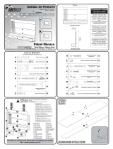 Artely Monaco Manual do usuário
-
Delabie TEMPOSTOP time flow urinal valve Guia de instalação
-
Honeywell D06FH Manual do proprietário
-
Elkay EZSTL8LC Guia de instalação
