A página está carregando...

1
30/03/2017
3.300.154/A
Parti di ricambio e schema elettrico
Spare parts and electrical schematic
Ersatzteile und Schaltplan
Pièces détachées et schéma électrique
Partes de repuesto y esquema eléctrico
Partes sobressalentes e esquema eléctrico
Varaosat ja sähkökaavio
Reservedele og elskema
Reserveonderdelen en elektrisch schema
Reservdelar och elschema
Antallaktika v kai hlektriko v sce-
d ia vgr amma
Pagg. Sid. sel.: 85 ÷ 89
I -MANUALE DI ISTRUZIONI PER SALDATRICE A FILO pag. 2
GB -INSTRUCTION MANUAL FOR WIRE WELDING MACHINE page 10
D -BETRIEBSANLEITUNG FÜR DRAHTSCHWEISSMASCHINE seite 17
F -MANUEL D’INSTRUCTIONS POUR POSTE A SOUDER A FIL page 25
E -MANUAL DE INSTRUCCIONES PARA SOLDADORA DE HILO pag. 33
P -MANUAL DE INSTRUÇÕES PARA MÁQUINA DE SOLDAR A FIO pag. 41
SF -KÄYTTÖOPAS MIG-HITSAUSKONEELLE sivu. 48
DK -INSTRUKTIONSMANUAL FOR SVEJSEAPPARAT TIL TRÅDSVEJSNING side.55
NL -GEBRUIKSAANWIJZING VOOR MIG-LASMACHINE pag.62
S -INSTRUKTIONSMANUAL FÖR TRÅDSVETS sid.70
GR -
ODHGOS CRHSEWS GIA SUSKEUHV SUGKOLLHSHS ME NHMA sel.77

2
MANUALE DI ISTRUZIONI PER SALDATRICI A FILO
IMPORTANTE: PRIMA DELLA MESSA IN OPERA DEL-
L’APPARECCHIO LEGGERE IL CONTENUTO DI QUESTO
MANUALE E CONSERVARLO, PER TUTTA LA VITA OPE-
RATIVA, IN UN LUOGO NOTO AGLI INTERESSATI.
QUESTO APPARECCHIO DEVE ESSERE UTILIZZATO
ESCLUSIVAMENTE PER OPERAZIONI DI SALDATURA.
1 PRECAUZIONI DI SICUREZZA
LA SALDATURA ED IL TAGLIO AD ARCO POS-
SONO ESSERE NOCIVI PER VOI E PER GLI
ALTRI, pertanto l’utilizzatore deve essere istruito contro i
rischi, di seguito riassunti, derivanti dalle operazioni di
saldatura. Per informazioni più dettagliate richiedere il
manuale cod.3.300758
RUMORE.
Questo apparecchio non produce di per se rumo-
ri eccedenti gli 80dB. Il procedimento di taglio
plasma/saldatura può produrre livelli di rumore
superiori a tale limite; pertanto, gli utilizzatori dovranno
mettere in atto le precauzioni previste dalla legge.
CAMPI ELETTROMAGNETICI- Possono essere dannosi.
· La corrente elettrica che attraversa qualsi-
asi conduttore produce dei campi elettro-
magnetici (EMF). La corrente di saldatura o
di taglio genera campi elettromagnetici at-
torno ai cavi e ai generatori.
· I campi magnetici derivanti da correnti elevate possono
incidere sul funzionamento di pacemaker. I portatori di
apparecchiature elettroniche vitali (pacemaker) devono
consultare il medico prima di avvicinarsi alle operazioni
di saldatura ad arco, di taglio, scriccatura o di saldatura
a punti.
· L’ esposizione ai campi elettromagnetici della saldatura
o del taglio potrebbe avere effetti sconosciuti sulla salute.
Ogni operatore, per ridurre i rischi derivanti dall’ esposi-
zione ai campi elettromagnetici, deve attenersi alle se-
guenti procedure:
- Fare in modo che il cavo di massa e della pinza por-
taelettrodoodellatorciarimanganoafancati.Se
possibile,ssarliassiemecondelnastro.
- Non avvolgere i cavi di massa e della pinza porta
elettrodo o della torcia attorno al corpo.
- Non stare mai tra il cavo di massa e quello della
pinza portaelettrodo o della torcia. Se il cavo di
massa si trova sulla destra dell’operatore anche
quello della pinza portaelettrodo o della torcia deve
stare da quella parte.
- Collegare il cavo di massa al pezzo in lavorazione
più vicino possibile alla zona di saldatura o di taglio.
- Non lavorare vicino al generatore.
ESPLOSIONI.
· Non saldare in prossimità di recipienti a pressio-
ne o in presenza di polveri, gas o vapori esplosivi.
· Maneggiare con cura le bombole ed i regolatori
di pressione utilizzati nelle operazioni di saldatura.
COMPATIBILITÀ ELETTROMAGNETICA
Questo apparecchio è costruito in conformità alle indicazioni
contenute nella norma IEC 60974-10(Cl. A) e deve essere
usato solo a scopo professionale in un ambiente indu-
striale. Vi possono essere, infatti, potenziali difcoltà
nell’assicurare la compatibilità elettromagnetica in un
ambiente diverso da quello industriale.
ALTA FREQUENZA
• L'alta frequenza (H.F.) puo' interferire
con la radio navigazione, i servizi di sicu-
rezza, i computers, e in generale con le
apparecchiature di comunicazione
• Far eseguire l’ installazione solo da per-
sonequalicatechehannofamiliaritàcon
le apparecchiature elettroniche.
•L'utilizzatorenalehalaresponsabilitàdiavvalersidiun
elettricistaqualicatochepossaprontamenteprovvede-
re a qualsiasi problema di interferenza risultante dall'in-
stallazione
•Incasodinoticadall’enteFCCperinterferenze,smet-
tere immediatamente di usare l’apparecchiatura
• L'apparecchio deve essere regolarmente mantenuto e
controllato
• Il generatore di alta frequenza deve rimanere chiuso,
mantenere alla giusta distanza gli elettrodi dello spinte-
rometro.
SMALTIMENTO APPARECCHIATURE ELETTRI-
CHE ED ELETTRONICHE.
Non smaltire le apparecchiature elettriche assie-
meairiutinormali!
In ottemperanza alla Direttiva Europea 2002/96/CE sui
riutidaapparecchiatureelettricheedelettronicheere-
lativa attuazione nell’ambito della legislazione nazionale,
leapparecchiature elettrichegiunteanevita devono
essere raccolte separatamente e conferite ad un impian-
to di riciclo ecocompatibile. In qualità di proprietario delle
apparecchiature dovrà informarsi presso il nostro rappre-
sentante in loco sui sistemi di raccolta approvati. Dando
applicazione a questa Direttiva Europea migliorerà la si-
tuazioneambientaleelasaluteumana!
IN CASO DI CATTIVO FUNZIONAMENTO RICHIEDETE
L’ASSISTENZA DI PERSONALE QUALIFICATO.
1.1 TARGA DELLE AVVERTENZE
Il testo numerato seguente corrisponde alle caselle nu-
merate della targa.
B.Irullinitrainalopossonoferirelemani.
C.Il lo di saldatura ed ilgruppo trainalo sono sotto
tensione durante la saldatura. Tenere mani e oggetti
metallici a distanza.
1. Le scosse elettriche provocate dall’elettrodo di sal-
datura o dal cavo possono essere letali. Proteggersi
adeguatamente dal pericolo di scosse elettriche.
1.1 Indossare guanti isolanti. Non toccare l’elettrodo a
mani nude. Non indossare guanti umidi o danneggiati.
1.2 Isolarsi dal pezzo da saldare e dal suolo.

3
1.3 Scollegare la spina del cavo di alimentazione prima di
lavorare sulla macchina.
2. Inalare le esalazioni prodotte dalla saldatura può es-
sere nocivo alla salute.
2.1 Tenere la testa lontana dalle esalazioni.
2.2 Utilizzare un impianto di ventilazione forzata o di sca-
rico locale per eliminare le esalazioni.
2.3 Utilizzare una ventola di aspirazione per eliminare le
esalazioni.
3. Le scintille provocate dalla saldatura possono causa-
re esplosioni o incendi.
3.1Tenereimaterialiinammabililontanodall’areadisal-
datura.
3.2 Le scintille provocate dalla saldatura possono causare
incendi. Tenere un estintore nelle immediate vicinanze
e far sì che una persona resti pronta ad utilizzarlo.
3.3 Non saldare mai contenitori chiusi.
4. I raggi dell’arco possono bruciare gli occhi e ustiona-
re la pelle.
4.1 Indossare elmetto e occhiali di sicurezza. Utilizzare
adeguate protezioni per le orecchie e camici con il
colletto abbottonato. Utilizzare maschere a casco
conltridellacorrettagradazione.Indossareunapro-
tezione completa per il corpo.
5. Leggere le istruzioni prima di utilizzare la macchina
od eseguire qualsiasi operazione su di essa.
6. Non rimuovere né coprire le etichette di avvertenza
2 DESCRIZIONI GENERALI
La saldatrice è un impianto idoneo alla saldatura MIG/
MAG sinergico e MIG/MAG pulsato sinergico, realizzato
con tecnologia inverter ed è equipaggiato con un
motoriduttore a 2 rulli.
Questa saldatrice non deve essere usata per sgelare tubi.
2.1 SPIEGAZIONE DEI DATI TECNICI
L’ apparecchio è costruito secondo le seguenti norme:
IEC 60974-1 / IEC 60974-10 (CL. A) / IEC 61000-3-11 / IEC
61000-3-12.
N°. Numero di matricola da citare per ogni
richiesta relativa alla saldatrice.
Convertitore statico di frequenza monofase
trasformatore raddrizzatore.
MIG Adatto per saldatura MIG-MAG.
U0. Tensione a vuoto secondaria.
X. Fattore di servizio percentuale. Il fattore di
servizio esprime la percentuale di 10 minuti in
cui la saldatrice può lavorare ad una determi-
nata corrente senza surri-scaldarsi.
I2. Corrente di saldatura
U2. Tensione secondaria con corrente I2
U1. Tensione nominale di alimentazione.
1~ 50/60Hz Alimentazione monofase 50 oppure 60 Hz.
I1 Max Corrente max. assorbita alla corrispondente
corrente I2 e tensione U2.
I1 eff E’ il massimo valore della corrente effettiva
assorbita considerando il fattore di servizio.
Solitamente, questo valore corrisponde alla
portata del fusibile (di tipo ritardato) da utiliz-
zare come protezione per l’ apparecchio.
IP23S Grado di protezione della carcassa.
Grado 3 come seconda cifra signica che
questo apparecchio può essere immagazzi-
nato, ma non impiegato all’esterno durante
le precipitazioni, se non in condizione protetta.
S
Idonea a lavorare in ambienti con rischio
accresciuto.
NOTE: L’apparecchio è inoltre stato progettato per lavorare
in ambienti con grado di inquinamento 3. (Vedi IEC 60664).
2.3 PROTEZIONI
2.3.1 PROTEZIONE DI BLOCCO
In caso di malfunzionamento della saldatrice, sul display
A può comparire una scritta di WARNINGcheidenticail
tipo di difetto, se spegnendo e riaccendendo la macchina
la scritta rimane contattare il servizio assistenza.
2.3.2 Protezione termica
Quest’apparecchio è protetto da un termostato il qua-
le, se si superano le temperature ammesse, impedisce
il funzionamento della macchina. In queste condizioni il
ventilatore continua a funzionare ed il display A visualiz-
za, in modo lampeggiante, la sigla WARNING tH.

4
3 COMANDI POSTI SUL PANNELLO ANTERIORE.
Art.
305
INVERTER
®
POCKET
PULSE
POCKET
PULSE
MIG 1820/M synergic
C
D
B
A
A - DISPLAY.
Visualizza sia i parametri di saldatura che tutte le funzioni
di saldatura.
B - MANOPOLA
Seleziona e regola sia le funzioni che i parametri di sal-
datura.
C - ATTACCO CENTRALIZZATO
A cui va collegata la torcia di saldatura.
D – CAVO MASSA
4 COMANDI POSTI SUL PANNELLO POSTERIORE.
E
G F
E – RACCORDO CON TUBO GAS.
F – INTERRUTTORE.
Accende e spegne la macchina
G – CAVO RETE.
5 MESSA IN OPERA E INSTALLAZIONE PER
SALDATURA MIG CON GAS
Posizionare la saldatrice in modo da consentire una libera
circolazione d'aria al suo interno ed evitare il più possibile
che entrino polveri metalliche o di qualsiasi altro genere.
• L'installazione della macchina deve essere fatta da perso-
nalequalicato.
• Tutti i collegamenti devono essere eseguiti in conformità
delle vigenti norme (IEC/CEI EN 60974-9) e nel pieno ri-
spetto della legge antinfortunistica.
•Vericare chelatensione d'alimentazione corrisponda a
quella nominale della saldatrice.
• Dimensionare i fusibili di protezione in base ai dati riportati
sulla targa dei dati tecnici.
Assicurarsi che il cavo massa D, all’interno del vano
bobina, sia collegato al polo negativo uscente dalla
paratia.
A anco ai 2 morsetti e stampata in rilievo la polarità,
il polo positivo + è quello più in alto, il più vicino al
motore trainalo, il polo – è quello più in basso, il più
vicino all’uscita del cavo massa.
Collegare il morsetto del cavo massa D al pezzo da saldare.
Aprire lo sportello laterale. Montare la bobina del lo se-
guendo le istruzioni sotto riportate.

5
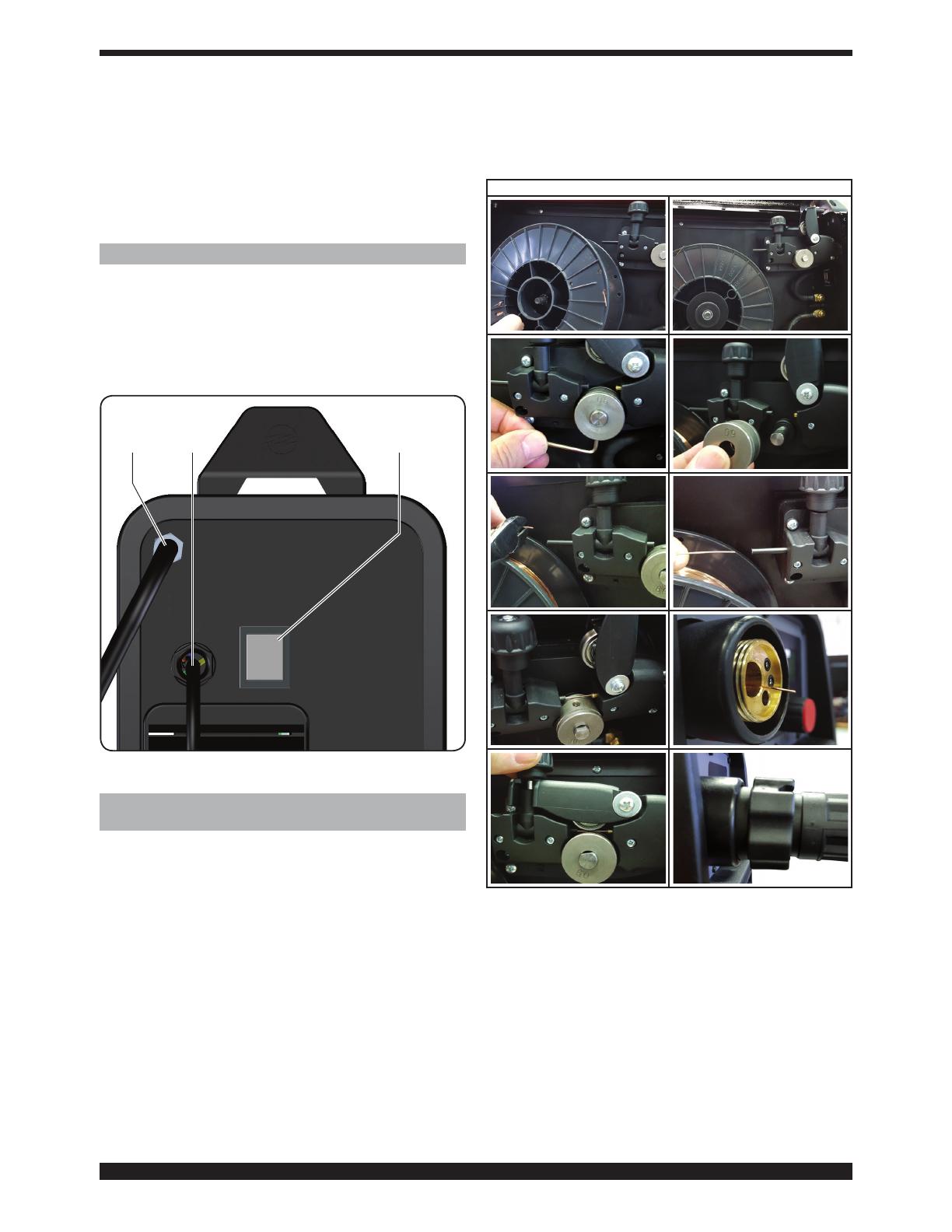
SEQUENZA MONTAGGIO BOBINA
fig.1
fig.2
fig.3 fig.4
fig.5 fig.6
fig.7 fig.8
fig.9
fig.10
NB. Durante la sequenza di montaggio la saldatrice deve
rimanere spenta per evitare che il rullo del motore in mo-
vimento possa creare pericolo per l’operatore.
• Inserire la bobina sul supporto all’interno del vano
comemostratoing.1.
• La bobina deve essere montata sul supporto in modo
cheillosisvolgainsensoorario.Eimportanteche
illosiafermatosullabobinadallatoavistavedig.
2. Bloccare la bobina sul supporto, come mostrato in
gura.
• Controllare che il rullo di traino sia posizionato corret-
tamenteinbasealdiametroealtipodiloutilizzato.
Per smontare il rullo, allineare la parte piatta del perno
porta rullo in basso, in modo che la chiave possa es-
sereinseritaall’internodellavitedissaggio,svitarela
vite,slareilrullo,rimontareilrulloinmodochelagola
corrispondaalloutilizzatovedigg.3e4.
• Tagliareilloconunutensilebenaflato,mantenendo
illotraleditainmodochenonpossasrotolarsi,in-
larlo all’interno del tubetto plastico uscente dal moto-
riduttoreeaiutandosiconunditoinlarloancheall’in-
ternodellacannettainacciaio,noafarlofuoriuscire
dall’adattatoreinottonevedigg.5-6-7-8.
• Chiudere il braccetto di traino, facendo attenzione al
lo,deveessereallineatoconlagoladelrullo,vedig.9.
• Montare la torcia di saldatura.
Dopo aver montato la bobina e la torcia, accendere la
macchina,scegliere la curva sinergica adeguata, seguen-
do le istruzioni descritte nel paragrafo “ funzioni di servi-
zio (PROCESS PARAMS). Togliere l’ugello gas e svitare
l’ugello portacorrente dalla torcia. Premere il pulsante
della torcia no alla fuoriuscita del lo, ATTENZIONE
tenere il viso lontano dalla lancia terminale mentre
il lo fuoriesce,avvitarel’ugelloportacorrenteeinlare
l’ugello gas.
Aprireilriduttoredellabombolaeregolareilussodel
gas a 8 – 10 l/min.
Durante la saldatura il display A visualizza la corrente e
la tensione effettiva di lavoro, i valori visualizzati possono
essere leggermente diversi dai valori impostati, questo
può dipendere da molteplici fattori, tipo di torcia, spes-
sore diverso dal nominale, distanza tra ugello porta cor-
rente e il materiale che si sta saldando e la velocità di
saldatura. I valori dicorrentee tensione,alla nedella
saldatura rimangono memorizzati sul display A, per vi-
sualizzare i valori impostati è necessario muovere leg-
germente la manopola B, mentre spingendo il pulsante
torcia senza saldare, sul display A compare il valore di
tensione a vuoto e il valore di corrente uguale a 0.
6 MESSA IN OPERA E INSTALLAZIONE PER SALDA-
TURA SENZA GAS.
Le azioni per preparare la macchina alla saldatura sono le
stesse di quelle descritte precedentemente ma per que-
sto tipo di saldatura agire come segue:
Montareunabobinadiloanimatopersaldaturasenza
gas selezionando la curva sinergica adeguata (E71TGS
0,9mm), seguendo le istruzioni descritte nel paragrafo “
funzioni di servizio (PROCESS PARAMS).
Montare una torcia adeguata al lo animato, dato che
questolo.nonavendounaprotezionegassosariscalda
molto di più la lancia terminale.
Montareilrullotrainaloadattoalloanimatodiametro
0,9mm e l’ugello portacorrente sulla torcia di saldatura.
Collegare il terminale del cavo massa, posto all’inter-
no del vano bobina, al polo positivo mentre il termi-
nale del cavo che fuoriesce dalla paratia deve essere
collegato al polo negativo.
Collegare il morsetto del cavo di massa al pezzo da
saldare.

6
7 DESCRIZIONE FUNZIONI VISUALIZZATE SUL
DISPLAY A.
Machine 305
Version 001
Build Mar 23 2016
Table 001
Information
All’accensione della macchina
il display A per qualche istante
visualizza: il numero di artico-
lo della macchina, la versione,
la data di sviluppo del softwa-
re, e il numero di release delle
curve sinergiche (questa informazione viene riportata anche
all'interno del capitolo 7.1 FUNZIONI DI SERVIZIO).
Subito dopo l’accensione il display A visualizza:
La curva sinergica utilizzata, il modo di saldatura 2T, 4T o
3L, la funzione SPOT se attivata, il processo di saldatura
"SHORT o PULSATO", la corrente di saldatura, la velo-
citàinmetrialminutodellodisaldatura,latensionedi
saldatura e lo spessore consigliato.
Per aumentare o diminuire i parametri di saldatura è suf-
cienteregolaretramitelamanopolaB, i valori cambiano
tutti assieme, in modo sinergico.
PermodicarelatensionedisaldaturaVèsufcientepre-
mere per meno di 2 secondi la manopola B, sul display
compare (Arc Length o lunghezza d’arco) una barra di
regolazioneconlo0centrale,ilvalorepuòesseremodi-
cato tramite la manopola B da -9,9 a 9,9 per uscire dalla
funzione premere brevemente la manopola B.
Modicandoilvalore,unavoltauscitidalsottomenù,di
ancoallatensioneV, comparirà una freccia che se rivol-
ta verso l’alto indicherà una correzione maggiore del va-
lore preimpostato mentre la freccia rivolta verso il basso
indicherà una correzione minore.
Fe 0.8mm Ar 18 2CO
2T
5.7m/m
100A
1.4mm16.8 V
MIG
Arc Length
MIN
MAX
0.0V
Fe 0.8mm Ar 18 2CO
2T
7.0m/m
100A
2.4mm21.9 V
MIG
Arc Length
MIN
MAX
0.0V
7.1 FUNZIONI DI SERVIZIO (PROCESS PARAMS)
VISUALIZZATE SUL DISPLAY A.
Per accedere a queste funzioni bisogna partire dalla
schermata principale e premere per almeno 2 secondi la
manopola B.
Perentraredentrolafunzioneèsufcienteselezionarla
con la manopola B e premere la stessa per meno di 2
secondi. Per ritornare alla schermata principale premere
per almeno 2 secondi la manopola B.
Le funzioni selezionabili sono:
• Curva sinergica (Wire Selection).
Per scegliere la curva sinergica, è necessario, tramite
la manopola B, selezionare e premere sulla curva pro-
posta dal display A,èsufcienteselezionarelacurva
che ci interessa e confermare la scelta premendo per
meno di 2 secondi sulla manopola B.
Dopo aver premuto la manopola B si ritorna alla scher-
mata precedente (PROCESS PARAMS).
Fe 0.8mm Ar 18 2CO
Process SHORT
Start Mode 2T
Spot OFF
Process Params
Fe 0.8mm Ar 18 2CO
Fe 0.8mm 2CO
Fe 0.9mm Ar 18 2CO
Fe 0.9mm 2CO
Wire selection
• Process
Fe 0.8mm Ar 18 2CO
Process SHORT
Start Mode 2T
Spot OFF
Process Params
SHORT
PULSED
Process
Per scegliere o confermare il tipo di saldatura, è ne-
cessario, tramite la manopola B, selezionare e preme-
re, per almeno 2 secondi su Short o Pulsed.
Shortidenticacheiltipodisaldaturasceltoèshort
sinergico.
Pulsedidenticacheiltipodisaldaturasceltoèpulsa-
to sinergico.
• Modo di saldatura (Start Mode).
Per scegliere il modo di inizio saldatura 2T, 4T o 3L se-
lezionare tramite la manopola B uno dei 2 modi e pre-
mere la manopola B per meno di 2 secondi per con-
fermare la scelta, questa operazione ci riporta sempre
alla schermata precedente (PROCESS PARAMS).
Modo 2T, la macchina inizia a saldare quando si pre-
me il pulsante della torcia e si interrompe quando lo si
rilascia.
Modo 4T, per iniziare la saldatura premere e rilasciare
il pulsante torcia, per terminare la saldatura premere e
rilasciare nuovamente.
Fe 0.8mm Ar 18 2CO
Process SHORT
Start Mode 2T
Spot OFF
Process Params
2T
4T
3L
Start Mode
Modo 3L, particolarmente consigliato per la saldatura
dell’alluminio.
Tramite il pulsante della torcia sono disponibili 3 cor-
renti richiamabili in saldatura. L’impostazione delle
correnti e del tempo di slope è la seguente:
Start Curr corrente di partenza, possibilità di regola-
zione dal 10 al 200% della corrente impostata di salda-
tura.
Slope time, possibilità di regolazione da 0,1 a 10 se-
condi.Denisceiltempodiraccordotralacorrentedi
partenza (Start Curr) e la corrente di saldatura e tra la
correntedisaldaturaelacorrentedicraterllerori-
empimentodelcrateredinesaldatura(Crater Curr).

7
Start Mode 2T
Spot ON
Spot Time 1.0s
Pause Time OFF
Process Params
Pause Time
OFF
5.0s
0.0s
• HSA (hot start automatico).
Questa funzione è inibita quando la funzione 3L è at-
tiva. Una volta attivata la funzione, l’operatore potrà
regolare la corrente di partenza (Start Curr) dal 10 al
200% della corrente di saldatura (Default 130%). Po-
trà regolare la durata di questa corrente (S.C. Time)
da 0,1 a 10 secondi (Default 0,5 sec.). Potrà regolare
anche il tempo di passaggio (Slope Time) tra la cor-
rente di partenza (Start Curr) e la corrente di saldatu-
ra da 0,1 a 10 secondi (Default 0,5 sec.).
HSA ON
Start Curr. 135%
0,5sS.C. Time
Slope Time 0,5s
Process Params
Start Curr
10
200
135%
S.C Time
0.5s
0.1s
10.0s
Slope Time
0.5s
0.1s
10.0s
• CRA (crater ller- riempimento del cratere nale).
Questa funzione è inibita quando la funzione 3L è at-
tiva. Funziona in saldatura 2T, 4T e anche in abbina-
mento con la funzione HSA.
Dopo aver attivato la funzione, l’operatore potrà rego-
lare il tempo di raccordo (Slope Time) tra la corrente
di saldatura e la corrente di riempimento del cratere
(Crater Curr.) da 0,1 a 10 secondi (Default 0,5 sec.).
Potrà regolare la corrente di riempimento del cratere
(Crater Curr.) dal 10 al 200% della corrente di salda-
tura (Default 60%).
Potrà regolare il tempo (C.C. Time) della durata del-
la corrente di riempimento del cratere da 0,1 a 10
secondi Default 0,5 sec.).
CRA ON
Slope Time 0,5s
Crater Current 60%
C.C. Time 0,5s
Process Params
Slope Time
0.5s
0.1s
10.0s
Crater Curr
10
200
60%
C.C. Time
0.5s
0.1s
10.0s
Possibilità di regolazione da dal 10 al 200% della cor-
rente impostata di saldatura.
La saldatura inizia alla pressione del pulsante torcia.
La corrente richiamata sarà la corrente di partenza
Start Curr. Questa corrente viene mantenuta no a
quando il pulsante torcia rimane premuto; al rilascio
del pulsante, la corrente di partenza si raccorda alla
correntedisaldaturaequestavienemantenutanoa
quando il pulsante torcia non viene nuovamente pre-
muto. Alla successiva pressione del pulsante torcia la
corrente di saldatura si raccorda alla corrente di cra-
ter-ller(Crater-Curr)edèmantenutanoalrilascio
del pulsante torcia.
Start Mode 3L
Start Curr 135%
Slope Time 0,55
Crater Curr 60%
Process Params
Start Curr
10
200
135%
Slope Time
0.5s
0.1s
10.0s
Crater Curr
10
200
60%
• Tempo di puntatura e intermittenza (Spot).
Questa funzione è inibita quando la funzione 3L è
attiva. Se selezioniamo il tempo di spot ON, sul di-
splay compare la funzione Spot Time, selezionando-
la, possiamo regolare tramite la barra di regolazione,
da 0,3 a 25 secondi. Oltre a questa funzione sul di-
splay compare Pause Time, selezionandola, possia-
mo regolare tramite la barra di regolazione il tempo di
pausa tra un punto o un tratto di saldatura e l’altro, il
tempo di pausa varia da 0 (OFF) a 5 secondi.
Per accedere alle funzioni Spot Time e Pause Time
bisogna premere per meno di 2 secondi la manopola
B. La regolazione si fa sempre tramite la manopola B,
perconfermareèsufcientepremerlapermenodi2
secondi, una volta confermata la scelta si ritorna sem-
pre alla schermata (PROCESS PARAMS).
Fe 0.8mm Ar 18 2CO
Process SHORT
Start Mode 2T
Spot OFF
Process Params
OFF
ON
Spot
Process SHORT
Start Mode 2T
Spot ON
Spot Time 1.0s
Process Params
Spot Time
0.3s
25.0s
1.0s

8
• Induttanza (Inductance).
La regolazione può variare da -9,9 a +9,9. Lo zero re-
golazione impostata dal costruttore, se il numero è ne-
gativo l’impedenza diminuisce e l’arco diventa più duro
mentre se aumenta diventa più dolce.
Per accedere alla funzionee sufciente evidenziarla
usando la manopola B e premendola per meno di 2
secondi sul display A compare la barra di regolazione,
possiamo variare il valore e confermare premendo la
manopola B per meno di 2 secondi.
Inductance 0.0
Burn Back Auto
Soft Start Auto
Pre Gas 0,1s
Process Params
Inductance
MIN
MAX
0.0
• Burnback AUTO
La regolazione può variare da -9,9 a +9,9. Serve a
regolarelalunghezza dellouscentedall’ugellogas
dopo la saldatura. A numero positivo corrisponde una
maggiorebruciaturadello.
La regolazione del costruttore è in Auto (funzione pre-
regolata).
Per accedere alla funzionee sufciente evidenziarla
usando la manopola B e premendola per meno di 2
secondi sul display A compare la barra di regolazio-
ne, possiamo variare il valore e confermare premendo
sempre la manopola B per meno di 2 secondi.
Burn Back Auto
Soft Start Auto
Pre Gas 0,1s
Post Gas 3,0s
Process Params
Burnback
MIN
MAX
0.0
• Soft Start AUTO
La regolazione può variare da 0 a 100%. E’ la veloci-
tàdello,espressainpercentualedellavelocitàim-
postata per la saldatura, prima che lo stesso tocchi il
pezzo da saldare.
Questa regolazione è importante per ottenere sempre
buone partenze.
La regolazione del costruttore è in Auto (funzione pre-
regolata).
Per accedere alla funzionee sufciente evidenziarla
usando la manopola B e premendola per meno di 2
secondi sul display A compare la barra di regolazio-
ne, possiamo variare il valore e confermare premendo
sempre la manopola B per meno di 2 secondi.
Soft Start AUTO
Gas 0,1sPre
Post Gas 3,0s
LCD Contrast 50%
Process Params
Soft Start
MIN
MAX
60%
• Pre Gas
PreGas
0.0s
10.0s
0.1s
La regolazione può variare da 0 a 10 secondi.
Per accedere alla funzionee sufciente evidenziarla
usando la manopola B e premendola per meno di 2
secondi sul display A compare la barra di regolazione,
possiamo variare il valore e confermare premendo
sempre la manopola B per meno di 2 secondi.
• Post Gas
PostGas
0.0s
25.0s
3.0s
La regolazione può variare da 0 a 25 secondi.
Per accedere alla funzionee sufciente evidenziarla
usando la manopola B e premendola per meno di 2
secondi sul display A compare la barra di regolazione,
possiamo variare il valore e confermare premendo
sempre la manopola B per meno di 2 secondi.
• LCD Contrast
LCD Contrast
MIN
MAX
50%
La regolazione può variare da 0 al 100%.
Questa funzione serve per rendere più o meno lumino-
so il display A.
Per accedere alla funzionee sufciente evidenziarla
usando la manopola B e premendola per meno di 2
secondi sul display A compare la barra di regolazio-
ne, possiamo variare il valore e confermare premendo
sempre la manopola B per meno di 2 secondi.
• Factoty OFF
Lo scopo è quello di riportare la saldatrice alle impo-
stazioni di prima fornitura.
Per accedere alla funzionee sufciente evidenziarla
usando la manopola B e premendola per meno di 2
secondi sul display A compaiono le scritte OFF e ALL
evidenziando la scritta ALL e premendo brevemente la
manopola B si esegue il reset e sul display A compare
la scritta Factory Done!!chedimostralariuscitadel
reset.Perritornareallaschermataprecedenteèsuf-
ciente premere per più di 2 secondi la manopola B.

9
OFF
ALL
Factory
NB. Su tutte le funzioni che per regolare hanno la bar-
ra di regolazione è possibile riportarsi al valore iniziale
(default).
L’operazione può essere eseguita solo quando sul display
A compare la barra di regolazione e si esegue premendo
sulla manopola B per più di 2 secondi (Arc Lenght - Spot
Time - Pause Time - 3L - HSA - CRA - Inductance, Bur-
nback – Soft Start - Pre Gas - Post Gas - LCD Contrast).
8 MANUTENZIONE
Ogni intervento di manutenzione deve essere ese-
guito da personale qualicato nel rispetto della nor-
ma CEI 26-29 (IEC 60974-4).
8.1 MANUTENZIONE GENERATORE
In caso di manutenzione all'interno dell’apparecchio, as-
sicurarsi che l'interruttore F sia in posizione "O" e che il
cavo di alimentazione sia scollegato dalla rete.
Periodicamente, inoltre, è necessario pulire l’interno
dell’apparecchio dalla polvere metallica accumulatasi,
usando aria compressa.
8.2 ACCORGIMENTI DA USARE DOPO UN
INTERVENTO DI RIPARAZIONE.
Dopo aver eseguito una riparazione, fare attenzione a ri-
ordinare il cablaggio in modo che vi sia un sicuro isola-
mento tra il lato primario ed il lato secondario della mac-
china. Evitare che ili possano andarea contatto con
parti in movimento o parti che si riscaldano durante il
funzionamento. Rimontare tutte le fascette come sull’ap-
parecchio originale in modo da evitare che, se acciden-
talmente un conduttore si rompe o si scollega, possa av-
venire un contatto tra il primario ed il secondario.
Rimontare inoltre le viti con le rondelle dentellate come
sull’apparecchio originale.

10
INSTRUCTION MANUAL FOR WIRE WELDING MACHINE
IMPORTANT: BEFORE STARTING THE EQUIPMENT, READ
THE CONTENTS OF THIS MANUAL, WHICH MUST BE
STORED IN A PLACE FAMILIAR TO ALL USERS FOR THE
ENTIRE OPERATIVE LIFE-SPAN OF THE MACHINE.
THIS EQUIPMENT MUST BE USED SOLELY FOR WELDING
OPERATIONS.
1 SAFETY PRECAUTIONS
WELDING AND ARC CUTTING CAN BE HARM-
FUL TO YOURSELF AND OTHERS. The user
must therefore be educated against the hazards, summarized
below, deriving from welding operations. For more detailed in-
formation, order the manual code 3.300.758
ELECTRIC AND MAGNETIC FIELDS - May be dangerous.
· Electric current following through any conduc-
tor causes localized Electric and Magnetic
Fields (EMF). Welding/cutting current creates
EMFeldsaroundcablesandpowersources.
·Themagneticeldscreatedbyhighcurrents
may affect the operation of pacemakers. Wearers of vital elec-
tronic equipment (pacemakers) shall consult their physician
before beginning any arc welding, cutting, gouging or spot
welding operations.
·ExposuretoEMF elds inwelding/cutting mayhaveother
health effects which are now not known.
· All operators should use the followingprocedures in order to
minimizeexposuretoEMFeldsfromthewelding/cuttingcir-
cuit:
- Route the electrode and work cables together
- Secure them with tape when possible.
- Never coil the electrode/torch lead around your body.
- Do not place your body between the electrode/torch
lead and work cables. If the electrode/torch lead
cable is on your right side, the work cable should also
be on your right side.
- Connect the work cable to the workpiece as close as
possible to the area being welded/cut.
- Do not work next to welding/cutting power source.
EXPLOSIONS
· Do not weld in the vicinity of containers under pres-
sure, or in the presence of explosive dust, gases or
fumes. · All cylinders and pressure regulators used in
welding operations should be handled with care.
ELECTROMAGNETIC COMPATIBILITY.
This machine is manufactured in compliance with the instruc-
tions contained in the standard IEC 60974-10 (CL. A), and must
be used solely for professional purposes in an industrial envi-
ronment.Theremaybepotentialdifcultiesinensuringelec-
tromagnetic compatibility in non-industrial environments.
H.F FREQUENCY
• High frequency (H.F.) can interfere with radio
navigation, safety services, computers, and
communications equipment
•Haveonlyqualiedpersonsfamiliarwith
electronic equipment perform this installation.
•Theuserisresponsibleforhavingaqualiedelectrician
promptly correct any interference problem resulting from
the installation.
•IfnotiedbytheFCCaboutinterference,stopusingthe
equipment at once.
• Have the installation regularly checked and maintained.
• Keep high-frequency source doors and panels tightly
shut, keep spark gaps at correct setting, and use ground-
ing and shielding to minimize the possibility of interference.
DISPOSAL OF ELECTRICAL AND ELECTRONIC
EQUIPMENT.
Do not dispose of electrical equipment together
with normal waste!In observance of European
Directive 2002/96/EC on Waste Electrical and Electron-
ic Equipment and its implementation in accordance with
national law, electrical equipment that has reached the
end of its life must be collected separately and returned
to an environmentally compatible recycling facility. As the
owner of the equipment, you should get information on
approved collection systems from our local representa-
tive. By applying this European Directive you will improve
theenvironmentandhumanhealth!
IN CASE OF MALFUNCTIONS, REQUEST ASSISTANCE
FROM QUALIFIED PERSONNEL.
1.1 WARNING LABEL
The following numbered text corresponds to the label
numbered boxes.
B. Driverollscaninjurengers.

11
C. Welding wire and drive parts are at welding voltage dur-
ing operation — keep hands and metal objects away.
1 Electric shock from welding electrode or wiring can kill.
1.1 Wear dry insulating gloves. Do not touch electrode
with bare hand. Do not wear wet or damaged gloves.
1.2 Protect yourself from electric shock by insulating
yourself from work and ground.
1.3 Disconnect input plug or power before working on
machine.
2 Breathing welding fumes can be hazardous to your
health.
2.1 Keep your head out of fumes.
2.2 Use forced ventilation or local exhaust to remove fumes.
2.3 Use ventilating fan to remove fumes.
3 Weldingsparkscancauseexplosionorre.
3.1 Keepammablematerialsawayfromwelding.
3.2Welding sparks can cause res. Have are extin-
guisher nearby and have a watchperson ready to use
it.
3.3 Do not weld on drums or any closed containers.
4 Arc rays can burn eyes and injure skin.
4.1 Wear hat and safety glasses. Use ear protection and
button shirt collar. Use welding helmet with correct
shadeoflter.Wearcompletebodyprotection.
5 Become trained and read the instructions before
working on the machine or welding.
6 Do not remove or paint over (cover) label.
2 GENERAL DESCRIPTIONS
The welding machine is a system suitable for synergic
MIG/MAG and pulsed synergic MIG/MAG welding, devel-
oped with inverter technology. It is equipped with a 2-roll-
er gearmotor.This welding machine must not be used to
defrost pipes.
2.1 EXPLANATION OF TECHNICAL SPECIFICATIONS
This machine is manufactured according to the following
international standards:
IEC 60974-1 / IEC 60974-10 (CL. A) / IEC 61000-3-11 /
IEC 61000-3-12.
No. Serial number. Must be indicated on any re-
quest regarding the welding machine.
Single-phase static transformer-rectier
frequency converter.
MIG Suitable for MIG/MAG welding.
U0. Secondary open-circuit voltage.
X. Duty cycle percentage.
The duty cycle expresses the percentage of
10 minutes during which the welding ma-
chine may run at a certain current without
overheating.
I2. Welding current
U2. Secondary voltage with I2 current
U1. Rated supply voltage.
1~ 50/60Hz Single-phase 50 or 50 Hz power supply.
I1 Max Max. absorbed current at the corresponding
I2 current and U2 voltage.
I1 eff This is the maximum value of the actual cur-
rent absorbed, considering the duty cycle.
This value usually corresponds to the capac-
ity of the fuse (delayed type) to be used as a
protection for the equipment.
IP23S Protection rating for the housing. Grade 3
as the second digit means that this machine
may be stored, but it is not suitable for use
outdoors in the rain, unless it is protected.
S
Suitable for use in high-risk environments.
NOTE:
The equipment has also been designed for use in environ-
ments with a pollution rating of 3. (See IEC 60664).
2.2 PROTECTION DEVICES
2.2.1 Bloch protection
In case of welding machine malfunction, the display
screen A will show the message WARNING to identify the
type of fault. If this message does not disappear when the
machine is switched off and back on, contact the after-
sales service.
2.2.2 Thermal cutout
This appliance is protected by a thermostat which prevents
machine operation whenever acceptable temperatures
are exceeded. In these conditions, the fan continues to
operate and the display screen A shows the message
WARNINGtHinashingmode.
3 CONTROLS LOCATED ON FRONT PANEL.
Art.
305
INVERTER
®
POCKET
PULSE
POCKET
PULSE
MIG 1820/M synergic
C
D
B
A
A – DISPLAY SCREEN.
This displays both the welding parameters and all the
welding functions.
12
B - KNOB
Selects and adjusts both the welding functions and
parameters.
C – CENTRALIZED COUPLING
To which the welding torch must be connected.
D – EARTH LEAD
4 CONTROLS LOCATED ON REAR PANEL.
E – GAS PIPE CONNECTION.
F – SWITCH.
Starts and stops the machine
G – MAINS CABLE
E
G F
5 INSTALLATION AND START-UP FOR MIG
WELDING WITH GAS
Position the welding machine so as to allow the free circulation
of air inside and, as much as possible, prevent metal or other
dusts from penetrating.
• The machine must be installed by professional personnel.
• All the connections must be performed in compliance
with applicable standards (IEC/CEI EN 60974-9) and with
accident-prevention laws.
• Make sure the power supply voltage corresponds to the
welding machine rating.
• The protection fuses must be sized according to the details
shown on the technical data plate.
Make sure the earth lead D, inside the reel
compartment, is connected to the negative pole
coming out of the dividing wall.
Alongside the 2 terminals, the polarity is printed in
relief. The positive pole + is that at the top, nearest
to the wire feed motor. The negative pole – is the one
lower down, nearest to the earth lead exit.
Connect the earth lead clamp D to the piece to be welded.
Open the side door. Fit the wire reel according to the
instructions provided below.
REEL FITTING SEQUENCE
fig.1
fig.2
fig.3 fig.4
fig.5 fig.6
fig.7 fig.8
fig.9
fig.10
NOTE.Duringthettingsequence,theweldingmachine
must be switched off to prevent the moving motor roller
representing a risk for the operator.
• Fit the reel on the support inside the compartment as
showning.1.
• The reel must be tted on the support so the wire
unwinds in an clockwise direction. It is important for
the wire to be stopped on the reel on the visible side,
seeg.2.Blockthereelonthesupport,asshownin
the illustration.
• Make sure the drive roller is correctly positioned
according to the diameter and type of wire used. To

13
removetheroller,aligntheatpartoftheroller-bearing
pinatthebottom,sothekeycanbettedinsidethe
retentionscrew.Loosenthescrew,removetheroller,t
the roller back on so the race corresponds to the wire
used,seegures3and4.
• Cut the wire with a well-sharpened tool, keeping it between
yourngerssothatitcannotunwind,insertitinsidethe
plastic pipe exiting from the gear motor and, with the aid
ofanger,alsoinsertitinsidethesteeltubeuntilitcomes
outofthebrassadapter,seegures5-6-7-8.
• Close the drive arm, being careful of the wire, which
mustbealignedwiththerollerrace,seeg.9.
• Fit the welding torch.
Afterttingthereelandtorch,switchonthemachine,select
the suitable synergic curve, following the instructions given
in the service functions (PROCESS PARAMS) paragraph.
Remove the gas nozzle and unscrew the current nozzle
of the torch. Press the torch button until the wire comes
out. BE CAREFUL to keep your face away from the end
lance while the wire is coming out, screw up the current
nozzleandtthegasnozzle.
Openthecanisteradapterandadjustthegasowto8–
10 l/min.
During welding, the display screen A displays the actual
work current and voltage. The displayed values may be
slightly different to those set. This can depend on numerous
different factors - type of torch, thickness different to
nominal thickness, distance between current nozzle and
the material being welded, and the welding speed. After
welding, the current and voltage values remain stored on
the display A. To display the set values, the handle B will
have to be moved slightly, while, by pushing the torch
button without welding, the display screen A shows the
empty voltage value and a current value of 0.
6 INSTALLATION AND START UP FOR
WELDING WITHOUT GAS.
The operations for preparing the machine for welding are
the same as those previously described, but for this type
of welding, proceed as follows:
Fitareelofuxcoredwireforweldingwithoutgasand
select the adequate synergic curve (E71TGS 0.9mm),
following the instructions described in the “service
functions (PROCESS PARAMS) paragraph.
Fita suitabletorchtotheux cored wire; becausethis
wire has no gaseous protection it heats up the end lance
much more.
Fit the wire roller suitable to the 0.9 mm diameter ux
cored wire and the current nozzle on the welding torch.
Connect the terminal of the earth lead, inside the
reel compartment, to the positive pole, while the lead
coming out of the dividing wall must be connected to
the negative pole.
Connect the earth lead clamp to the piece to be
welded.
7 DESCRIPTION OF FUNCTIONS SHOWN
ON THE DISPLAY SCREEN A.
Machine 305
Version 001
Build Mar 23 2016
Table 001
Information
When the machine is switched
on, for a few moments the
display screen A displays: the
article number of the machine,
the version and development
date of the software, and the
release number of the synergic curves (this information is also
given in Section 7.1 SERVICE FUNCTIONS).
Immediately after switch-on, the display screen A shows:
The synergic curve used, the welding mode 2T, 4T or
3L, SPOT function, if active, the letters PP if a push-pull
welding torch is used, the welding process "SHORT or
PULSED", the welding current, the speed of the welding
wire in metres/min, the welding voltage and the recom-
mended thickness. To increase or decrease the welding
parameters, simply adjust by means of knob B. The val-
ues all change together in a synergic way.
To change the welding voltage V, simply press the knob B
for less than 2 seconds. The display screen will show (Arc
Length) an adjustment bar with central 0. The value can
be changed by means of the knob B from -9.9 to 9.9. To
exitfromthefunction,brieypresstheknobB.
By changing the value, once having exited the sub-menu,
alongside the voltage V, an arrow will appear turned
upwards to indicate a higher adjustment of the set value,
while the arrow turned downwards will indicate a lower
adjustment.
Fe 0.8mm Ar 18 2CO
2T
5.7m/m
100A
1.4mm16.8 V
MIG
Arc Length
MIN
MAX
0.0V
Fe 0.8mm Ar 18 2CO
2T
7.0m/m
100A
2.4mm21.9 V
MIG
Arc Length
MIN
MAX
0.0V
7.1 SERVICE FUNCTIONS (PROCESS PARAMS)
SHOWN ON THE DISPLAY SCREEN A.
To access these functions, we must start from the main
display page and press the knob B for at least 2 seconds.
To enter the function, simply select it by means of the
knob B and press it for less than 2 seconds. To return
to the main display page, press the knob B for at least 2
seconds.
The functions which can be selected are:
• Synergic curve (Wire Selection).
To choose the synergic curve, by means of the knob
B, it is necessary to select and press on the curve
presented by the display screen A. Simply select the
curveof interest andconrm thechoiceby pressing
the knob B for less than 2 seconds.

14
After pressing the knob B return is made to the previous
display page (PROCESS PARAMS).
Fe 0.8mm Ar 18 2CO
Process SHORT
Start Mode 2T
Spot OFF
Process Params
Fe 0.8mm Ar 18 2CO
Fe 0.8mm 2CO
Fe 0.9mm Ar 18 2CO
Fe 0.9mm 2CO
Wire selection
• Process
Fe 0.8mm Ar 18 2CO
Process SHORT
Start Mode 2T
Spot OFF
Process Params
SHORT
PULSED
Process
Use knob Btochooseorconrmaweldingmodebyse-
lecting and pressing Short or Pulsed for at least 2 seconds.
Short indicates that the short synergic welding mode is
selected.
Pulsed indicates that the pulsed synergic welding mode
is selected.
• Welding mode (Start Mode).
To choose the welding start mode 2T, 4T or 3L, select
one of the 2 modes by means of the knob B and
press the knob Bforlessthan2secondstoconrm
the choice. This operation always returns us to the
previous display page (PROCESS PARAMS).
Mode 2T, the machine starts welding when the torch
button is pressed and stops when this is released.
Mode 4T, to start welding, press and release the torch
button. To complete welding, press and release again.
SHORT
PULSED
Process
2T
4T
3L
Start Mode
Mode 3L Specially well suited to weld aluminium.
3 currents are available that can be used in welding by
means of the weling torch start button. The current and
the slope time values are set as follows:
Start Curr, starting current, adjustable from 10 to
200% of set welding current.
Slope time, possibility of adjusting from 0.1 to 10
seconds.Denestheconnectiontimebetweenstarting
current (Start Curr) and welding current and between
weldingcurrentandcraterllercurrentorcraterlling
at the welding end (Crater Curr).Possibility of adjusting
from 10 to 200% of the set welding current.
Welding starts at the welding torch button pressure.
The named current will be the starting current Start
Curr. This current is kept as long as the welding torch
button is held down; when the welding torch button is
released the starting current connects to the welding
current, which is kept as long as the welding torch
button is held down. When the torch trigger is pressed
again, the welding current will connect to the crater-
ller current(Crater- Curr) and it will be maintained
until the torch button is released.
Start Mode 3L
Start Curr 135%
Slope Time 0,55
Crater Curr 60%
Process Params
Start Curr
10
200
135%
Slope Time
0.5s
0.1s
10.0s
Crater Curr
10
200
60%
• Spot and pause time (Spot).
This function is blocked when function 3L is activated.
If we select the spot ON time, the Spot Time function
appears on the display screen. If we select this, we
can adjust it from 0.3 to 25 seconds by means of
the adjustment bar. Besides this function, the display
screen also shows Pause Time. If we select this, by
means of the adjustment bar, we can regulate the
pause time between one welding point or section and
another. The pause time varies between 0 (OFF) and 5
seconds.
To access the Spot Time and Pause Time functions,
press the knob B for less than 2 seconds. Adjustment
is always made by means of the knob B.Toconrm,
simply press it for less than 2 seconds. Once the
choicehasbeenconrmed,returnisalwaysmadeto
the display page (PROCESS PARAMS).
Fe 0.8mm Ar 18 2CO
Process SHORT
Start Mode 2T
Spot OFF
Process Params
OFF
ON
Spot
Process SHORT
Start Mode 2T
Spot ON
Spot Time 1.0s
Process Params
Spot Time
0.3s
25.0s
1.0s
Start Mode 2T
Spot ON
Spot Time 1.0s
Pause Time OFF
Process Params
Pause Time
OFF
5.0s
0.0s
• HSA (Automatic Hot Start).
This function is blocked when function 3L is activated.
Once the function has been enabled, the operator may
adjust the starting current (Start Curr) from 10 to 200%
of the welding current (Default 130%). The duration
of this current (S.C. Time) may also be adjusted from

15
0.1 to 10 seconds (default 0,5 sec.). The switching time
(Slope Time) between the starting current (Start Curr)
and the welding current may also be adjusted from 0.1
to 10 seconds (default 0.5 seconds.).
HSA ON
Start Curr. 135%
0,5sS.C. Time
Slope Time 0,5s
Process Params
Start Curr
10
200
135%
S.C Time
0.5s
0.1s
10.0s
Slope Time
0.5s
0.1s
10.0s
• CRA (crater ller - nal crater lling).
This function is blocked when function 3L is activated.
It is working during welding 2T, 4T and also in
combination with function HSA.
After activating the function, the operator may adjust
the connection time (Slope Time) between the welding
currentandthecraterllingcurrent(Crater Curr.) from
0.1 to 10 seconds (default 0.5 seconds.).
Theoperatormayalsoadjustthecraterllingcurrent
(Crater Curr.) from 10 to 200% of the welding current
(Default 60%).
The time (C.C. Time)ofthecraterllingdurationmay
also be adjusted from 0.1 to 10 seconds (default 0.5
seconds).
CRA ON
Slope Time 0,5s
Crater Current 60%
C.C. Time 0,5s
Process Params
Slope Time
0.5s
0.1s
10.0s
Crater Curr
10
200
60%
C.C. Time
0.5s
0.1s
10.0s
• Inductance
Adjustment can vary from -9.9 to +9.9. Factory setting
iszero.Ifthegureisnegative,theimpedancedrops
and the arc becomes harder, while if it increases, the
arc is softer.
To access this function, simply highlight it using the
knob B and press it for less than 2 seconds. The display
screen Ashowstheadjustmentbar.Thegurecanbe
changedandconrmedbypressingtheknobB for less
than 2 seconds.
Inductance 0.0
Burn Back Auto
Soft Start Auto
Pre Gas 0,1s
Process Params
Inductance
MIN
MAX
0.0
• AUTO burnback
The adjustment can vary from -9.9 to +9.9. Its purpose
is to adjust the length of the wire coming out of the gas
nozzleafterwelding.Apositivegurecorrespondsto
greater wire burning.
Default is Auto (preset function). To access this
function, simply highlight it using the knob B and
press it for less than 2 seconds. The display screen A
showstheadjustmentbar.Thegurecanbechanged
andconrmedbypressingtheknobB for less than 2
seconds.
Burn Back Auto
Soft Start Auto
Pre Gas 0,1s
Post Gas 3,0s
Process Params
Burnback
MIN
MAX
0.0
• Soft Start AUTO
Adjustment can vary from 0 to 100%. This is the wire
speed expressed in percentage of the speed set
for welding, before the wire touches the piece to be
welded.
This adjustment is important to always obtain good
starts.
Default is Auto (preset function).
To access this function, simply highlight it using the
knob B and press it for less than 2 seconds. The display
screen Ashowstheadjustmentbar.Thegurecanbe
changedandconrmedbypressingtheknobB for less
than 2 seconds.
Soft Start AUTO
Gas 0,1sPre
Post Gas 3,0s
LCD Contrast 50%
Process Params
Soft Start
MIN
MAX
60%
• Pre Gas
PreGas
0.0s
10.0s
0.1s
The adjustment can vary from 0 to 10 seconds.
To access this function, simply highlight it using the
knob B and press it for less than 2 seconds. The display
screen Ashowstheadjustmentbar.Thegurecanbe
changedandconrmedbypressingtheknobB for less
than 2 seconds.

16
• Post Gas
PostGas
0.0s
25.0s
3.0s
The adjustment can vary from 0 to 25 seconds.
To access this function, simply highlight it using the
knob B and press it for less than 2 seconds. The display
screen Ashowstheadjustmentbar.Thegurecanbe
changedandconrmedbypressingtheknobB for less
than 2 seconds.
• LCD Contrast
LCD Contrast
MIN
MAX
50%
The adjustment may range from 0 to 100%.
This function can be used to increase or decrease the
brightness of display screen A.
To access this function, simply highlight it using the
knob B and press it for less than 2 seconds. The display
screen Ashowstheadjustmentbar.Thegurecanbe
changedandconrmedbypressingtheknobB for less
than 2 seconds.
• Factory OFF
The purpose is to return the welding machine to the
original default settings.
To access the function, simply highlight it using the
knob B. By pressing this for less than 2 seconds, the
display screen A shows the words OFF and ALL. By
highlighting the word ALLandbrieypressingtheknob
B reset is made and the display screen A shows Factory
Done!!Thisindicatestheresethasbeensuccessful.To
return to the previous display page, simply press the
knob B for more than 2 seconds.
OFF
ALL
Factory
NOTE. For all the functions adjusted by means of the
adjustment bar, the initial default value can be reset.
This operation be performed by pressing the knob B
for more than 2 seconds only once the adjustment bar
appears on the display screen A (Arc Lenght - Spot Time
- Pause Time - Inductance, Burnback – Soft Start - Pre
Gas - Post Gas - LCD Contrast).
8 MAINTENANCE
All maintenance jobs must be performed by
professional personnel according to the CEI 26-29
(IEC 60974-4) standard.
8.1 GENERATOR MAINTENANCE
In case of maintenance inside the appliance, make sure
the switch F is in “O” position and that the power supply
cable is disconnected from the mains.
Periodically, also clean the inside of the appliance and
remove any metal dust using compressed air.
8.2 HOW TO PROCEED AFTER MAKING REPAIRS.
After making repairs, always ensure the wires are fully
insulated between the primary side and the secondary
side of the machine. Avoid the wires coming into contact
with moving parts or parts that heat up during operation.
Fit all the clamps back as on the original machine so as to
avoid any contact between the primary and secondary in
case of accidental lead breakage or disconnection.
Alsotthescrewsbackonwiththetoothedwashersas
on the original machine.

17
BEDIENUNGSANLEITUNG FÜR LICHTBOGENSCHWEISSMASCHINEN
WICHTIG: VOR DER INBETRIEBNAHME DES GERÄTS
DEN INHALT DER VORLIEGENDEN BETRIEBSANLEI-
TUNG AUFMERKSAM DURCHLESEN; DIE BETRIEBS-
ANLEITUNG MUSS FÜR DIE GESAMTE LEBENSDAUER
DES GERÄTS AN EINEM ALLEN INTERESSIERTEN PER-
SONEN BEKANNTEN ORT AUFBEWAHRT WERDEN.
DIESES GERÄT DARF AUSSCHLIESSLICH ZUR AUS-
FÜHR- UNG VON SCHWEISSARBEITEN VERWENDET
WERDEN.
1 SICHERHEITSVORSCHRIFTEN
DAS LICHTBOGENSCHWEISSEN UND
SCHNEIDEN KANN FÜR SIE UND ANDERE
GESUNDHEITSSCHÄDLICH SEIN; daher muß der Be-
nutzer über die nachstehend kurz dargelegten Gefahren
beim Schweißen unterrichtet werden. Für ausführlichere
Informationen das Handbuch Nr. 3.300758 anfordern.
LÄRM
Dieses Gerät erzeugt selbst keine Geräusche,
die 80 dB überschreiten. Beim Plasmaschneid-
und Plasmaschweißprozeß kann es zu einer Ge-
räuschentwicklung kommen, die diesen Wert überschrei-
tet. Daher müssen die Benutzer die gesetzlich
vorgeschriebenen Vorsichtsmaßnahmen treffen.
ELEKTROMAGNETISCHE FELDER- Schädlich können sein:
· Der elektrische Strom, der durch einen
beliebigenLeiterießt,erzeugtelektroma-
gnetische Felder (EMF). Der Schweiß-
oder Schneidstrom erzeugt elektromag-
netische Felder um die Kabel und die
Stromquellen.
• Die durch große Ströme erzeugten magnetischen Felder
können den Betrieb von Herzschrittmachern stören. Trä-
ger von lebenswichtigen elektronischen Geräten (Herz-
schrittmacher) müssen daher ihren Arzt befragen, bevor
sie sich in die Nähe von Lichtbogenschweiß-, Schneid-,
Brennputz- oder Punktschweißprozessen begeben.
• Die Aussetzung an die beim Schweißen oder Schnei-
den erzeugten elektromagnetischen Felder kann bislang
unbekannte Auswirkungen auf die Gesundheit haben.
Um die Risiken durch die Aussetzung an elektromagne-
tische Felder zu mindern, müssen sich alle SchweißerIn-
nen an die folgenden Verfahrensweisen halten:
- Sicherstellen, dass das Massekabel und das Kabel
der Elektrodenzange oder des Brenners nebeneinan
der bleiben. Die Kabel nach Möglichkeit mit einem
Klebeband aneinander befestigen.
- Das Massekabel und das Kabel der
Elektrodenzange oder des Brenners nicht um den
Körper wickeln.
- Sich nicht zwischen das Massekabel und das Kabel
der Elektrodenzange oder des Brenners stellen.
Wenn sich das Massekabel rechts vom Schweißer
bzw.derSchweißerinbendet,musssichauchdas
Kabel der Elektrodenzange oder des Brenners auf
dieserSeitebenden.
- Das Massekabel so nahe wie möglich an der
Schweiß- oder Schneidstelle an das Werkstück
anschließen.
- Nicht in der Nähe der Stromquelle arbeiten.
EXPLOSIONSGEFAHR
· Keine Schneid-/Schweißarbeiten in der Nähe
von Druckbehältern oder in Umgebungen aus-
führen, die explosiven Staub, Gas oder Dämpfe
enthalten. Die für den Schweiß-/Schneiprozeß verwen-
detenGasaschenundDruckreglersorgsambehandeln.
ELEKTROMAGNETISCHE VERTRÄGLICHKEIT
Dieses Gerät wurde in Übereinstimmung mit den Angaben
der harmonisierten Norm IEC 60974-10 (Cl. A) konstruiert
und darf ausschließlich zu gewerblichen Zwecken und nur
in industriellen Arbeitsumgebungen verwendet werden. Es
ist nämlich unter Umständen mit Schwierigkeiten ver-
bunden ist, die elektromagnetische Verträglichkeit des
Geräts in anderen als industriellen Umgebungen zu ge-
währleisten.
HOCHFREQUENZ (HF)
• Die Hochfrequenz (HF) kann die Funkna-
vigation, Sicherheitsdienste, Computer
und allgemein Kommunikationsgeräte stö-
ren.
• Die Installation darf nur von Fachkräften
ausgeführt werden, die mit elektronischen
Geräten vertraut sind.
• Es fällt in die Verantwortung des Endbenutzers, sich
einesqualiziertenElektrotechnikerszubedienen,derje-
des durch die Installation verursachte Störungsproblem
prompt beheben kann.
• Wenn von der FCC eine Mitteilung wegen Störungen
ergeht, ist der Betrieb des Geräts unverzüglich einzustel-
len.
• Das Gerät muss regelmäßig kontrolliert und gewartet
werden.
• Der Hochfrequenzgenerator darf nicht geöffnet wer-
den. Darauf achten, dass die Elektroden der Funkenstre-
cke den richtigen Abstand haben.
ENTSORGUNG DER ELEKTRO- UND ELEKTRO-
NIKGERÄTE
Elektrogeräte dürfen niemals gemeinsam mit ge-
wöhnlichen Abfällen entsorgt werden! In Über-
einstimmung mit der Europäischen Richtlinie 2002/96/
EG über Elektro- und Elektronik-Altgeräte und der jewei-
ligen Umsetzung in nationales Recht sind nicht mehr ver-
wendete Elektrogeräte gesondert zu sammeln und einer
Anlage für umweltgerechtes Recycling zuzuführen. Als
Eigentümer der Geräte müssen Sie sich bei unserem ört-
lichen Vertreter über die zugelassenen Sammlungssyste-
me informieren. Die Umsetzung genannter Europäischer
Richtlinie wird Umwelt und menschlicher Gesundheit zu-
gutekommen!
IM FALLE VON FEHLFUNKTIONEN MUSS MAN SICH AN
EINEN FACHMANN WENDEN.
1.1 WARNHINWEISSCHILD
Die Nummerierung der Beschreibungen entspricht der
Nummerierung der Felder des Schilds.
B. Die Drahtförderrollen können Verletzungen an den
Händen verursachen.

18
C. Der Schweißdraht und das Drahtvorschubgerät ste-
hen während des Schweißens unter Spannung. Die
Hände und Metallgegenstände fern halten.
1. Von der Schweißelektrode oder vom Kabel verursachte
Stromschläge können tödlich sein. Für einen angemes-
senen Schutz gegen Stromschläge Sorge tragen.
1.1 Isolierhandschuhe tragen. Die Elektrode niemals mit
bloßen Händen berühren. Keinesfalls feuchte oder
schadhafte Schutzhandschuhe verwenden.
1.2 Sicherstellen, dass eine angemessene Isolierung
vom Werkstück und vom Boden gewährleistet ist.
1.3 Vor Arbeiten an der Maschine den Stecker ihres Netz-
kabels abziehen.
2. Das Einatmen der beim Schweißen entstehenden
Dämpfe kann gesundheitsschädlich sein.
2.1 Den Kopf von den Dämpfen fern halten.
2.2 Zum Abführen der Dämpfe eine lokale Zwangslüf-
tungs- oder Absauganlage verwenden.
2.3 Zum Beseitigen der Dämpfe einen Sauglüfter ver-
wenden.
3. Die beim Schweißen entstehenden Funken können
Explosionen oder Brände auslösen.
3.1 KeineentammbarenMaterialienimSchweißbereich
aufbewahren.
3.2 Die beim Schweißen entstehenden Funken können
Brände auslösen. Einen Feuerlöscher in der unmittelba-
ren Nähe bereit halten und sicherstellen, dass eine Per-
son anwesend ist, die ihn notfalls sofort einsetzen kann.
3.3 Niemals Schweißarbeiten an geschlossenen Behäl-
tern ausführen.
4. Die Strahlung des Lichtbogens kann Verbrennungen
an Augen und Haut verursachen.
4.1 Schutzhelm und Schutzbrille tragen. Einen geeigne-
ten Gehörschutztragen und bei Hemden den Kragen
zuknöpfen. Einen Schweißerschutzhelm mit einem
Filter mit der geeigneten Tönung tragen. Einen kom-
pletten Körperschutz tragen.
5. Vor der Ausführung von Arbeiten an oder mit der Ma-
schine die Betriebsanleitung lesen.
6. Die Warnhinweisschilder nicht abdecken oder entfernen.
2 ALLGEMEINE BESCHREIBUNG
Beim handelt es sich um eine Schweißanlage, die folgen-
de Schweißverfahren ermöglicht: synergetisches MIG/
MAG-Schweißen und synergetisches MIG/MAG-Impuls-
lichtbogenschweißen, mit Inverter-Technologie.
Zur Ausstattung der Schweißmaschine gehört ein 2-Rol-
len-Antrieb.
Diese Schweißmaschine darf nicht zum Auftauen von
Rohren verwendet werden.
2.1 ERLÄUTERUNG DER TECHNISCHEN DATEN
Die Konstruktion des Geräts entspricht den folgenden
Normen: IEC 60974-1 / IEC 60974-10 (CL. A) / IEC 61000-
3-11 / IEC 61000-3-12.
N°. Seriennummer; sie muss bei allen Anfragen
zur Schweißmaschine angegeben werden.
Statischer Einphasen-Frequenzumrichter
Transformator-Gleichrichter.
MIG Das Gerät ist zum MIG/MAG-Schweißen
geeignet.
U0. Leerlauf-Sekundärspannung.
X. Relative Einschaltdauer.
Die relative Einschaltdauer ist die Zeit, in der
die Maschine ohne zu überhitzen mit der
angegebenen Stromstärke schweißen darf.
Die relative Zeit bezieht sich auf eine Spiel-
dauer von 10 Minuten.
I2. Schweißstrom.
U2. Sekundärspannung beim Schweißstrom I2.
U1. Netzspannung
1~ 50/60Hz Netzspannung einphasen 50 bis 60 Hz.
I1 Max Maximale Stromaufnahme bei Schweiß-
strom I2 und Spannung U2.
I1 eff Maximale effektive Stromaufnahme unter
Berücksichtigung der relativen Einschalt-
dauer.
Normalerweise entspricht dieser Wert dem
Bemessungsstrom der Sicherung (träge), die
zum Schutz des Geräts zu verwenden ist.
IP23S Schutzart des Gehäuses. Die zweite Ziffer 3
gibt an, dass dieses Gerät bei Niederschlä-
gen zwar im Freien gelagert, jedoch nicht
ohne geeigneten Schutz betrieben werden
darf.
S
Geeignet zum Betrieb in Umgebungen mit
erhöhter Gefährdung.
ANMERKUNGEN:
Das Gerät ist außerdem für den Betrieb in Umgebungen
mit Verunreinigungsgrad 3 konzipiert. (Siehe IEC 60664).

19
2.2 SCHUTZEINRICHTUNGEN
2.2.1 SICHERHEITSVERRIEGELUNG
Im Falle einer Fehlfunktion der Schweißmaschine
erscheint auf dem Display A unter Umständen die
Meldung WARNING mit Angabe des Fehlertyps. Erscheint
diese Anzeige nach dem Aus- und Wiedereinschalten der
Maschine erneut, den Kundendienst kontaktieren.
2.2.2 Thermischer Schutz
Dieses Gerät wird durch einen Thermostaten geschützt,
der bei Überschreitung der zulässigen Temperatur den
Betrieb der Maschine sperrt. In diesem Zustand bleibt der
Lüfter eingeschaltet und auf dem Display A erscheint die
blinkende Meldung WARNING tH.
3 BEDIENELEMENTE AUF DER FRONTPLATTE
A - DISPLAY.
Es zeigt sowohl die Schweißparameter als auch alle
Schweißfunktionen an.
B - REGLER
Er dient zum Auswählen und Einstellen der Funktionen
und der Schweißparameter.
C - ZENTRALANSCHLUSS
Für den Anschluss des Schweißbrenners.
D – MASSEKABEL
Art.
305
INVERTER
®
POCKET
PULSE
POCKET
PULSE
MIG 1820/M synergic
C
D
B
A
4 STELLTEILE AUF DEM HINTEREN FELD
E
G F
E - ANSCHLUSS FÜR DEN GASSCHLAUCH.
F – SCHALTER.
Zum Ein- und Ausschalten der Maschine.
G – NETZKABEL.
5 INSTALLATION UND INBETRIEBNAHME FÜR DAS
MIG-SCHWEISSEN MIT GAS
Die Schweißmaschine so aufstellen, dass die frei
Luftzirkulation in ihrem Innern gewährleistet ist, und nach
Möglichkeit verhindern, dass Metallstaub und sonstige
Verunreinigungen in sie eindringen können.
• Die Installation der Maschine muss durch Fachpersonal
erfolgen.
• Alle Anschlüsse müssen nach den geltenden
Bestimmungen (IEC/CEI EN 60974-9) und unter strikter
Beachtung der Unfallverhütungsvorschriften ausgeführt
werden.
• Sicherstellen, dass die Netzspannung der Nennspannung
der Schweißmaschine entspricht.
• Die Sicherungen in Einklang mit den technischen Daten
auf dem Leistungsschild dimensionieren.
Sicherstellen, dass das Massekabel D im
Spuleneinbauraum an den aus der Trennwand
austretenden Minuspol angeschlossen ist.
Neben den 2 Klemmen ist die Polarität angegeben:
Der Pluspol (+) bendet sich oben näher beim
Drahtvorschubmotor und der Minuspol (–) bendet
sich unten, näher beim Ausgang des Massekabels.
Die Klemme des Massekabels D an das Werkstück
anschließen.
Die seitliche Tür öffnen. Die Drahtspule nach den unten
stehenden Anweisungen einbauen.

20
VERFAHRENSWEISE FÜR DEN EINBAU DER SPULE
Abb.1
Abb.2
Abb.3
Abb.4
Abb.5
Abb.6
Abb.7 Abb.8
Abb.9
Abb.10
HINWEIS: Die Schweißmaschine muss während des
Einbaus ausgeschaltet sein, um eine Verletzungsgefahr
durch die Drehung der Rolle des Motors zu verhindern.
• Die Spule auf die Halterung im Einbauraum montieren;
siehe Abb. 1.
• Die Spule muss so auf die Halterung montiert werden,
dass sich der Draht entgegen im Uhrzeigersinn
abwickelt. Es ist wichtig, dass der Draht auf der
sichtbarenSeitederSpulexiertwird;sieheAbb.2.Die
Spule wie in der Abbildung gezeigt auf der Halterung
blockieren.
• Sicherstellen, dass die Vorschubrolle die für den
verwendeten Drahttyp und Drahtdurchmesser geeignete
Positionhat.ZumAusbauenderRolledenachenTeil
des Rollenhalterzapfens nach unten ausrichten, damit
der Schlüssel in die Befestigungsschraube eingeführt
werden kann. Dann die Schraube ausschrauben und
die Rolle herausziehen. Die Rolle so wieder einbauen,
dass die Rille dem verwendeten Draht entspricht;
siehe Abb. 3 und 4.
• Den Draht mit einem scharfen Werkzeug durchtrennen.
Hierbei den Draht zwischen den Fingern halten, damit
er sich nicht abwickelt. Dann den Draht zuerst in
das aus dem Getriebemotor austretende Plastikrohr
und dann unter Zuhilfenahme eines Fingers in die
Stahlhülse einführen, bis er aus dem Messingadapter
austritt; siehe Abb. 5-6-7-8.
• Den Drahtanpressarm schließen. Hierbei darauf
achten,dassderDrahtmitderRillederRollegeuchtet
ist; siehe Abb. 9.
• Den Schweißbrenner montieren.
Nach der Montage von Spule und Brenner die Maschine
einschalten. Dann die geeignete Synergiekurve nach
den Anweisungen im Abschnitt “Dienstfunktionen”
(PROCESS PARAMS) wählen. Die Gasdüse entfernen
und die Stromdüse vom Brenner schrauben. Den
Brennertaster drücken, bis der Draht austritt. ACHTUNG!
Den Brennerhals während des Austretens des Drahts
vom Gesicht fernhalten. Dann die Stromdüse wieder
anschrauben und die Gasdüse einsetzen.
MitdemDruckmindererderGasaschedenGasussauf
8 – 10 l/min einstellen.
Während des Schweißvorgangs zeigt das Display A die
tatsächlichen Werte von Arbeitsstrom und -spannung
an. Die angezeigten weichen möglicherweise geringfügig
von den eingestellten Werten ab. Dies kann von
zahlreichen Faktoren abhängen wie beispielsweise vom
Brennertyp, von einer von der Nenndicke abweichenden
Dicke, vom Abstand zwischen der Stromdüse und
dem Werkstück und von der Schweißgeschwindigkeit.
Die Werte von Strom und Spannung werden am Ende
des Schweißvorgangs weiterhin auf dem Display A
angezeigt. Zum Anzeigen der eingestellten Werte muss
man den Regler B etwas drehen. Drückt man hingegen
den Brennertaster, ohne zu schweißen, erscheinen auf
dem Display A der Wert der Leerlaufspannung und der
Stromwert 0.
6 INSTALLATION UND INBETRIEBNAHME FÜR DAS
SCHWEISSEN OHNE GAS.
Die Vorbereitung der Maschine für das Schweißen
entspricht den oben beschriebenen Arbeitsschritten.
Doch für dieses Schweißverfahren muss man wie folgt
vorgehen:
Eine Fülldrahtspule zum Schweißen ohne Gas montieren
und die geeignete Synergiekurve (E71TGS 0,9mm)
nach den Anweisungen im Abschnitt “Dienstfunktionen“
(PROCESS PARAMS) auswählen.
Es muss ein für den Fülldraht geeigneter Brenner
montiert werden, da dieser Draht in Ermangelung eines
Schutzgases den Brennerhals sehr viel stärker erhitzt.
Die für den Fülldrahtdurchmesser von 0,9mm geeignete
Drahtförderrolle montieren und die Stromdüse am
Schweißbrenner anbringen.
1/92
