Ariston TD 640 (ICE) GH Guia de usuario
- Categoria
- Fogões
- Tipo
- Guia de usuario
Este manual também é adequado para

HOB
TD 640
TD 640 IX
TD 640 GH
TQ 751 S
TQ 751 S IX
Contents
Installation, 2-5
Positioning
Electrical connection
Gas connection
Data plate
Burner and nozzle specifications
Description of the appliance, 6
Overall view
Start-up and use, 7
Practical advice on using the burners
Precautions and tips, 8
General safety
Disposal
Maintenance and care, 9
Switching the appliance off
Cleaning the appliance
Gas tap maintenance
Troubleshooting, 10
Operating Instructions
GB
English, 1
GB
Português, 22
PT
ES
Español, 11
Italiano, 33
IT
Français, 44
FR

GB
2
! Before operating your new appliance please read this
instruction booklet carefully. It contains important information
for safe use, installation and care of the appliance.
! Please keep these operating instructions for future
reference. Pass them on to possible new owners of the
appliance.
Positioning
! Keep packaging material out of the reach of children. It
can become a choking or suffocation hazard (
see
Precautions and tips
).
! The appliance must be installed by a qualified professional
according to the instructions provided. Incorrect installation
may cause harm to people and animals or may damage
property.
! This unit may be installed and used only in permanently
ventilated rooms in accordance with British Standard Codes
Of Practice: B.S. 6172 / B.S. 5440, Par. 2 and B.S. 6891
Current Editions. The following requirements must be
observed:
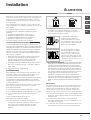
• The room must be equipped with an air extraction system
that expels any combustion fumes. This may consist of a
hood or an electric fan that automatically starts each time
the appliance is switched on.
• The room must also allow proper air circulation, as air is
needed for combustion to occur normally. The flow of air
must not be less than 2 m
3
/h per kW of installed power.
The air circulation system may
take air directly from the outside
by means of a pipe with an inner
cross section of at least 100 cm
2
;
the opening must not be
vulnerable to any type of
blockages.
The system can also provide the
air needed for combustion
indirectly, i.e. from adjacent rooms
fitted with air circulation tubes as
described above. However, these
rooms must not be communal
rooms, bedrooms or rooms that
may present a fire hazard.
• Liquid petroleum gas sinks to the floor as it is heavier
than air. Therefore, rooms containing LPG cylinders must
also be equipped with vents to allow gas to escape in
the event of a leak. As a result LPG cylinders, whether
partially or completely full, must not be installed or
stored in rooms or storage areas that are below ground
level (cellars, etc.). It is advisable to keep only the
cylinder being used in the room, positioned so that it is
not subject to heat produced by external sources
(ovens, fireplaces, stoves, etc. ) which could raise the
temperature of the cylinder above 50°C.
Fitting the appliance
Gas and mixed hobs are manufactured with type X
degree protection against overheating. The following
precautions must be taken when installing the hob:
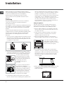
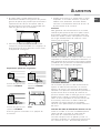
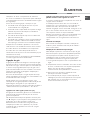
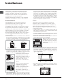
• Kitchen cabinets adjacent to the appliance and taller
than the top of the hob must be at least 600 mm from
the edge of the hob.
• Hoods must be installed according to their relative
installation instruction manuals and at a minimum
distance of 650 mm from the hob.
• Place the wall cabinets adjacent to the hood at a
minimum height of 420 mm from the hob (
see figure
).
If the hob is installed beneath a
wall cabinet, the latter must be
situated at a minimum of 700 mm
above the hob (
see figure
).
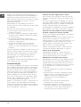
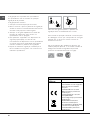
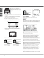
• The installation cavity should have the dimensions
indicated in the figure. Fastening hooks are provided,
allowing you to fasten the hob to tops that are between
20 and 40 mm thick. To ensure the hob is securely
fastened to the top, we recommend you use all the
hooks provided.
555 mm
475
mm
55
mm
• Before fastening the cooktop in place, position the seal
(supplied) along the perimeter of the countertop, as
shown in the figure.
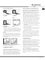
Installation
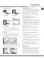
Enlarging the ventilation slot
between window and floor.
Adjacent
Room
Room to be
Vented
A
Examples of ventilation holes
for comburant air.
In a chimney stack or branched flue.
(exclusively for cooking appliances)
Directly to
the Outside
600mm min.
600mm min.
700mm min.

GB
3
Hook fastening diagram
Hooking position Hooking position
for top H=20 mm for top H=30 mm
Front
Hooking position Back
for top H=40 mm
! Use the hooks contained in the “accessory pack”
• Where the hob is not installed over a built-in oven, a
wooden panel must be installed as insulation. This
must be placed at a minimum distance of 20 mm from
the lower part of the hob.
Ventilation
To ensure adequate ventilation, the back panel of the
cabinet must be removed. It is advisable to install the
oven so that it rests on two strips of wood, or on a
completely flat surface with an opening of at least 45 x
560 mm (
see diagrams
).
Where a hob is installed above an oven without a forced
ventilation cooling system, adequate ventilation must be
provided inside the cabinet by means of air holes through
which air can pass (see figure).
Electrical connection
Hobs equipped with a three-pole power supply cable are
designed to operate with alternating current at the voltage
and frequency indicated on the data plate (this is located on
the lower part of the appliance). The earth wire in the cable
has a green and yellow cover. If the appliance is to be
installed above a built-in electric oven, the electrical
connection of the hob and the oven must be carried out
separately, both for electrical safety purposes and to make
extracting the oven easier.
Connecting the supply cable to the mains
Install a standardised plug corresponding to the load
indicated on the data plate.
The appliance must be directly connected to the mains using
an omnipolar circuit-breaker with a minimum contact opening
of 3 mm installed between the appliance and the mains. The
circuit-breaker must be suitable for the charge indicated and
must comply with current electrical regulations (the earthing
wire must not be interrupted by the circuit-breaker). The
supply cable must not come into contact with surfaces with
temperatures higher than 50°C.
! The installer must ensure that the correct electrical
connection has been made and that it is compliant with
safety regulations.
Before connecting to the power supply, make sure that:
• The appliance is earthed and the plug is compliant with
the law.
• The socket can withstand the maximum power of the
appliance, which is indicated on the data plate.
• The voltage is in the range between the values indicated
on the data plate.
• The socket is compatible with the plug of the appliance. If
the socket is incompatible with the plug, ask an
authorised technician to replace it. Do not use extension
cords or multiple sockets.
! Once the appliance has been installed, the power supply
cable and the electrical socket must be easily accessible.
! The cable must not be bent or compressed.
! The cable must be checked regularly and replaced by
authorised technicians only (
see Assistance
).
! The manufacturer declines any liability should these safety
measures not be observed.
Gas connection
The appliance should be connected to the main gas supply
or to a gas cylinder in compliance with current national
regulations. Before carrying out the connection, make sure
the cooker is compatible with the gas supply you wish to
use. If this is not the case, follow the instructions indicated in
the paragraph “Adapting to different types of gas.”
When using liquid gas from a cylinder, install a pressure
regulator which complies with current national regulations.
560 mm.
45 mm.

GB
4
! Check that the pressure of the gas supply is consistent
with the values indicated in Table 1 (“Burner and nozzle
specifications”). This will ensure the safe operation and
longevity of your appliance while maintaining efficient
energy consumption.
Connection with a rigid pipe (copper or steel)
! Connection to the gas system must be carried out in
such a way as not to place any strain of any kind on the
appliance.
There is an adjustable
LL
LL
L-shaped pipe fitting on the
appliance supply ramp and this is fitted with a seal in
order to prevent leaks. The seal must always be replaced
after rotating the pipe fitting (seal provided with
appliance). The gas supply pipe fitting is a threaded 1/2
gas cylindrical male attachment.
Connecting a flexible jointless stainless steel pipe to a
threaded attachment
The gas supply pipe fitting is a threaded 1/2 gas
cylindrical male attachment.
These pipes must be installed so that they are never longer
than 2000 mm when fully extended. Once connection has
been carried out, make sure that the flexible metal pipe
does not touch any moving parts and is not compressed.
! Only use pipes and seals that comply with current
national regulations.
Checking the tightness of the connection
! When the installation process is complete, check the
pipe fittings for leaks using a soapy solution. Never use a
flame.
Adapting to different types of gas
To adapt the hob to a different type of gas other than
default type (indicated on the rating plate at the base of
the hob or on the packaging), the burner nozzles should
be replaced as follows:
1. Remove the hob grids and slide the burners off their
seats.
2. Unscrew the nozzles using a 7 mm socket spanner, and
replace them with nozzles for the new type of gas (see
table 1 “Burner and nozzle characteristics”).
3. Reassemble the parts following the above procedure in
the reverse order.
4. Once this procedure is finished, replace the old rating
sticker with one indicating the new type of gas used.
Sticker are available from any of our Service Centres.
• Adjusting the burners’ primary air :
Does not require adjusting.
• Setting the burners to minimum:
1. Turn the tap to the low flame position.
2. Remove the knob and adjust the adjustment screw,
which is positioned in or next to the tap pin, until the
flame is small but steady.
3. Having adjusted the flame to the required low setting,
while the burner is alight, quickly change the position of
the knob from minimum to maximum and vice versa
several times, checking that the flame does not go out.
4. Some appliances have a safety device (thermocouple)
fitted. If the device fails to work when the burners are
set to the low flame setting, increase this low flame
setting using the adjusting screw.
5. Once the adjustment has been made, replace the seals
on the by-passes using sealing wax or a similar
substance.
! If the appliance is connected to liquid gas, the regulation
screw must be fastened as tightly as possible.
! Once this procedure is finished, replace the old rating
sticker with one indicating the new type of gas used.
Stickers are available from any of our Service Centres.
! Should the gas pressure used be different (or vary
slightly) from the recommended pressure, a suitable
pressure regulator must be fitted to the inlet pipe (in order
to comply with current national regulations).
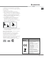
DATA PLAT
E
Electrical
connections
See data plate
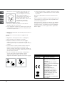
This appliance conforms to the
following European Economic
Community directives:
-2006/95/EEC dated 12/12/06
(Low Voltage) and subsequent
amendments
- 2004/108/EEC dated 15/12/04
(Electromagnetic Compatibility)
and subsequent amendments
- 93/68/EEC dated 22/07/93 and
subsequent amendments.
- 2009/142/EEC dated 30/11/09
(Gas) and subsequent
amendments.
- 2002/96/EC and subsequent
amendments.

GB
5
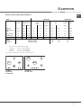
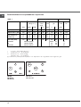
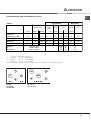
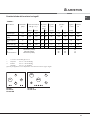
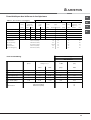
Burner and nozzle specifications
Table 1
Liquid Gas Natural Gas
Burner Diameter
(mm)
Thermal power
kW (p.c.s.*)
By-Pass
1/100
(mm)
Nozzle
1/100
Flow*
g/h
Nozzle
1/100
Flow*
l/h
Nomin. Ridot. (1) (mm) *** ** (mm)
Fast (R)
100 3,00 0,70 41 39 86 218 214 116 286
Reduced Fast
(RR)
100 2,60 0,70 41 39 80 189 186 110 248
Semi Fast (S)
75 1,65 0.40 30 28 64 120 118 96 157
Auxiliary (A)
55 1,00 0,40 30 28 50 73 71 79 95
Mini WOK (MW)
110 3,50 1,30 - 57 94 254 250 138 333
Supply
Pressures
Nominal (mbar)
Minimum (mbar)
Maximum (mbar)
28-30
20
35
37
25
45
20
17
25
* At 15°C and 1013 mbar-dry gas
** Propane P.C.S. = 50.37 MJ/kg.
*** Butane P.C.S. = 49.47 MJ/kg.
Natural P.C.S. = 37.78 MJ/m
3
(1) Only for appliances with the security device.
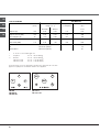
A
S
RS
A
MW
RR
S
S
TQ 751 S
TQ 751 S IX
TD 640
TD 640 IX
TD 640 GH

GB
6
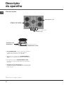
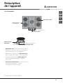
Description of the
appliance
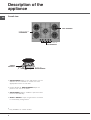
Overall view
*
Only available on certain models.
• GAS BURNERS differ in size and power. Use the
diameter of the cookware to choose the most
appropriate burner to cook with.
• Control Knobs for GAS BURNERS adjust the
power or the size of the flame.
• GAS BURNER ignition* enables a specific burner
to be lit automatically.
• SAFETY DEVICE* stops the gas flow if the flame
is accidentally extinguished.
GAS BURNERS
Support Grid for
COOKWARE
Control Knobs for
GAS BURNERS
SAFETY
DEVICES *
Ignition for
GAS BURNERS *

GB
7
! The position of the corresponding gas burner or electric
hotplate* is shown on every knob.
Gas burners
Each burner can be adjusted to one of the following
settings using the corresponding control knob:
• Off
Maximum
Minimum
To turn on one of the burners, place a lighted match or
lighter near the burner, press the knob all the way in and
turn it anti-clockwise to the "High" setting.
On those models fitted with a safety device, the knob
must be pressed in for about 6 seconds until the device
that keeps the flame lit warms up.
On those models fitted with an ignitor, the ignition button,
identified by the
symbol, must first be pressed and
then the corresponding knob pushed all the way in and
turned anti-clockwise to the "High" setting.
Some models are equipped with an ignition button
incorporated into the control knob. If this is the case, the
ignitor is present, but not the button.
To light a burner, simply press the corresponding knob all
the way in and then turn it anti-clockwise to the "High"
setting, keeping it pressed in until the burner lights.
! If a flame is accidentally extinguished, turn off the control
knob and wait for at least 1 minute before trying to relight
it.
To switch off the burner, turn the knob in a clockwise
direction until it stops (when reaches the “•” position).
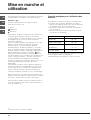
Start-up and use
*
Only available on certain models.
Practical advice on using the burners
To ensure the burners operate efficiently:
• Use appropriate cookware for each burner (see table)
so that the flames do not extend beyond the bottom of
the cookware.
• Always use cookware with a flat base and a cover.
• When the contents of the pan reach boiling point, turn
the knob to minimum.
Burner ø Cookware diameter (cm)
Rapid (R) 24 – 26
Reduced Rapid (RR) 24 – 26
Semi-Rapid (S) 16 – 20
Auxilliary (A) 10 – 14
Mini WOK (MW) 24 – 26
To identify the type of burner, refer to the designs in the
section entitled, "Burner and Nozzle Specifications".

GB
8
Precautions and tips
! This appliance has been designed and
manufactured in compliance with international safety
standards. The following warnings are provided for
safety reasons and must be read carefully.
General safety
• This is a class 3 built-in appliance.
• Gas appliances require regular air exchange to
maintain efficient operation. When installing
the hob, follow the instructions provided in the
paragraph on “Positioning” the appliance.
• These instructions are only valid for the
countries whose symbols appear in the manual
and on the serial number plate.
• The appliance was designed for domestic use
inside the home and is not intended for
commercial or industrial use.
• The appliance must be used by adults only for
the preparation of food, in accordance with the
instructions outlined in this booklet. Any other
use of the appliance (e.g. for heating the room)
constitutes improper use and is dangerous.
The manufacturer may not be held liable for
any damage resulting from improper, incorrect
and unreasonable use of the appliance.
• The appliance must not be installed outdoors, even
in covered areas. It is extremely dangerous to
leave the appliance exposed to rain and storms.
• Do not touch the appliance with bare feet or with
wet or damp hands and feet.
• The appliance must be used by adults only, to
cook food according to the instructions in this
manual.
• Ensure that the power supply cables of other
electrical appliances do not come into contact
with the hot parts of the oven.
• The openings used for ventilation and dispersion
of heat must never be covered.
• Always make sure the knobs are in the “”/“
”
position when the appliance is not in use.
• When unplugging the appliance always pull the plug
from the mains socket, do not pull on the cable.
• Never carry out any cleaning or maintenance work
without having detached the plug from the mains.
• In case of malfunction, under no circumstances
should you attempt to repair the appliance
yourself. Repairs carried out by inexperienced
persons may cause injury or further
malfunctioning of the appliance. Contact a Service
Centre (
see Assistance
).
• Always make sure that pan handles are turned
towards the centre of the hob in order to avoid
accidental burns.
• Do not close the glass cover (if present) when the
gas burners are still hot.
• Do not use unstable or deformed pans.
• The appliance should not be operated by people
(including children) with reduced physical,
sensory or mental capacities, by inexperienced
individuals or by anyone who is not familiar with
the product. These individuals should, at the very
least, be supervised by someone who assumes
responsibility for their safety or receive
preliminary instructions relating to the operation of
the appliance.
• Do not let children play with the appliance.
Disposal
• When disposing of packaging material: observe
local legislation so that the packaging may be
reused.
• The European Directive 2002/96/EC on Waste
Electrical and Electronic Equipment (WEEE),
requires that old household electrical appliances
must not be disposed of in the normal unsorted
municipal waste stream. Old appliances must be
collected separately in order to optimise the
recovery and recycling of the materials they
contain and reduce the impact on human health
and the environment. The crossed out “wheeled
bin” symbol on the product reminds you of your
obligation, that when you dispose of the
appliance it must be separately collected.
Consumers may take their old appliance to public
waste collection areas, other communal collection
areas, or if national legislation allows return it to a
retailer when purchasing a similar new product.
All major household appliance manufacturers are
active in the creation of systems to manage the
collection and disposal of old appliances.

GB
9
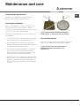
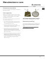
Maintenance and care
Switching the appliance off
Disconnect your appliance from the electricity
supply before carrying out any work on it.
Cleaning the appliance
! Do not use abrasive or corrosive detergents such
as stain removers, anti-rust products, powder
detergents or sponges with abrasive surfaces: these
may scratch the surface beyond repair.
! Never use steam cleaners or pressure cleaners on
the appliance.
• It is usually enough to wash the hob with a damp
sponge and dry it with absorbent kitchen roll.
• The removable parts of the burners should be
washed frequently with warm water and soap and
any burnt-on substances removed.
• For hobs which ligth automatically, the terminal
part of the electronic instant lighting devices
should be cleaned frequently and the gas outlet
holes should be checked for blockages.
• Stainless steel can be marked by hard water that
has been left on the surface for a long time, or by
aggressive detergents containing phosphorus.
After cleaning, rinse and dry any remaining drops
of water.
! Do not use stainless steel flame spreaders,
bread toasters or meat grills over gas flames.
Gas tap maintenance
Over time, the taps may become jammed or difficult
to turn. If this happens, the tap must be replaced.
! This procedure must be performed by a
qualified technician authorised by the
manufacturer.

GB
10
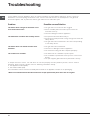
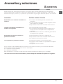
Troubleshooting
It may happen that the appliance does not function properly or at all. Before calling the service centre for
assistance, check if anything can be done. First, check to see that there are no interruptions in the gas and
electrical supplies, and, in particular, that the gas valves for the mains are open.
Problem
The burner does not light or the flame is not
even around the burner.
The flame dies in models with a safety device.
The burner does not remain lit when set to
minimum.
The cookware is unstable.
Possible causes/Solution
• The gas holes on the burner are clogged.
• All the movable parts that make up the burner are
mounted correctly.
• There are draughts near the appliance.
• You pressed the knob all the way in.
• You keep the knob pressed in long enough to activate the
safety device.
• The gas holes are not blocked in the area corresponding
to the safety device.
• The gas holes are not blocked.
• There are no draughts near the appliance.
• The minimum setting has been adjusted properly.
• The bottom of the cookware is perfectly flat.
• The cookware is positioned correctly at the centre of the
burner.
• The pan support grids have been positioned correctly.
If, despite all these checks, the hob does not function properly and the problem persists, call the nearest
Customer Service Centre. Please have the following information handy:
• The appliance model (Mod.).
• The serial number (S/N).
This information can be found on the data plate located on the appliance and/or on the packaging.
! Never use unauthorised technicians and never accept replacement parts which are not original.

ES
ENCIMERA
TD 640
TD 640 IX
TD 640 GH
TQ 751 S
TQ 751 S IX
Sumario
Instalación, 12-16
Colocación
Conexión eléctrica
Conexión gas
Placa de características
Características de los quemadores e inyectores
Descripción del aparato, 17
Vista de conjunto
Puesta en funcionamiento y uso, 18
Consejos prácticos para el uso de los quemadores
Precauciones y consejos, 19
Seguridad general
Eliminación
Mantenimiento y cuidados, 20
Cortar la corriente eléctrica
Limpiar el aparato
Mantenimiento de las llaves de gas
Placa de características
Anomalías y soluciones, 21
Manual de instrucciones
English, 1
GB
Português, 22
PT
ES
Español, 11
Italiano, 33
IT
Français, 44
FR

ES
12
! Es importante conservar este manual para poder
consultarlo en todo momento. En caso de venta, de
cesión o de mudanza, verifique que permanezca
junto al aparato para informar al nuevo propietario
sobre su funcionamiento y sobre las advertencias
correspondientes.
! Lea atentamente las instrucciones: contienen
importante información sobre la instalación, el uso y
la seguridad.
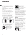
Colocación
! Los embalajes no son juguetes para niños y se
deben eliminar respetando las normas para la
recolección de residuos (
ver Precauciones y consejos
).
! La instalación se debe realizar siguiendo estas
instrucciones y por personal profesionalmente
calificado. Una instalación incorrecta puede producir
daños a personas, animales o cosas.
! Este aparato puede ser instalado y funcionar sólo
en lugares ventilados permanentemente, de acuerdo
a las prescripciones de l’Orden de 29.03.1974.
Deben ser observados los siguentes requisitos:
• El ambiente debe poseer un sistema de descarga
de los humos de la combustión al exterior,
utilizando una campana o un electroventilador
que entre automáticamente en funcionamiento
cada vez que se enciende el aparato.
• El ambiente debe poseer un sistema que permita
la entrada del aire necesario para una combustión
normal. El caudal de aire necesario para la
combustión no debe ser inferior a 2 m
3
/h por cada
kilovatio (kW) de potencia instalada.
El sistema puede tomar aire
del exterior del edificio a
través de un conducto de 100
cm
2
, como mínimo, de
sección útil de modo que no
pueda ser obstruido
accidentalmente.
También puede hacerlo de
manera indirecta, desde
ambientes adyacentes que
posean un conducto de
ventilación hacia el exterior,
como se describe más arriba,
y que no sean partes en
común del inmueble,
ambientes con peligro de
incendio o dormitorios.
• Los gases de petróleo licuados, más pesados que
el aire, se depositan en las partes más bajas. Por lo
tanto, los ambientes que contienen botellas de GPL
deben tener aberturas hacia el exterior para permitir
la evacuación desde abajo de eventuales escapes
de gas. Además, las botellas de GPL, vacías o
parcialmente llenas, no deben ser instaladas o
depositadas en ambientes o espacios a un nivel
más bajo del suelo (sótanos, etc.) Es conveniente
conservar en el ambiente sólo la botella que se está
utilizando, colocada de modo que no quede
expuesta a la acción directa de fuentes de calor
(hornos, chimeneas, estufas, etc.) capaces de
llevarla a temperaturas superiores a 50°C.
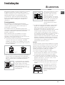
Empotramiento
Las encimeras a gas y mixtas están fabricadas con un
grado de protección contra calentamientos excesivos de
tipo X, y por lo tanto, es posible su instalación al lado de
muebles cuya altura no supere la de la superficie de
trabajo. Para una correcta instalación de la encimera se
deben observar las siguientes precauciones:
• Los muebles situados a un costado, cuya altura
supere la de la superficie de trabajo, deben estar
situados a 600 mm., como mínimo, del borde de
la misma.
• Las campanas deben ser instaladas de acuerdo
con los requisitos establecidos en los manuales
de instrucción de las mismas, siempre
manteniendo una distancia mínima de 650 mm.
• Coloque los armarios de pared adyacentes a la
campana a una altura mínima desde la superficie
de trabajo, de 420 mm. (
ver la figura
).
Siempre que la encimera se
instale debajo de un armario
de pared, éste último deberá
mantener una distancia
mínima de la superficie de
trabajo de 700 mm. (
ver la
figura
).
Instalación
Aumento de la ranura entre
puerta y suelo
Habitación
adyacente
Habitación
por ventilar
A
Ejemplos de aperture
de ventilación
para aire comburente
En chimenea o tubo de chimenea ramificado
(reservado a los aparatos de cocción)
Directamente
al externo
600mm min.
600mm min.
700mm min.

ES
13
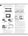
• El espacio para el mueble deberá tener las
dimensiones indicadas en la figura. Se han previsto
ganchos de fijación que permiten fijar la encimera a
superficies de 20 a 40 mm. de espesor. Para un
buena fijación de la encimera, es aconsejable usar
todos los ganchos que se suministran.
555 mm
475
mm
55
mm
• Antes de proceder a la fijación a la encimera,
coloque la junta (suministrada con el equipo) a lo
largo del perímetro de la placa de cocción como
se representa en la figura.
Esquema de fijación de los ganchos
Posición del gancho para Posición del gancho para
superficies
H=20mm superficies H=30mm
Adelante
Posición del gancho para Atrás
superficies
H=40mm
! Use los ganchos contenidos en el “paquete de
accesorios”
• Cuando la encimera no se instale sobre un horno
empotrado, es necesario introducir un panel de
madera como aislamiento. El mismo deberá
colocarse a una distancia mínima de 20 mm. de
la pared inferior de la encimera.
Aireación
Para garantizar una buena aireación es necesario
eliminar la pared posterior del hueco para el horno.
Es preferible instalar el horno apoyado sobre dos
listeles de madera o sobre una superficie continua
que tenga una abertura de 45 x 560 mm. como
mínimo (
ver las figuras
).
Cuando la instalación se realice sobre un horno
empotrado sin ventilación forzada de enfriamiento, se
debe garantizar la presencia de tomas para la entrada
y salida de aire que permitan una adecuada aireación
en el interior del mueble (ver las figuras).
Conexión eléctrica
Las encimeras que poseen cable de alimentación
tripolar, se fabrican para funcionar con corriente
alterna, a la tensión y frecuencia de alimentación
indicadas en la placa de características (ubicada en
la parte inferior de la encimera). El conductor de
puesta a tierra del cable se distingue por los colores
amarillo-verde. Cuando se realiza la instalación
sobre un horno empotrado, la conexión eléctrica de
la encimera y la del horno se deben realizar por
separado, ya sea por razones de seguridad
eléctrica, como para facilitar la eventual extracción
del horno.
Conexión del cable de alimentación eléctrica a la red
Instale en el cable un enchufe normalizado para la
carga indicada en la placa de características.
En el caso de conexión directa a la red, es
necesario interponer entre el aparato y la red, un
interruptor omnipolar con una distancia mínima entre
los contactos de 3 mm., dimensionado para esa
560 mm.
45 mm.

ES
14
carga y que responda a las normas vigentes (el
conductor de tierra no debe ser interrumpido por el
interruptor). El cable de alimentación eléctrica se
debe colocar de modo tal que no alcance en ningún
punto una temperatura que supere en 50°C la
temperatura ambiente.
! El instalador es responsable de la correcta
conexión eléctrica y del cumplimiento de las normas
de seguridad.
Antes de efectuar la conexión verifique que:
• la toma tenga conexión a tierra y que sea
conforme con la ley;
• la toma sea capaz de soportar la carga máxima
de potencia de la máquina indicada en la placa
de características;
• la tensión de alimentación eléctrica esté
comprendida dentro de los valores indicados en
la placa de características;
• la toma sea compatible con el enchufe del
aparato. Si no es así, sustituya la toma o el
enchufe; no utilice prolongaciones ni conexiones
múltiples.
! Una vez instalado el aparato, el cable eléctrico y la
toma de corriente deben ser fácilmente accesibles.
! El cable no debe sufrir pliegues ni compresiones.
! El cable debe ser revisado periódicamente y
sustituido sólo por técnicos autorizados (
ver
Asistencia
).
! La empresa declina toda responsabilidad cuando
estas normas no sean respetadas.
Conexión de gas
La conexión del aparato a la tubería o a la botella de
gas se deberá efectuar de acuerdo a lo prescripto
por las Normas Nacionales vigentes, sólo después
de haber verificado que el mismo está regulado
para el tipo de gas con el cual será alimentado. Si
no es así, realice las operaciones indicadas en el
párrafo “Adaptación a los distintos tipos de gas”.
En el caso de alimentación con gas líquido, desde
botella, utilice reguladores de presión conformes
con las Normas Nacionales vigentes.
! Para un funcionamiento seguro, un adecuado uso
de la energía y una mayor duración del aparato,
verifique que la presión de alimentación cumpla con
los valores indicados en la tabla 1 “Características
de los quemadores e inyectores”.
Conexión con tubo rígido (cobre o acero)
! La conexión a la red de gas se debe efectuar de
modo que no provoque esfuerzos de ningún tipo al
aparato.
En el tubo de alimentación del aparato se encuentra
una unión en “
LL
LL
L” orientable, cuya estanqueidad está
asegurada por una junta. Si resultara necesario girar
la unión, sustituya siempre la junta estanca
(suministrada con el aparato). La unión de entrada de
gas al aparato es roscada 1/2 gas macho cilíndrico.
Conexión con tubo flexible de acero inoxidable
de pared continua con uniones roscadas
La unión de entrada de gas al aparato es roscada 1/
2 gas macho cilíndrico.
La colocación de dichos tubos se debe efectuar de
modo tal que su longitud, en condiciones de
máxima extensión, no sea mayor que 2000 mm. Una
vez realizada la conexión, verifique que el tubo
metálico flexible no permanezca en contacto con
partes móviles o no quede aplastado.
! Utilice exclusivamente tubos y juntas estancas
conformes a la Normas Nacionales en vigencia.
Control de la estanqueidad
! Finalizada la instalación, controle la perfecta
estanqueidad de todas las uniones utilizando una
solución jabonosa pero nunca una llama.
Adaptación a los distintos tipos de gas
Para adaptar la encimera a un tipo de gas diferente
de aquel para el que fue fabricada (indicado en la
etiqueta fijada en la parte inferior de la encimera o
en el embalaje), es necesario sustituir los inyectores
de los quemadores efectuando las siguientes
operaciones:
1. quite las parrillas de la encimera y extraiga los
quemadores.
2. desenrosque los inyectores utilizando una llave
tubular de 7mm. y sustitúyalos por los que se
adapten al nuevo tipo de gas (ver tabla 1
“Características de los quemadores e
inyectores”).
3. vuelva a colocar las piezas realizando las
operaciones en sentido contrario.
4. al finalizar la operación, sustituya la anterior
etiqueta de calibrado con la correspondiente al
nuevo gas que se va a utilizar, disponible en
nuestros Centros de Asistencia Técnica.

ES
15
• Regulación de aire principal de los quemadores
Los quemadores no necesitan de ninguna regulación
de aire principal.
• Regulación de los mínimos
1. Lleve la llave hasta la posición de mínimo;
2. Quite el mando y accione el tornillo de regulación
situado en el interior o al costado de la varilla de la
llave hasta conseguir una pequeña llama regular.
3. Verifique que girando rápidamente el mando
desde la posición de máximo hasta la de mínimo,
no se apaguen los quemadores.
4. En los aparatos provistos del dispositivo de
seguridad (termopar), si dicho dispositivo no
funcionara con los quemadores al mínimo,
aumente la capacidad de los mínimos utilizando
para ello el tornillo de regulación.
5. Una vez efectuada la regulación, vuelva a colocar
los precintos ubicados en los by-pass con lacre o
un material equivalente.
! En el caso de gas líquido, el tornillo de regulación
deberá enroscarse a fondo.
! Al finalizar la operación, sustituya la anterior
etiqueta de calibrado con la correspondiente al
nuevo gas que se va a utilizar, disponible en
nuestros Centros de Asistencia Técnica.
! Cuando la presión del gas utilizado sea distinta de
la prevista (o variable), es necesario instalar, en la
tubería de entrada, un regulador de presión
conforme con las Normas Nacionales en vigencia.
PLACA DE CARACTER
Í
STICAS
Conexiones
eléctricas
ver placa de características
Este aparato es conforme con
las siguientes Normas
Comunitarias:
- 2006/95/CEE del 12/12/06
(Baja Tensión) y posteriores
modificaciones
- 2004/108/CEE del 15/12/04
(Compatibilidad
Electromagnética) y posteriores
modificaciones
- 93/68/CEE del 22/07/93 y
posteriores modificaciones.
- 90/336/CEE del 29/06/90 (Gas)
y posteriores modificaciones.
- 2002/96/CEE y posteriores
modificaciones.

ES
16
Características de los quemadores e inyectores
Tabla 1
Gas liquido Gas natural
Quemador Diametro Potencia térmica
kW (p.c.s.*)
By-Pass
1/100
(mm)
pico
1/100
capacid.*
g/h
pico
1/100
capacid.*
l/h
(mm) Nomin. Reduc. (1) (mm) *** ** (mm)
Ràpido (R)
100 3,00 0,70 41 39 86 218 214 116 286
Ràpido Reduc. (RR)
100 2,60 0,70 41 39 80 189 186 110 248
Semi Ràpido (S)
75 1,65 0.40 30 28 64 120 118 96 157
Auxiliari (A)
55 1,00 0,40 30 28 50 73 71 79 95
Mini WOK (MW)
110 3,50 1,30 - 57 94 254 250 138 333
Presiones
de
suministro
Nominal (mbar)
Minimo (mbar)
Màximo (mbar)
28-30
20
35
37
25
45
20
17
25
* A 15°C y 1013 mbar-gas seco
** Propano P.C.S. = 50.37 MJ/kg.
*** Butano P.C.S. = 49.47 MJ/kg.
Natural P.C.S. = 37.78 MJ/m
3
(1) Únicamente para aquellos aparatos con dispositivos de seguridad contra fugas de gas
A
S
RS
A
MW
RR
S
S
TQ 751 S
TQ 751 S IX
TD 640
TD 640 IX
TD 640 GH

ES
17
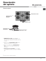
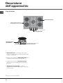
Descripción
del aparato
Vista de conjunto
*
Presente sólo en algunos modelos.
• QUEMADORES A GAS: son de distintas
dimensiones y potencias. Elija siempre el más
adecuado para el diámetro del recipiente que va
a utilizar.
• Mandos de los QUEMADORES A GAS para la
regulación de la llama o de la potencia.
• Bujía de encendido de los QUEMADORES A
GAS:* permite el encendido automático del
quemador.
• DISPOSITIVO DE SEGURIDAD:* si se apaga
accidentalmente la llama, interrumpe la salida de
gas.
DISPOSITIVO DE
SEGURIDAD *
Bujía de encendido de los
QUEMADORES A GAS *
QUEMADORES A GAS
Parrillas de apoyo para
RECIPIENTES DE
COCCIÓN
Mandos de los
QUEMADORES A GAS

ES
18
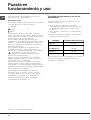
Puesta en
funcionamiento y uso
! En cada mando está indicada la posición del
quemador a gas correspondiente.
Quemadores a gas
El quemador elegido se puede regular con el mando
correspondiente de la siguiente manera:
• Apagado
Máximo
Mínimo
Para encender uno de los mecheros, acercar al
mismo una llama o un encendedor, apretar a fondo y
girar el botón correspondiente en sentido antihorario
hasta la posición de máxima potencia.
En los modelos dotados del dispositivo de
seguridad, es necesario mantener apretado el botón
durante 6 segundos aproximadamente hasta que se
caliente el dispositivo que mantiene encendida la
llama automáticamente.
En los modelos dotados de encendedor, para
encender el mechero elegido, apretar primero el
pulsador de encendido, identificado con el símbolo
, luego apretar a fondo y girar el botón
correspondiente en sentido antihorario hasta la
posición de máxima potencia.
Algunos modelos están dotados de encendido
integrado dentro del botón, en este caso existe el
encendedor pero no el pulsador.
Para encender el mechero elegido es suficiente
primero apretar a fondo el botón correspondiente,
luego girarlo en sentido antihorario hasta la posición
de máxima potencia, manteniéndolo apretado hasta
que se produzca el encendido.
! Si se apagara accidentalmente la llama del
quemador, cierre el mando y vuelva a intentar
encenderlo después de 1 minuto, como mínimo.
Para apagar el quemador es necesario girar el
mando en sentido horario hasta el apagado
(correspondiente al símbolo “•”).
Consejos prácticos para el uso de los
quemadores
Si desea obtener el máximo rendimiento, es útil
recordar lo siguiente:
• utilice recipientes adecuados para cada
quemador (ver la tabla) con el fin de evitar que
las llamas sobresalgan por el fondo de los
recipientes.
• utilice siempre recipientes con el fondo plano y
con tapa.
• cuando se produce la ebullición, gire el mando
hasta la posición de mínimo.
Quemador ø Diámetro Recipientes(cm)
Rápido (R) 24 – 26
Rápido Reducido (RR) 24 – 26
Semi Rápido (S) 16 – 20
Auxiliar (A) 10 – 14
Mini WOK (MW) 24 – 26
Para identificar el tipo de quemador ver los diseños
presentes en el párrafo "Características de los
quemadores y boquillas".
*
Presente sólo en algunos modelos.

ES
19
Precauciones y consejos
! El aparato ha sido proyectado y fabricado en
conformidad con las normas internacionales de
seguridad. Estas advertencias se suministran por
razones de seguridad y deben ser leídas
atentamente.
Seguridad general
• Este aparato se refiere a un aparato empotrable
de clase 3.
• Para su correcto funcionamiento, los aparatos
a gas necesitan un regular cambio de aire.
Verifique que en su instalación se respeten los
requisitos contenidos en el párrafo
correspondiente a la “Colocación”.
• Las instrucciones son válidas sólo para los
países de destino, cuyos símbolos figuran en
el manual y en la placa de características.
• El aparato ha sido fabricado para un uso de tipo
no profesional en el interior de una vivienda.
• El aparato debe ser utilizado para cocinar
alimentos, sólo por personas adultas y
siguiendo las instrucciones contenidas en este
manual. Cualquier otro uso (como por
ejemplo: calefacción de ambientes) se debe
considerar impropio y, por lo tanto, peligroso.
El fabricante no puede ser considerado
responsable por los daños derivados de usos
impropios, erróneos e irracionales.
• El aparato no se debe instalar al aire libre,
tampoco si el espacio está protegido porque es
muy peligroso dejarlo expuesto a la lluvia y a las
tormentas.
• No toque la máquina descalzo o con las manos y
pies mojados o húmedos.
• El aparato debe ser utilizado para cocinar
alimentos, sólo por personas adultas y siguiendo
las instrucciones contenidas en este manual.
• Evite que el cable de alimentación eléctrica de
otros electrodomésticos entre en contacto con
partes calientes del horno.
• No obstruya las aberturas de ventilación y de
eliminación del calor.
• Controle siempre que los mandos estén en la
posición “”/“
” cuando no se utiliza el aparato.
• No desconecte el aparato de la toma de corriente
tirando del cable sino sujetando el enchufe.
• No realice la limpieza o el mantenimiento sin
haber desconectado primero el aparato de la red
eléctrica.
• En caso de avería, no acceda nunca a los
mecanismos internos para intentar una
reparación. Llame al Servicio de Asistencia
Técnica (
ver Asistencia
).
• Verifique que los mangos de las ollas estén
siempre dirigidos hacia dentro de la encimera
para evitar que sean chocados accidentalmente.
• No cierre la tapa de vidrio (si existe) cuando los
quemadores todavía están calientes.
• No utilice ollas inestables o deformadas.
• No está previsto que el aparato sea utilizado por
personas (niños incluidos) con reducidas
capacidades físicas, sensoriales o mentales, por
personas inexpertas o que no tengan familiaridad
con el producto, a menos que no sean vigiladas
por una persona responsable de su seguridad o
que no hayan recibido instrucciones preliminares
sobre el uso del aparato.
• Evitar que los niños jueguen con el aparato.
Eliminación
• Eliminación del material de embalaje: respete las
normas locales, de esta manera los embalajes
podrán ser reutilizados.
• En base a la Norma europea 2002/96/CE de
Residuos de aparatos Eléctricos y Electrónicos
(RAEE), los electrodomésticos viejos no pueden
ser arrojados en los contenedores municipales
habituales; tienen que ser recogidos
selectivamente para optimizar la recuperación y
reciclado de los componentes y materiales que
los constituyen, y reducir el impacto en la salud
humana y el medioambiente. El símbolo del cubo
de basura tachado se marca sobre todos los
productos para recordar al consumidor la
obligación de separarlos para la recogida
selectiva.
El consumidor podrá llevar los electrodomésticos
viejos a las áreas especiales preparadas por las
administraciones municipales, entregarlos al
servicio público de recogida o, si la legislación
nacional lo contempla, entregarlos en la tienda al
hacer la compra de los electrodomésticos nuevos
de tipología análoga.
Todos los principales productores están
involucrados en la creación y gestión de sistemas
optimizados para la recogida y eliminación de los
residuos de los electrodomésticos.

ES
20
Mantenimiento y cuidados
Cortar la corriente eléctrica
Antes de realizar cualquier operación, desconecte el
aparato de la red de alimentación eléctrica.
Limpiar el aparato
! Evite el uso de detergentes abrasivos o corrosivos
como los quitamanchas y productos anticorrosivos,
jabones en polvo y esponjas con superficie
abrasiva: pueden rayar irremediablemente la
superficie.
! No utilice nunca limpiadores a vapor o de alta
presión para la limpieza del aparato.
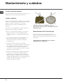
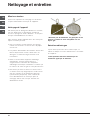
• Para un mantenimiento ordinario, es suficiente
lavar la encimera con una esponja húmeda,
secándola luego con un papel absorbente para
cocina.
• Los elementos móviles de los quemadores se
lavan frecuentemente con agua caliente y
detergente tratando siempre de eliminar las
incrustaciones.
• En las encimeras que poseen encendido
automático, es necesario realizar frecuentemente
una cuidadosa limpieza de la parte terminal de
los dispositivos de encendido instantáneo
electrónico y verificar que los orificios de salida
del gas no estén obstruidos.
• El acero inoxidable puede quedar manchado si
permanece en contacto por largo tiempo con
agua fuertemente calcárea o con detergentes
agresivos (que contengan fósforo). Se aconseja
enjuagar abundantemente y secar después de la
limpieza. Es además importante secar los
posibles derrames de agua.
! No utilice difusores, tostadores de pan o
parrillas para carne de acero inoxidable sobre los
mecheros a gas.
Mantenimiento de las llaves de gas
Con el tiempo puede suceder que una llave se
bloquee o presente dificultad para girar, en esos
casos será necesario proceder a la sustitución de
dicha llave.
! Esta operación la debe efectuar un técnico
autorizado por el fabricante.
A página está carregando...
A página está carregando...
A página está carregando...
A página está carregando...
A página está carregando...
A página está carregando...
A página está carregando...
A página está carregando...
A página está carregando...
A página está carregando...
A página está carregando...
A página está carregando...
A página está carregando...
A página está carregando...
A página está carregando...
A página está carregando...
A página está carregando...
A página está carregando...
A página está carregando...
A página está carregando...
A página está carregando...
A página está carregando...
A página está carregando...
A página está carregando...
A página está carregando...
A página está carregando...
A página está carregando...
A página está carregando...
A página está carregando...
A página está carregando...
A página está carregando...
A página está carregando...
A página está carregando...
A página está carregando...
A página está carregando...
A página está carregando...
-
 1
1
-
 2
2
-
 3
3
-
 4
4
-
 5
5
-
 6
6
-
 7
7
-
 8
8
-
 9
9
-
 10
10
-
 11
11
-
 12
12
-
 13
13
-
 14
14
-
 15
15
-
 16
16
-
 17
17
-
 18
18
-
 19
19
-
 20
20
-
 21
21
-
 22
22
-
 23
23
-
 24
24
-
 25
25
-
 26
26
-
 27
27
-
 28
28
-
 29
29
-
 30
30
-
 31
31
-
 32
32
-
 33
33
-
 34
34
-
 35
35
-
 36
36
-
 37
37
-
 38
38
-
 39
39
-
 40
40
-
 41
41
-
 42
42
-
 43
43
-
 44
44
-
 45
45
-
 46
46
-
 47
47
-
 48
48
-
 49
49
-
 50
50
-
 51
51
-
 52
52
-
 53
53
-
 54
54
-
 55
55
-
 56
56


Ariston TD 640 (ICE) GH Guia de usuario
- Categoria
- Fogões
- Tipo
- Guia de usuario
- Este manual também é adequado para
em outras línguas
- español: Ariston TD 640 (ICE) GH Guía del usuario
- français: Ariston TD 640 (ICE) GH Mode d'emploi
- italiano: Ariston TD 640 (ICE) GH Guida utente
Artigos relacionados
-
Ariston PF 640 E (WH) Manual do proprietário
-
Indesit TQ 751 (ICE) K X Guia de usuario
-
Ariston TD 640 S (BK) IX Guia de usuario
-
Ariston TD 640 S (BK) IX Guia de usuario
-
-
-
-
-
Indesit PKLL 641 D2/IX/A Guia de usuario
Outros documentos
-
-
CONTINENTAL EDISON CECP9060MID Manual do usuário
-
Whirlpool SCHG 640 GH Manual do proprietário
-
-
-
-
-