Tamaha RP-U200 Manual do usuário
- Categoria
- Receptor
- Tipo
- Manual do usuário

1
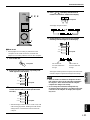
PERSONAL RECEIVER
RP-U200
OPERATION MANUAL
MANUEL D’UTILISATION
U C A
PC
AUX1
AUX2
TUNER
DSP P-SET
VOL
VIRTUAL
5.I
CH
DIGITAL
PROLOGIC FM AM ST
USB PCM D.
DSP
POWER
PC
AUX1
AUX2
TUNER
JAZZ CHURCHHALL
B
VOLUMEMUTE
CA
MOVIE LIVE
PRESET MANUALMEMORY
GAME
TEST
ON
/
OFF
/DTS
SURROUND

2
• Explanation of Graphical Symbols
The lightning flash with arrowhead
symbol, within an equilateral triangle,
is intended to alert you to the
presence of uninsulated “dangerous
voltage” within the product’s
enclosure that may be of sufficient
magnitude to constitute a risk of
electric shock to persons.
The exclamation point within an
equilateral triangle is intended to alert
you to the presence of important
operating and maintenance
(servicing) instructions in the
literature accompanying the
appliance.
IMPORTANT SAFETY INSTRUCTIONS
1 Read these instructions.
2 Keep these instructions.
3 Heed all warnings.
4 Follow all instructions.
5 Do not use this apparatus near water.
6 Clean only with dry cloth.
7 Do not block any ventilation openings. Install in
accordance with the manufacturer’s instructions.
8 Do not install near any heat sources such as radiators,
heat registers, stoves, or other apparatus (including
amplifiers) that produce heat.
9 Do not defeat the safety purpose of the polarized or
grounding-type plug. A polarized plug has two blades
with one wider than the other. A grounding type plug
has two blades and a third grounding prong. The wide
blade or the third prong are provided for your safety. If
the provided plug does not fit into your outlet, consult
an electrician for replacement of the obsolete outlet.
10 Protect the power cord from being walked on or
pinched particularly at plugs, convenience receptacles,
and the point where they exit from the apparatus.
11 Only use attachments/accessories specified by the
manufacturer.
12 Use only with the cart, stand, tripod,
bracket, or table specified by the
manufacturer, or sold with the
apparatus. When a cart is used, use
caution when moving the cart/
apparatus combination to avoid injury
from tip-over.
13 Unplug this apparatus during lightning storms or when
unused for long periods of time.
14 Refer all servicing to qualified service personnel.
Servicing is required when the apparatus has been
damaged in any way, such as power-supply cord or
plug is damaged, liquid has been spilled or objects
have fallen into the apparatus, the apparatus has been
exposed to rain or moisture, does not operate normally,
or has been dropped.
WARNING
TO REDUCE THE RISK OF FIRE OR ELECTRIC
SHOCK, DO NOT EXPOSE THIS APPLIANCE TO RAIN
OR MOISTURE.
CAUTION
CAUTION: TO REDUCE THE RISK OF
ELECTRIC SHOCK, DO NOT REMOVE
COVER (OR BACK). NO USER-SERVICEABLE
PARTS INSIDE. REFER SERVICING TO
QUALIFIED SERVICE PERSONNEL.
RISK OF ELECTRIC SHOCK
DO NOT OPEN
IMPORTANT
Please record the serial number of this system in the
space below.
Model:
Serial No.:
The serial number is located on the rear of the main
unit.
Retain this Owner’s Manual in a safe place for future
reference.

3
We Want You Listening For A Lifetime
YAMAHA and the Electronic Industries Association’s
Consumer Electronics Group want you to get the most out
of your equipment by playing it at a safe level. One that lets
the sound come through loud and clear without annoying
blaring or distortion – and, most importantly, without
affecting your sensitive hearing.
Since hearing damage from loud sounds is
often undetectable until it is too late, YAMAHA
and the Electronic Industries Association’s
Consumer Electronics Group recommend you
to avoid prolonged exposure from excessive
volume levels.
FCC INFORMATION (for US customers only)
1. IMPORTANT NOTICE: DO NOT MODIFY THIS UNIT!
This product, when installed as indicated in the instructions contained in this manual, meets FCC requirements.
Modifications not expressly approved by Yamaha may void your authority, granted by the FCC, to use the product.
2. IMPORTANT: When connecting this product to accessories and/or another product use only high quality shielded
cables. Cable/s supplied with this product MUST be used. Follow all installation instructions. Failure to follow
instructions could void your FCC authorization to use this product in the USA.
3. NOTE: This product has been tested and found to comply with the requirements listed in FCC Regulations, Part 15 for
Class “B” digital devices. Compliance with these requirements provides a reasonable level of assurance that your use
of this product in a residential environment will not result in harmful interference with other electronic devices. This
equipment generates/uses radio frequencies and, if not installed and used according to the instructions found in the
users manual, may cause interference harmful to the operation of other electronic devices. Compliance with FCC
regulations does not guarantee that interference will not occur in all installations. If this product is found to be the
source of interference, which can be determined by turning the product “OFF” and “ON”, please try to eliminate the
problem by using one of the following measures:
Relocate either this product or the device that is being affected by the interference.
Utilize power outlets that are on different branch (circuit breaker or fuse) circuits or install AC line filter/s.
In the case of radio or TV interference, relocate/reorient the antenna. If the antenna lead-in is 300 ohm ribbon lead,
change the lead-in to coaxial type cable.
If these corrective measures do not produce satisfactory results, please contact the local retailer authorized to
distributethis type of product. If you can not locate the appropriate retailer, please contact Yamaha Electronics Corp.,
6660 Orangethorpe Ave. Buena Park, CA90620
The above statements apply ONLY to those products distributed by Yamaha Corporation of America or its
subsidiaries.
COMPLIANCE INFORMATION STATEMENT
(DECLARATION OF CONFORMITY PROCEDURE)
Responsible Party:
Address:
Telephone:
Type of Equipment:
Model Name:
Yamaha Electronics Corp.,
6660 Orangethorpe Ave.
Buena Park, CA90620
714-522-9105
Receiver
RP-U200
This device complies with Part 15 of the FCC Rules.
Operation is subject to the following conditions:
1) this device may not cause harmful interference, and
2) this device must accept any interference received including interference that may cause undesired operation.
See the user manual instructions if interference to radio reception is suspected.

4
INTRODUCTION
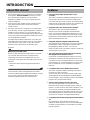
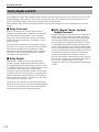
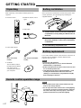
Features
● This unit brings high-quality audio to your
computer
This unit is a multimedia amplifier that brings you a new
level of audio enjoyment. This unit has a USB port for
connection with a personal computer. The USB interface
allows remote control of this unit from your computer and
control of sound data sent from your computer.
● Equipped with a five-channel power amplifier
This unit has a five-channel power amplifier for
reproducing surround sound fields of Dolby Digital*,
DTS** and Yamaha CINEMA-DSP effectively. You can
enjoy a full-scale home theater sound simply by adding
the optional Yamaha speaker system NS-U40P and an
optional subwoofer to this unit.
● Equipped with Dolby Digital and DTS decoders
This unit reproduces multichannel sources encoded with
Dolby Digital* or DTS** faithfully by using the built-in
Dolby Digital and DTS decoders. You can now
experience the sound scale and the realistic sensation of
actual theaters in your home.
● The newly-developed Yamaha Near-Field Cinema
DSP (Digital Sound Field Processor)
Various DSP sound field programs allow you to select
the program suitable for the selected input source. You
can experience the sound fields of famous concert halls,
movie theaters, etc. around the world in your home. The
DSP sound effects are also available for headphone
listening.
● Compatible with various USB audio functions
This unit is compatible with the following audio signals
received via a USB connection:
multi-channel (two, four and six channels) audio, high
quality digital audio of 24 bit/48 kHz and Dolby Digital-
encoded signals. (Some operating systems and software
programs do not support this feature.)
● Various inputs/outputs and easy operation
This unit is equipped with various input and output
terminals for both analog and digital signals, making it
ideal as a control center for other audio equipment, such
as a personal computer, CD player and MD recorder.
The supplied remote control makes operation easy, and
the supplied Application Software allows control of this
unit from your computer including detailed settings.
● Compatible with Virtual Dolby Digital and DTS Virtual
5.1
By employing the Virtual 3D technology, this unit
reproduces multi-channel sources such as Dolby Digital
and DTS providing realistic surround effects even with
just two speakers.
About this manual
● This manual explains how to operate this unit. Refer to
the separate “SET UP MANUAL” for how to connect
this unit with other equipment, and to install the
Application Software, etc. to your computer from the
supplied CD-ROM.
● This manual mainly explains how to operate this unit
using the front panel of this unit and the supplied
remote control.
● When this unit and your computer are connected with
the USB cable, and the supplied Application Software is
installed on the computer, you can operate this unit
from the computer using the Application Software. Refer
to the online help of the Application Software for how to
use the Application Software.
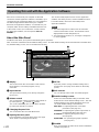
The Application Software extends the use of this unit
with additional functions which cannot be used with the
front panel keys or the remote control. This manual
introduces those functions by the following style.
Example:
Adjusting USB MIX LEVEL
When an input other than the USB terminal is selected,
you can listen to the mixed sound signals from the
selected input and from the USB terminal. Also, the
mixing ratio of the signals from the USB terminal can be
adjusted.
* Refer to the online help of the Application Software for
details.
This manual also offers brief explanations about the
functions available with the Application Software on page
22–27. Refer to the online help of the Application
Software for details of how to use the functions.

E-1
CAUTION................................ 2
OUTLINE OF THIS UNIT
Main features of this unit.............. 3
Dolby Digital and DTS .................. 4
Virtual 3D....................................... 5
Digital Sound Field Processing (DSP) .....
5
CONTROLS AND THEIR
FUNCTIONS
Front panel & Remote control...... 6
About the display.......................... 8
BASIC OPERATION
Playing a source ........................... 9
Using sound field programs ...... 11
Recording.................................... 12
ADVANCED OPERATION
Adjusting the speaker balance ...
19
Setting USB channel .................. 20
Operating this unit with the
Application Software.................. 22
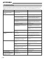
APPENDIX
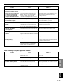
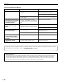
Troubleshooting ......................... 28
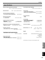
Specifications ............................. 31
CAUTION
OUTLINE OF
THIS UNIT
CONTROLS &
THEIR FUNCTIONS
BASIC
OPERATION
ADVANCED
OPERATION
APPENDIX
English
CONTENTS
*
Manufactured under license from Dolby Laboratories.
“Dolby”, “AC-3”, “Pro Logic” and the double-D symbol are
trademarks of Dolby Laboratories.
Confidential Unpublished Works. 1992–1997 Dolby
Laboratories, Inc. All rights reserved.
**
Manufactured under license from Digital Theater Systems, Inc.
US Pat. No. 5,451,942 and other world-wide patents issued and
pending. “DTS”, “DTS Digital Surround”, are trademarks of Digital
Theater Systems, Inc. Copyright 1996 Digital Theater Systems,
Inc. All Rights Reserved.
LISTENING TO AN FM
BROADCAST
Tuning into an FM station........... 14
Using the presets........................ 16
LISTENING TO AN
FM BROADCAST

E-2
1. To assure the finest performance, please read this
manual carefully. Keep it in a safe place for future
reference.
2. Install this unit in a cool, dry, clean place – away from
windows, heat sources, sources of excessive
vibration, dust, moisture and cold. Avoid sources of
humming (transformers, motors). To prevent fire or
electric shock, do not expose the unit to rain or water.
3. Never open the cabinet. If something drops into the
set, contact your dealer.
4. Do not use force on switches, controls or connection
wires. When moving the unit, first disconnect the
power plug and the wires connected to other
equipment. Never pull the wires themselves.
5. The openings on the unit cover assure proper
ventilation of the unit. If these openings are
obstructed, the temperature inside the unit will rise
rapidly; therefore, avoid placing objects against these
openings. To prevent fire or damage, install the unit in
a well-ventilated area.
<Europe and U.K. models only>
To prevent fire or damage, be sure to allow a space of
at least 10 cm behind, 10 cm on both sides and 10 cm
above the top panel of the unit.
6. The voltage used must be the same as that specified
on this unit. Using this unit with a higher voltage than
specified is dangerous and may result in fire or other
accidents. YAMAHA will not be held responsible for
any damage resulting from use of this unit with a
voltage other than that specified.
7. Always set the volume to minimum before starting
audio playback. Increase the volume gradually to an
appropriate level after playback has been started.
8. Do not attempt to clean the unit with chemical solvents
as this might damage the finish. Use a clean, dry
cloth.
9. Be sure to read the “TROUBLESHOOTING” section
regarding common operating errors before concluding
that the unit is faulty.
10. When not planning to use this unit for a long period
(i.e., vacation, etc.), disconnect the AC power plug
from the wall outlet.
11.
To prevent lightning damage, disconnect the AC power
plug when there is an electric storm.
12. Grounding or polarization – Precautions should be
taken so that the grounding or polarization of
appliances is not defeated.
For U.K. customers
If the socket outlets in the home are not suitable for the
plug supplied with this appliance, it should be cut off and
an appropriate 3 pin plug fitted. For details, refer to the
instructions described below.
Note: The plug severed from the mains lead must be
destroyed, as a plug with bared flexible cord is hazardous if
engaged in a live socket outlet.
SPECIAL INSTRUCTIONS FOR U.K. MODEL
IMPORTANT:
THE WIRES IN MAINS LEAD ARE COLOURED IN
ACCORDANCE WITH THE FOLLOWING CODE:
Blue: NEUTRAL
Brown: LIVE
As the colours of the wires in the mains lead of this
apparatus may not correspond with the coloured
markings identifying the terminals in your plug, proceed
as follows: The wire which is coloured BLUE must be
connected to the terminal which is marked with the
letter N or coloured BLACK. The wire which is coloured
BROWN must be connected to the terminal which is
marked with the letter L or coloured RED. Making sure
that neither core is connected to the earth terminal of
the three pin plug.
For Canadian Customers
To prevent electric shock, match wide blade of plug to
wide slot and fully insert.
This Class B digital apparatus complies with Canadian
ICES-003.
When this unit is turned off by pressing the power switch
on the front panel or the POWER key on the remote
control, this unit turns into the standby mode. In this
mode, this unit is designed to consume a small amount
of power. This unit’s power supply is completely cut off
from the AC line only when the AC power cord is
disconnected.
CAUTION:
Read this before operating this unit

E-3
English
OUTLINE OF THIS UNIT
English
OUTLINE OF
THIS UNIT
PC
AUX1
AUX2
TUNER
DSP P-SET
VOL
VIRTUAL
5.I
CH
DIGITAL
PROLOGIC FM AMST
USB PCM D.
DSP
SUPERWOOFER SYSTEM YST-SW45
HIGH CUTSTANDBY/ON
150Hz50Hz
VOLUME
100
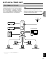
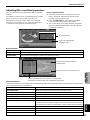
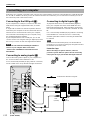
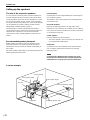
Main features of this unit
Using Yamaha’s unique DSP technology, this unit can bring
excitement and realism to any audio source by simulating
the acoustic environments of concert halls, movie theaters,
and so on. With its stylish, vertical design, this unit allows
you to use various audio sources, including the built-in FM
tuner, your computer, CD player, MD or tape deck, as
shown below.
OUTLINE OF THIS UNIT
Although this unit can be used as part of a typical hi-fi
system, connecting it to your computer via the USB
terminal, and running the supplied Application Software,
allows you to remotely control this unit from your computer
and make some adjustments and settings.
CD player
MD recorder
etc.
This unit
Personal computer
Front speaker (L)
Front speaker (R)
* Refer to the separate “SET UP MANUAL” for
connections.
FM antenna
Subwoofer
Surround speaker (L)
Surround speaker (R)
Center speaker

E-4
OUTLINE OF THIS UNIT
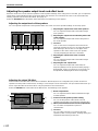
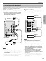
Dolby Digital and DTS
This unit features a built-in Dolby Digital decoder and a DTS decoder for reproducing surround sounds of sources encoded
with Dolby Digital or DTS. With such state-of-the-art technologies, this unit can bring the same audio experience to your
home as they have brought to feature films in quality theaters around the world.
Take some time now to read more about these features and enjoy the new experiences this system brings to your home
theater.
DTS (Digital Theater System)
Digital Surround
DTS was developed to replace the analog soundtracks of
movies with six discrete channels of digital soundtracks,
and it is now installed in many theaters around the world.
The DTS digital playback system changed the way we
experienced movies in theaters with six discrete channels
of superb digital audio. DTS technology, through intense
research and development, has made it possible to deliver
similar encode/decode discrete technology to home audio
surround-sound entertainment. DTS Digital Surround is an
encode/decode system which delivers six channels of
master-quality, 20-bit audio; technically, it offers 5.1
channels, which means 5 full-range (left, center, right and
two surround) channels, plus a subwoofer (LFE) channel
(as “0.1”). It is compatible with the 5.1 speaker
configurations that are currently available for home theater
systems.
Dolby Surround
Dolby Surround uses four discrete channels and five
speakers to reproduce realistic and dynamic sound effects:
two main channels (left and right), a center channel for
dialog, and a surround channel for special sound effects.
The surround channel reproduces sound within a narrow
frequency range.
Most video tapes and laser discs include Dolby Surround
encoding, as do many TV and cable broadcasts. The Dolby
Pro Logic decoder built into this unit employs a digital
signal processing system that stabilizes each channel for
even more accurate sound positioning than is available
with standard analog processors.
Dolby Digital
Dolby Digital is a digital surround sound system that
provides completely independent multi-channel audio to
you. Dolby Digital provides five full-range channels in what
is sometimes referred to as a “3/2” configuration: three front
channels (left, center and right), and two surround
channels. A sixth bass-only effect channel is also provided
for output of LFE (low frequency effect), or low bass effects
that are independent of other channels. (This is called the
“LFE channel”.) This channel is counted as 0.1, thus giving
rise to the term 5.1 channels in total.
The wide dynamic range of sound reproduced by the five
full-range channels and precise sound orientation by digital
sound processing provides listeners with excitement and
realism that have never been experienced before.

E-5
English
OUTLINE OF THIS UNIT
English
OUTLINE OF
THIS UNIT
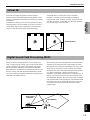
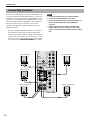
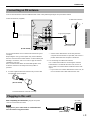
Virtual 3D
FL C FR
RL RR
FL C FR
RL RR
Virtual speakers
Typical surround system Virtual 3D
Early sound
reflections
Reverberation
Direct sound
Surround sound typically requires several speakers
situated in front of and behind the listening position, which
requires a substantial amount of space that may not always
be available.
In addition to ordinary surround sound reproduction using
several speakers, this unit enables you to enjoy surround
sound effects with only two speakers by using Yamaha’s
unique “Virtual 3D” (three-dimensional) technology.
Virtual 3D, which is used by this unit’s sound field
programs, simulates the surround effect provided by
surround and center speakers, creating “virtual” surround
speakers, as shown, so even with only two front speakers,
you can still enjoy surround sound.
Digital Sound Field Processing (DSP)
When you listen to a performance in a concert hall, jazz
club, or other live music venue, you not only hear the direct
sound coming from the musical instruments and singers,
but also the “early reflections” and natural reverberation.
Early reflections are the initial sound waves that bounce off
the floor, ceiling, and walls. Natural reverberation is made
up of sound waves that gradually attenuate as they bounce
repeatedly off multiple surfaces.
Since the way you hear early reflections and reverberation
depends on the shape and size of the building as well as
the material and construction of the walls and ceiling, each
venue has its own unique “sound,” called its “sound field.”
At Yamaha, we have measured all the elements that make
up a typical sound field—direction and level of the
reflections, band-width characteristics, and delay times—at
famous concert halls and opera houses around the world.
The information gained in this process has been converted
into programs that can be reproduced using Yamaha’s DSP
technology. Using its on-board DSP, this unit can process
any audio source and recreate the atmosphere of the
original venue.

E-6
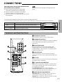
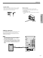
CONTROLS AND THEIR FUNCTIONS
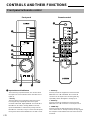
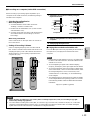
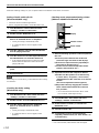
1 Input selectors & indicators
These four keys, explained below, are used to select
the input source. The indicator of the selected source
lights up.
● PC key
This key selects your computer as the input source.
Pressing this key repeatedly selects the signals
received at the USB, digital (DIGITAL PC COAX IN or
DIGITAL PC OPT IN) or analog (ANALOG PC IN)
input. The DIGITAL PC OPT IN has priority over the
DIGITAL PC COAX IN, so if you connect to both inputs,
the signal received at the DIGITAL PC OPT IN is used.
CONTROLS AND THEIR FUNCTIONS
Front panel & Remote control
Front panel
Remote control
PC
AUX1
AUX2
TUNER
DSP P-SET
VOL
VIRTUAL
5.I
CH
DIGITAL
PROLOGIC FM AM ST
USB PCM D.
DSP
1
2
3
4
5
6
7 8
POWER
PC
AUX1
AUX2
TUNER
JAZZ CHURCHHALL
B
VOLUMEMUTE
CA
MOVIE LIVE
PRESET MANUALMEMORY
GAME
TEST
ON
/
OFF
/DTS
SURROUND
8
0
9
4
C
A
B
1
E
D
3
6
● AUX1 key
This key selects the equipment connected to the
ANALOG AUX 1 IN or DIGITAL AUX 1 OPT IN
connector as the input source. Pressing this key
repeatedly selects the digital or analog input.
● AUX2 key
This key selects the equipment connected to the
ANALOG AUX 2 IN connectors as the input source.
● TUNER key
This key selects the built-in FM tuner as the input
source. If the tuner is already selected, this key toggles
the reception mode between FM auto stereo and FM
monaural.

E-7
English
CONTROLS AND THEIR FUNCTIONS
CONTROLS &
THEIR FUNCTIONS
2 Display
The display shows various settings, selected input
source, sound field program and various other
information.
3 DSP key [front panel]
ON/OFF key [remote control]
This key activates the sound field programs produced
by the internal DSP.
4 P-SET key ( ) [front panel]
PRESET key [remote control]
This key changes the display status of the built-in FM
tuner from the frequency display mode to the preset
tuning mode.
If the tuner is already in the preset tuning mode, each
press of this key changes the group of preset stations
(A, B, C, D, E).
* This key works only when the tuner is selected as the
input source.
5 / (Down/Up) keys
These keys are used for selecting sound field
programs, changing station frequencies, selecting
preset station numbers, etc.
6 Volume control [front panel]
VOLUME
(Down/Up) keys [remote control]
These control and keys adjust the speaker and
headphone volume. The volume cannot be adjusted
when this unit is in the standby mode.
7 Headphone jack
Stereo headphones can be connected to this mini-jack
for private listening, with Virtual 3D effects specifically
tailored for headphone listening.
8 Power switch ( ) [front panel]
POWER key [remote control]
Each click of this switch changes the status of this unit
between standby mode and power on.
* In the standby mode, this unit can be turned on
remotely from your computer, using the supplied
Application Software. Note that this unit uses a small
amount of power in the standby mode.
9 MEMORY key
This key is used to store a desired station in the
memory.
* This key works only when the tuner is selected as
the input source.
0 Sound field program selector keys
Each of these keys selects the corresponding sound
field program.
A TEST key
This key is used to output a test tone. The test tone is
used when adjusting the volume balance among all
speakers in the system including the virtual surround
speakers. (Refer to page 19 for details.)
B Custom keys (A, B, C)
These keys are available when this unit and your
computer are connected with the USB cable, and the
supplied Application Software is installed on the
computer.
Each of these keys can be programmed with a set of
commands (input selector, sound field program,
volume setting, etc.) by using the Application Software.
After storing, simply pressing each key will execute the
stored command.
* Refer to the online help of the Application Software for
details.
C MUTE key
This key is used to cut off sound output temporarily.
Turning the volume control on the front panel or
pressing the VOLUME keys on the remote control
restores sound output. Pressing this key again also
restores sound output.
* Sound output will also be restored by changing the
status of this unit between standby and power-on,
changing the input source or the sound field program,
and so on.
D MANUAL key
This key changes the display status of the built-in FM
tuner from the preset tuning mode to the frequency
display mode.
* This key works only when the tuner is selected as the
input source.
E Tuning /
(Down/Up) keys
These keys work in the following ways according to the
status of the tuner.
In the frequency display mode:
Each press of selects a higher frequency and
selects a lower frequency.
In the preset tuning mode:
Each press of selects a higher preset station
number and selects a lower preset station number.

E-8
CONTROLS AND THEIR FUNCTIONS
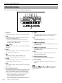
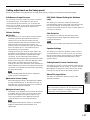
About the display
This section explains what the various display indicators mean.
1 VIRTUAL
This indicator appears when this unit is using Virtual 3D.
2 USB
This indicator appears when audio signals are sent or
received via the USB terminal.
* If you use a Macintosh computer, this indicator is
always illuminated when this unit is connected to the
computer via the USB terminals.
3 (DTS)
This indicator appears when an input signal is decoded
with DTS.
4 PCM
This indicator appears when a PCM digital audio signal
is selected as the input source.
5
This indicator appears when headphones are
connected to the headphone jack of this unit.
6 5.1CH
This indicator appears when a 5.1 channel digital audio
signal is selected as the input source.
7 DSP
This indicator appears when the DSP is processing the
input signal.
8 Sound output indicator
This indicator shows the currently used speakers. A red
dot shows that the corresponding speaker is currently
used, or the speaker is set for use in the Application
Software. The mark shows that sound is outputted.
* When using the test tone, a red dot shows the
channel currently outputting the test tone.
* When using headphones, only the two dots for the left
and right front speakers appear regardless of the
setting in “Speaker Settings”.
9 D.
This indicator appears when an audio signal encoded
with Dolby Digital is selected as the input source.
0 ST
This indicator appears when a stereo broadcast is
received in stereo mode.
A (DOLBY) DIGITAL
This indicator appears when an input signal is decoded
with Dolby Digital.
B (DOLBY) PROLOGIC
This indicator appears when an input signal is decoded
with Dolby ProLogic.
C FM
This indicator appears when the built-in FM tuner is
selected as the input source.
D Multi-information display
Various messages and information appear here.
E VOL (volume)
This indicator graphically displays the volume level
setting.
Note
The indicators , “5.1CH” and will not appear when
sound signals are decoded on the computer (by using DVD-
playback software, etc.).
VOL
VIRTUAL 5.ICH
DIGITAL
PROLOGIC FM ST
USB PCM D.
DSP
1
A
E
3
9
0
6542
B
C
D
8
7

E-9
BASIC OPERATION
English
BASIC
OPERATION
BASIC OPERATION
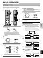
Playing a source
4
Start the selected input source.
Refer to “Listening to an FM broadcast” on pages 14–18
about how to tune into a desired station.
5
Adjust the volume to the desired level.
6
As you prefer, use a sound field program.
Refer to page 11 for details about the sound field programs.
About the input selector keys
Each of the input selector keys selects the following input signals.
PC: Press the PC key repeatedly to select the PC inputs:
“USB”, “PC_DIGT” and “PC_ANLG”. PC_DIGT selects
the DIGITAL PC COAX IN or DIGITAL PC OPT IN, and
PC_ANLG selects the ANALOG PC IN.
Note: The DIGITAL PC OPT IN has priority over the
DIGITAL PC COAX IN, so if you connect to both inputs,
the signal received at the DIGITAL PC OPT IN is used.
AUX1: Press the AUX1 key repeatedly to select the inputs:
“AUX1_DG” and “AUX1_AN”. AUX1_DG selects the
equipment connected to the DIGITAL AUX 1 OPT IN, and
AUX1_AN selects the equipment connected to the
ANALOG AUX 1 IN connector as the input source.
AUX2: Press the AUX2 key to select
the equipment connected to
the ANALOG AUX 2 IN
connectors as the input
source.
TUNER: Press the TUNER key to select the built-in FM tuner as
the input source.
* When the TUNER key is pressed, “TUNER” appears
first on the display, and then changes to the display of
a frequency or a preset station.
This section explains how to turn on this unit and select
input sources. If any external audio equipment is
connected to this unit, turn it on first.
1
Turn on this unit.
The message “Hello” appears for a few seconds, and this
unit returns to the state in which it was last used (e.g., the
input source that was selected when this unit was turned off
is selected).
2
Decrease the volume to minimum (MIN).
3
Select an input source by using the input selector
keys.
The corresponding indicator on the front panel lights up.
Refer to the explanation on the right side for details about
using the input selector keys.
PC
AUX1
AUX2
TUNER
DSP P-SET
VOL
VIRTUAL
5.I
CH
DIGITAL
PROLOGIC FM AMST
USB PCM D.
DSP
PC
AUX1
AUX2
TUNER
JAZZ CHURCHHALL
B CA
MOVIE LIVE
PRESET MANUALMEMORY
GAME
TEST
ON
/
OFF
/DTS
SURROUND
VOLUMEMUTE
POWER
3
2, 5
1
3
2, 5
1
POWER
Front panel
or
Remote control
VOLUME
Front panel
or
Remote control
TUNER
PC
AUX1
AUX2
TUNER
PC
AUX1
AUX2
Front panel
or
Remote control
VOLUME
Front panel
or
Remote control
VOLVOL
VOL
VOL
VOL
VOL
VOL
FM ST
VOL
FM ST

E-10
BASIC OPERATION
Note
When the PC, AUX1 or AUX2 input selector key is pressed, the
display shows the name of the selected input source for a short
while, and then shows the currently selected sound field
program.
When no sound field program is selected, “THROUGH” is
shown on the display.
The names of input sources shown on the display can be changed
with the Application Software. Refer to the Online Help of the
Application Software for details.
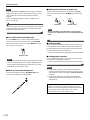
To cut off sound output temporarily
Press the MUTE key. To restore sound output, turn the
volume control on the front panel or press the VOLUME
keys on the remote control. Pressing the MUTE key again
also restores sound output.
Note
Sound output will also be restored by changing the status of this
unit between standby and power-on modes, changing the input
source or the sound field program, using the test tone, or using
the A, B, C keys on the remote control.
When you listen with headphones
Connect the headphones to the headphone jack. No
sound will be outputted from the speakers.
When you have finished using this unit
Set this unit to the standby mode by pressing the power
switch on the front panel or the POWER key on the remote
control.
Note
When not planning to use this unit for a long period (i.e.,
vacation, etc.), disconnect the AC power plug from the wall
outlet.
Setting USB MIX
When an input other than the USB terminal is selected, you
can listen to the mixed signals from the selected input and
from the USB terminal. Also, the mixing ratio of the signals
from the USB terminal can be adjusted.
* Refer to the online help of the Application Software for details.
Setting graphic equalizer
You can adjust the frequency characteristics as you prefer
by using the 7-band graphic equalizer.
* Refer to the online help of the Application Software for details.
Notes
● Some setting changes may be needed on the computer to
reproduce signals sent from the computer to this unit via the
USB connection. Refer to the separate “SET UP MANUAL”
for details.
● Some setting changes may be needed on the computer to
reproduce signals sent from the computer to this unit via a
sound card, etc.
Automatic power saving function
If there is no operation on this unit’s front panel, the
remote control or the Application Software for about 24
hours with the power of this unit on, this unit will
automatically be set to the standby mode.
MUTE
Remote control
POWER
Front panel
or
Remote control

E-11
BASIC OPERATION
English
BASIC
OPERATION
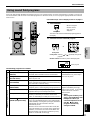
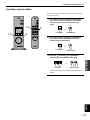
Using sound field programs
This unit’s built-in DSP (Digital Sound field Processor) can simulate various acoustic environments, including a concert hall
and movie theater, with its seven sound field programs. For the best results, choose a program appropriate for the selected
audio source.
First follow steps 1–5 of “Playing a source” on page 9.
1
Turn on the DSP.
(When using the
remote control,
step 1 can be
skipped.)
The name of the selected sound field program appears on
the display.
2
Select the desired sound field program.
Front panel: Pressing or repeatedly changes the
program.
Remote control: Press the key of the desired program.
The following programs are available.
PC
AUX1
AUX2
TUNER
DSP P-SET
VOL
VIRTUAL
5.I
CH
DIGITAL
PROLOGIC FM AMST
USB PCM D.
DSP
PC
AUX1
AUX2
TUNER
JAZZ CHURCHHALL
B CA
MOVIE LIVE
PRESET MANUALMEMORY
GAME
TEST
ON
/
OFF
/DTS
SURROUND
VOLUMEMUTE
POWER
21
2
DSP
Front panel
JAZZ CHURCHHALL
MOVIE LIVEGAME
TEST
ON
/
OFF
/DTS
SURROUND
Front panel
or
Remote control
VOL
DSP
Active program
Program
HALL (CONCERT HALL
EUROPE)
JAZZ (JAZZ CLUB
VILLAGE GATE)
CHURCH (CHURCH
ROYAUMONT)
GAME (GAME
AMUSEMENT)
MOVIE (MOVIE THEATER)
LIVE (LIVE CONCERT)
NORMAL ( DTS SUR.)
[HP3D*
(Headphone 3D)
]
Feature
This program simulates the sound field of a medium-
sized hall, with a beautiful and rich reverberation.
This program simulates the sound field of a famous
New York jazz club.
This program simulates the sound field of a Gothic
church, with the unique effect of sound reverberating
back and forth in a domed ceiling.
This program adds depth and surround effects to
computer games, enhancing the gaming experience.
The realism provided by this program gives the
impression that you’re actually in the scene.
This program produces an enthusiastic atmosphere
and lets you feel that you are in the midst of the
action, as if attending an actual jazz or rock concert.
This program reproduces the surround sound of a
source encoded with Dolby Pro Logic, Dolby Digital
or DTS faithfully. Sensing the input signal, the built-in
Dolby Digital decoder or the DTS decoder
automatically works.
When this unit is set to the “Virtual 3D” mode (the
surround speakers are not used) in the Application
Software, 5.1-channel surround sound effects are
reproduced with only two front speakers by using
Yamaha’s “Virtual 3D” technology.
Note
These programs create a sound
field that feels real, just as if you
were actually there.
These programs can be used
together with Dolby Pro Logic,
Dolby Digital or DTS for enjoying
surround sounds of motion-
picture audio.
*
: HP3D
This program enables you to
enjoy a virtual 3D effect with
headphones. When you
connect headphones to this
unit, the DTS SUR.
program automatically
changes to HP3D .
Hi-Fi DSP (for music sources)
CINEMA DSP (for video sources)

E-12
BASIC OPERATION
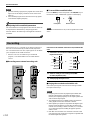
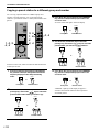
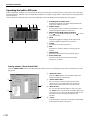
First turn on the external unit to be used, and then this
unit.
1
Select the source to be recorded by using the
input selector keys.
2
Start recording on a recording unit (an MD
recorder, tape deck, etc.).
3
Start playing the input source .
Playing the recorded result via this unit
Select the input signals sent from the recording unit with
the input selector keys.
Notes
● If input signals received at any digital input terminal other
than the USB terminal is outputted at the digital output
terminal, the sampling frequency for the output signals is the
same as that for input signals.
● The sampling frequency for digital signals converted from
analog signals on this unit is 44.1 kHz or 48 kHz.
● When digital input signals are outputted at the digital output
terminal, track information (CD-text data, automatic track
renewal when recording is made on an MD, etc.) is invalid if
any sound field program (including the graphic equalizer
effect) is used.
● Both REC OUT and OPT OUT terminals on the rear of this
unit output the same constituents of signals as outputted from
the left and right front speakers.
Recording
Input sources (e.g., a computer or CD player) selected on
this unit can be recorded by an MD recorder, tape deck,
etc. connected to this unit. Also, input signals can be fed to
your computer via the USB connection.
* When a source is recorded using a sound field
program, sound field effects are recorded with the
source.
Recording on an external recording unit
PC
AUX1
AUX2
TUNER
DSP P-SET
VOL
VIRTUAL
5.I
CH
DIGITAL
PROLOGIC FM AMST
USB PCM D.
DSP
PC
AUX1
AUX2
TUNER
JAZZ CHURCHHALL
B CA
MOVIE LIVE
PRESET MANUALMEMORY
GAME
TEST
ON
/
OFF
/DTS
SURROUND
VOLUMEMUTE
POWER
1
1
TUNER
PC
AUX1
AUX2
TUNER
PC
AUX1
AUX2
Front panel
or
Remote control
Notes
● Just after selecting a program, the program name scrolls from
right to left on the display, and then its short-version name
lights up.
● No sound field program can be used when receiving signals
with a 96 kHz sampling frequency.
ON
/
OFF
DSP
Front panel
or
Remote control
To turn off the sound field effect
Press the DSP key on the front panel or the ON/OFF key on
the remote control. “THROUGH” appears on the display.
Note
When the sound field effect is off, sound is reproduced in normal
stereo.
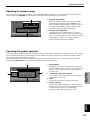
Adjusting DSP sound field parameters
The surround effect of each program or the Virtual 3D effect can
be adjusted to the desired taste by using the Application
Software. Refer to the online help of the Application Software
for details.

E-13
BASIC OPERATION
English
BASIC
OPERATION
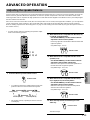
Recording on a computer (via the USB connection)
1
Select the source to be recorded by using the
input selector keys.
2
Start recording with the recording software on the
computer.
3
Start playing the input source.
Playing the recorded result via this unit
Press the PC input selector key repeatedly to select USB as
the input source, and play the recorded result on the
computer.
Notes
● If the number of USB channels is set to six, recording cannot
be made via the USB connection. Reset the number of USB
channels to two or four.
● To record digital input signals with a 48 kHz sampling
frequency, the frequency of the input signals must be 48 kHz.
● To record sound signals received at an analog or digital input
of the sound card etc., and not via the USB connection, select
the corresponding device, such as “Sound Card”, from
“Preferred device” of “Recording” (or “Sound Recording”)
on the computer.
● The sampling frequency and resolution of signals recordable
on the computer differ from operating systems. You can refer
to the following Yamaha website for details about the related
information.
http://www.yamaha.co.jp/audio/
TUNER
PC
AUX1
AUX2
TUNER
PC
AUX1
AUX2
Front panel
or
Remote control
PC
AUX1
AUX2
TUNER
DSP P-SET
VOL
VIRTUAL
5.I
CH
DIGITAL
PROLOGIC FM AMST
USB PCM D.
DSP
PC
AUX1
AUX2
TUNER
JAZZ CHURCHHALL
B CA
MOVIE LIVE
PRESET MANUALMEMORY
GAME
TEST
ON
/
OFF
/DTS
SURROUND
VOLUMEMUTE
POWER
1
1
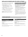
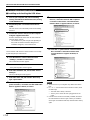
When recording or processing signals inputted to your
computer via the USB connection, the following setting is
needed on the computer.
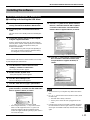
Selecting Recording Device
When using Windows
1. Click the Windows “Start” button and select
“Settings”, and then “Control Panel”.
2. Double-click the “Multimedia” icon (or the “Sounds
and Multimedia” icon).
3. Click the “Audio” tab and select “USB Audio Device”
at “Preferred device” of “Recording” (or “Sound
Recording”).
When using a Macintosh
Select “USB Audio” as the input device at “Sound” on
the Control Panel.
Setting of Recording Software
Select a sampling frequency from 44.1 kHz and 48
kHz. Select a resolution from 16 bits and 24 bits. The
sampling frequency of 44.1 kHz with the resolution of
16 bits produces a sound quality comparable to the
compact disc (CD).
Notes
● Please check the copyright laws in your country before recording compact discs, radio, etc. Recording of copyright
material may infringe copyright laws.
● You cannot make a recording from a CD-R, MD, etc. which is a copy of an audio CD, to another CD-R, MD, etc. via the USB
connection or the digital terminal connection. Also, you cannot make a recording from an MD which is recorded with digital
signals received via the USB connection, to another MD via a digital connection.

E-14
LISTENING TO AN FM BROADCAST
LISTENING TO AN FM BROADCAST
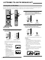
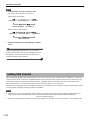
Tuning into an FM station
Normally, if station signals are strong and there is no interference, quick auto tuning is possible. However, if the signal of the
station you want to select is weak or the reception condition is bad, you must tune in to it manually.
Auto tuning
First turn on this unit.
1
Press the TUNER input selector key to select the
built-in FM tuner.
The tuner turns on in either of the following modes. (The
mode which was selected the last time you used the tuner is
selected.)
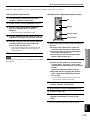
● Frequency display mode
The display shows the
selected frequency. This
mode is for tuning into a
station by changing the
frequency.
● Preset tuning mode
This mode is for tuning into a
preset station which is
already stored in the memory.
The display shows the preset
group (A to E), the number (1
to 8) and the frequency of the
preset station.
2
If the tuner is in the preset tuning mode, press the
TUNER key (front panel) or the MANUAL key
(remote control) to change the preset tuning mode
to the frequency display mode.
3
Press the TUNER key (front panel) or the MANUAL
key (remote control) to select the desired
reception mode: FM auto stereo or FM monaural.
The reception mode changes alternately by each press of the
TUNER key.
● FM auto stereo
When a stereo broadcast is received, it is received in
stereo automatically. (The “ST” indicator lights up on
the display.) If, however, the signal of a stereo
broadcast is weak, it may be received in monaural
automatically. (In this case, the “ST” indicator goes
off.)
● FM monaural
Any broadcast is received in monaural. (On the display,
“M” appears above the frequency.) If you hear noise in
the FM auto stereo mode, try switching to FM
monaural.
PC
AUX1
AUX2
TUNER
DSP P-SET
VOL
VIRTUAL
5.I
CH
DIGITAL
PROLOGIC FM AMST
USB PCM D.
DSP
PC
AUX1
AUX2
TUNER
JAZZ CHURCHHALL
B CA
MOVIE LIVE
PRESET MANUALMEMORY
GAME
TEST
ON
/
OFF
/DTS
SURROUND
VOLUMEMUTE
POWER
1, 2,
3
1
2,
3
4
4
TUNER
PC
AUX1
AUX2
TUNER
PC
AUX1
AUX2
Front panel
or
Remote control
VOL
FM ST
VOL
FM ST
TUNER
PC
AUX1
AUX2
MANUAL
Front panel
or
Remote control
VOL
FM ST
VOL
FM
FM auto stereo
FM monaural
TUNER
PC
AUX1
AUX2
MANUAL
Front panel
or
Remote control
(U.S.A. model)

E-15
LISTENING TO AN FM BROADCAST
English
LISTENING TO AN
FM BROADCAST
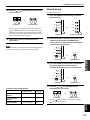
4
Press the or key and keep it pressed for one
second or more.
Press the key to search for lower frequencies and the
key for higher frequencies. When a station with a strong
signal is found, the search stops and the station is received.
If no station with a strong signal is found, the search stops
after searching through all frequencies.
5
If the received station is not the desired one,
repeat step 4.
Note
If the desired station cannot be found by the auto tuning method,
search for the station by using the manual tuning method.
Manual tuning
First turn on this unit.
1
Press the TUNER input selector key to select the
built-in FM tuner.
2
If the tuner is in the preset tuning mode, press the
TUNER key (front panel) or the MANUAL key
(remote control) to change the preset tuning mode
to the frequency display mode.
3
Press the TUNER key (front panel) or the MANUAL
key (remote control) to select the desired
reception mode: FM auto stereo or FM monaural.
4
Press the or key repeatedly until the
desired frequency is located.
Press the key to search for lower frequencies and the
key for higher frequencies.
Front panel
or
Remote control
TUNER
PC
AUX1
AUX2
TUNER
PC
AUX1
AUX2
Front panel
or
Remote control
TUNER
PC
AUX1
AUX2
MANUAL
Front panel
or
Remote control
Front panel
or
Remote control
Frequency range and tuning step
Frequency range
Tuning step
U.S.A. and Canada
models
87.50–107.90 MHz 0.20
U.K. and Europe
models
87.50–108.00 MHz 0.05
Australia model 87.50–108.00 MHz 0.10
TUNER
PC
AUX1
AUX2
MANUAL
Front panel
or
Remote control

E-16
LISTENING TO AN FM BROADCAST
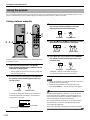
Using the presets
You can store your favorite stations in the 40 presets, which are organized into five groups (A–B), with eight presets in each
group. A stored station can be recalled simply by selecting the preset number in which it is stored.
Storing stations manually
First turn on this unit, and then select the built-in FM tuner
as the input source.
1
In the frequency display mode, tune into the
desired station and select the reception mode: FM
auto stereo or FM monaural.
* Refer to pages 14 to 15 on how to tune into a station and
select the reception mode.
2
Press the P-SET key (front panel) or the MEMORY
key (remote control) and keep it pressed for one
second or more.
A preset group and a preset number appears and an arrow
scrolls from right to left on the display. This means that
storing a station is possible.
3
Press the P-SET key (front panel) or the PRESET
key (remote control) repeatedly to select the
desired preset group from A through E.
4
Press the key or the key repeatedly to select
the desired preset number from 1 through 8.
5
Press the P-SET key (front panel) or the MEMORY
key (remote control) and keep it pressed for one
second or more.
“MEMORY” lights up on the display for approx. 2
seconds to show that the station has been stored.
Notes
● A newly stored station overwrites the previously stored one in
the same preset group and number.
● To abort storing the station, press an input selector key
(except the TUNER key). The selected input mode appears.
With the supplied Application Software, you can use the auto
preset tuning function in addition to the manual method. The
auto preset function searches for all stations available in your
area and automatically stores them in the presets.
Also, the Application Software allows you to assign a name to
each preset station. The names are displayed on the monitor
when running the Application.
Refer to the online help of the Application Software for details.
Front panel
or
Remote control
PC
AUX1
AUX2
TUNER
DSP P-SET
VOL
VIRTUAL
5.I
CH
DIGITAL
PROLOGIC FM AMST
USB PCM D.
DSP
PC
AUX1
AUX2
TUNER
JAZZ CHURCHHALL
B CA
MOVIE LIVE
PRESET MANUALMEMORY
GAME
TEST
ON
/
OFF
/DTS
SURROUND
VOLUMEMUTE
POWER
2, 5
2, 3, 5 4
4
3
MEMORY
P-SET
Front panel
or
Remote control
VOL
FM ST
Preset numberPreset group
PRESET
P-SET
Front panel
or
Remote control
MEMORY
P-SET
Front panel
or
Remote control
(U.S.A. model)
A página está carregando...
A página está carregando...
A página está carregando...
A página está carregando...
A página está carregando...
A página está carregando...
A página está carregando...
A página está carregando...
A página está carregando...
A página está carregando...
A página está carregando...
A página está carregando...
A página está carregando...
A página está carregando...
A página está carregando...
A página está carregando...
A página está carregando...
A página está carregando...
A página está carregando...
A página está carregando...
A página está carregando...
A página está carregando...
A página está carregando...
A página está carregando...
A página está carregando...
A página está carregando...
A página está carregando...
A página está carregando...
A página está carregando...
A página está carregando...
A página está carregando...
A página está carregando...
A página está carregando...
A página está carregando...
A página está carregando...
A página está carregando...
A página está carregando...
-
 1
1
-
 2
2
-
 3
3
-
 4
4
-
 5
5
-
 6
6
-
 7
7
-
 8
8
-
 9
9
-
 10
10
-
 11
11
-
 12
12
-
 13
13
-
 14
14
-
 15
15
-
 16
16
-
 17
17
-
 18
18
-
 19
19
-
 20
20
-
 21
21
-
 22
22
-
 23
23
-
 24
24
-
 25
25
-
 26
26
-
 27
27
-
 28
28
-
 29
29
-
 30
30
-
 31
31
-
 32
32
-
 33
33
-
 34
34
-
 35
35
-
 36
36
-
 37
37
-
 38
38
-
 39
39
-
 40
40
-
 41
41
-
 42
42
-
 43
43
-
 44
44
-
 45
45
-
 46
46
-
 47
47
-
 48
48
-
 49
49
-
 50
50
-
 51
51
-
 52
52
-
 53
53
-
 54
54
-
 55
55
-
 56
56
-
 57
57


Tamaha RP-U200 Manual do usuário
- Categoria
- Receptor
- Tipo
- Manual do usuário
em outras línguas
- español: Tamaha RP-U200 Manual de usuario
- français: Tamaha RP-U200 Manuel utilisateur
- italiano: Tamaha RP-U200 Manuale utente
- English: Tamaha RP-U200 User manual
- русский: Tamaha RP-U200 Руководство пользователя
- Nederlands: Tamaha RP-U200 Handleiding
- Deutsch: Tamaha RP-U200 Benutzerhandbuch
- dansk: Tamaha RP-U200 Brugermanual
- čeština: Tamaha RP-U200 Uživatelský manuál
- svenska: Tamaha RP-U200 Användarmanual
- polski: Tamaha RP-U200 Instrukcja obsługi
- Türkçe: Tamaha RP-U200 Kullanım kılavuzu
- suomi: Tamaha RP-U200 Ohjekirja
- română: Tamaha RP-U200 Manual de utilizare
Outros documentos
-
Yamaha DP-U50 Manual do proprietário
-
-
-
-
Yamaha Digital Sound Projector YSP-3000 Manual do proprietário
-
Yamaha YSP-4000 Manual do proprietário
-
-
-
Yamaha YSP-5100 Manual do usuário
-
Yamaha HTR-6280 Manual do proprietário