
INSTRUCTION MANUAL
WWW.NEOMOUNTS.COM
PLASMA-W2500BLACK/SILVER
PLASMA-M2500(T)BLACK/SILVER
PLASMA-W2250BLACK/SILVER
PLASMA-M2250BLACK/SILVER
EN
NL
DE
FR
IT
ES
PT
DK
NO
SE
FI
PL
CS
SK
RO
Floor stand
Vloersteun
Bodenständer
Support au sol
Supporto da pavimento
Soporte de suelo
Suporte de chão
Gulvstander
Gulv stativ
Golvstativ
Lattiateline
Stojak podłogowy
Podlahový stojan
Podlahový stojan
Stativ pentru podea
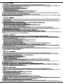
min 1145 mm - max 1645 mm
min 1481 mm - max 1981 mm
min 1030 mm - max 1530 mm
1035 mm
735 mm
900 mm
1035 mm
890 mm
420 mm
100 mm
165 mm
440 mm
735 mm
640 mm
min 1440 mm - max 1940 mm
min 1120 mm - max 1620 mm
min 1190 mm - max 1690 mm

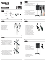
Connect the trolley (E) to the column (D)
Monteer de trolley (E) aan de kolom (D)
Verbinden Sie Fahrgestell (E) und Pylone (D)
Fixez le socle à roulettes (E) à la colonne (D)
Collegare il carrello (E) alla colonna (D)
Conecte el carro (E) a la columna (D)
Encaixe o carrinho (E) à coluna (D)
Podłączyć podstawę wózka (E) do kolumny (D)
Attach upper bar (A) with slotted holes facing upwards and towards the screen.
Attach lower bar (B) with slotted holes facing oor and towards the screen
Bevestig de bovenstang (A) met de sleuven naar boven en richting het scherm.
Bevestig de onderstang (B) met de sleuven naar de vloer en richting het scherm
Obere Stange (A) befestigen mit Langlöcher nach oben und zum Bildschirm. Untere
Stange (B) befestigen mit Langlöcher nach unten und zum Bildschirm
Fixez la barre horizontale supérieure (A) avec les trous oblongs orientés vers le
haut et vers l’écran. Fixez la barre horizontale inférieure (B) avec les trous oblongs
orientés vers le sol et vers l’écran
Attaccare la barra superiore (A) con fori asolati rivolti verso l’alto e verso lo schermo.
Attaccare la barra inferiore (B) con fori asolati rivolti verso il pavimento e verso lo
schermo
Coloque la barra superior (A) con ori cios ranurados hacia arriba y hacia la pantalla.
Coloque la barra inferior (B) con ori cios ranurados hacia el piso y hacia la pantalla
Conecte a barra superior (A) com orifícios voltados para cima e para a tela. Conecte
a barra inferior (B) com orifícios voltados para o chão e para a tela
Przymocuj górną bęlke uchwytu (A) z otworami do góry i w kierunku ekranu.
Przymocuj dolny bęlke uchwytu (B) z otworami skierowanymi w stronę podłogi i
w kierunku ekranu
Connect the 5-pole plug of the control unit (L) with the column. Connect
the power cable (K) with column and socket
Verbind de 5-polige stekker van de afstandsbediening (L) met de kolom.
Verbind de stroomkabel (K) met de kolom en het stopcontact
Verbinden Sie den 5-poligen Stecker der Bedieneinheit (L) mit der Säule.
Verbinden Sie den Stomkabel (K) mit der Säule und der Steckdose
Connecter la prise à 5 pôles de la télécommande (L) sur la colonne.
Branchez le câble d’alimentation (K) sur la colonne
Collegare la spina a 5 poli dell’unità di controllo (L) con la colonna.
Collegare il cavo di alimentazione (K) con la colonna e la presa
Conecte el enchufe de 5 polos de la unidad de control (L) con la columna.
Conecte el cable de alimentación (K) con la columna y el zócalo
Conecte o plugue de 5 pólos da unidade de controle (L) com a coluna.
Conecte o cabo de alimentação (K) com coluna e soquete
Podłącz 5-biegunową wtyczkę sterownika (L) do kolumny. Podłącz
kabel zasilający (K) kolumnę do gniazdka prądowego
For moving the unit up or down just press and keep pressed the buttons
on the control unit (L)
Om het scherm omhoog en omlaag te bewegen houd je de knoppen op
de afstandsbediening (L) ingedrukt
Die Höhenverstellung der Säule erfolgt, indem Sie die Tasten an der
Bedieneinheit (L) drucken und gedrückt halten
Pour incliner l’écran vers le haut ou vers le bas, appuyez et maintenez
enfoncé les boutons de la télécommande (L) jusqu’à la position désirée
Per spostare l’unità verso l’alto o verso il basso basta premere e tenere
premuti i pulsanti sull’unità di controllo (L)
Para mover la unidad hacia arriba o hacia abajo simplemente presione y
mantenga presionados los botones en la unidad de control (L)
Para mover a unidade para cima ou para baixo, basta pressionar e
manter pressionado os botões na unidade de controle (L)
Aby przesunąć urządzenie w górę lub w dół, wystarczy nacisnąć i
przytrzymać przyciski na sterowniku (L)
EN
NL
DE
FR
IT
ES
PT
PL
EN
NL
DE
FR
IT
ES
PT
PL
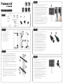
PARTS
EN
NL
DE
FR
IT
ES
PT
PL
EN
NL
DE
FR
IT
ES
PT
PL
EN
NL
DE
FR
IT
ES
PT
PL
PLASMA-M2250BLACK/SILVER
STEP 1
STEP 2
STEP 3
STEP 4
STEP 5
H
E
A
B
F
C
LK
G
D
DL
Tool
Pencil Drill Tape measure
0-130 kg |
0-286,6 lbs
200x200 -
800x600 mm
120-170 cm
Attach the “lift&lock”-brackets (C) to the display (I/J), before attaching them to
the mount and secure the bracket with the “lift&lock” system
Bevestig de de twee verticale “lift&lock”-steunen (C) aan het scherm (I/J), hang
vervolgens aan het frame en vergrendel de steun met het “lift&lock”-systeem
Einhängeschienen (C) am Display befestigen (I/J), bevor diese eingehängt
werden und befestigen Sie die Halterung mit dem “Lift & Lock”-System
Fixez les 2 barres verticales “lift & lock” (C) à l’écran (I/J) avant de les xer sur
les barres horizontales et xez le support avec le système “lift & lock”
Fissare “lift & lock”-staffe (C) al display (I/J), prima di ssare il supporto e
ssare la staffa con il sistema “lift & lock”
Asegure los sujetadores de “levantar y bloquear” (C) a la pantalla (I/J), antes de
colocar el soporte y asegure el soporte con el sistema “levantar y bloquear”
Fixe “levante e bloqueie” - encaixe (C) no visor (I/J), antes de colocar o suporte
e prenda o suporte com o sistema “levante e bloqueie”
Zamontuj ramiona uchwytu (C) do ekranu (I/J), a następnie do belek nośnych
na wózku i zabezpiecz ramiona uchwytu poprzez system “lift&lock”
C. “Lift&Lock”-brackets (x2)
A. Upper bar (x1)
B. Lower bar (x1)
D. Motorised
column (x1)
E. Trolley (x1)
F. M8x40mm (x4)
G. M8x85mm (x2)
I. M8x16mm (x4)
H. M6x30mm (x2)
J. M6x16mm (x4)
L. Control unit (x1) M. Cable clip (x3)K. Power cable (x1)

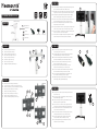
Connect the trolley (D) to the column (C)
Monteer de trolley (D) aan de kolom (C)
Verbinden Sie Fahrgestell (D) und Pylone (C)
Fixez le socle à roulettes (D) à la colonne (C)
Collegare il carrello (D) alla colonna (C)
Conecte el carro (D) a la columna (C)
Encaixe o carrinho (D) à coluna (C)
Podłączyć podstawę wózka (D) do kolumny (C)
Assemble and install the frame (A) to the column (C)
Zet het frame in elkaar en installeer het frame (A) aan de kolom (C)
Montieren Sie den Rahmen (A) und verbinden Sie Rahmen un Säule (C)
Assemblez et installez le cadre (A) sur la colonne (C)
Installare la piastra VESA (A) alla colonna (C)
Montar y instalar la placa VESA (A) a la columna (C)
Montar e instalar a placa VESA (A) na coluna (C)
Zamontuj i Instalowanie płytę VESA (A) w kolumnie (C)
EN
NL
DE
FR
IT
ES
PT
PL
EN
NL
DE
FR
IT
ES
PT
PL
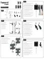
PARTS
PLASMA-M2500BLACK/SILVER
STEP 1
STEP 1
D
A
F
F
/
/
G
G
E
Front view
E
C
Back view
EC
Tool
Pencil Drill Tape measure
0-150 kg |
0-330,7 lbs
200x200 -
800x600 mm
111-161 cm
B. “Lift&Lock”-brackets (x2)
A. Frame (x1)
C. Motorised
column (x1)
D. Trolley (x1)
Connect the 5-pole plug of the control unit (K) with the column. Connect
the power cable (J) with column and socket
Verbind de 5-polige stekker van de afstandsbediening (K) met de kolom.
Verbind de stroomkabel (J) met de kolom en het stopcontact
Verbinden Sie den 5-poligen Stecker der Bedieneinheit (K) mit der Säule.
Verbinden Sie den Stomkabel (J) mit der Säule und der Steckdose
Connecter la prise à 5 pôles de la télécommande (K) sur la colonne.
Branchez le câble d’alimentation (J) sur la colonne
Collegare la spina a 5 poli dell’unità di controllo (K) con la colonna.
Collegare il cavo di alimentazione (J) con la colonna e la presa
Conecte el enchufe de 5 polos de la unidad de control (K) con la columna.
Conecte el cable de alimentación (J) con la columna y el zócalo
Conecte o plugue de 5 pólos da unidade de controle (K) com a coluna.
Conecte o cabo de alimentação (J) com coluna e soquete
Podłącz 5-biegunową wtyczkę sterownika (K) do kolumny. Podłącz
kabel zasilający (J) kolumnę do gniazdka prądowego
For moving the unit up or down just press and keep pressed the buttons
on the control unit (K)
Om het scherm omhoog en omlaag te bewegen houd je de knoppen op
de afstandsbediening (K) ingedrukt
Die Höhenverstellung der Säule erfolgt, indem Sie die Tasten an der
Bedieneinheit (K) drucken und gedrückt halten
Pour incliner l’écran vers le haut ou vers le bas, appuyez et maintenez
enfoncé les boutons de la télécommande (K) jusqu’à la position désirée
Per spostare l’unità verso l’alto o verso il basso basta premere e tenere
premuti i pulsanti sull’unità di controllo (K)
Para mover la unidad hacia arriba o hacia abajo simplemente presione y
mantenga presionados los botones en la unidad de control (K)
Para mover a unidade para cima ou para baixo, basta pressionar e
manter pressionado os botões na unidade de controle (K)
Aby przesunąć urządzenie w górę lub w dół, wystarczy nacisnąć i
przytrzymać przyciski na sterowniku (K)
EN
NL
DE
FR
IT
ES
PT
PL
EN
NL
DE
FR
IT
ES
PT
PL
EN
NL
DE
FR
IT
ES
PT
PL
STEP 3
STEP 4
STEP 5
B
K J
K
Attach the “lift&lock”-brackets (B) to the display (H/I), before attaching them to
the mount and secure the bracket with the “lift&lock” system
Bevestig de de twee verticale “lift&lock”-steunen (B) aan het scherm (H/I), hang
vervolgens aan het frame en vergrendel de steun met het “lift&lock”-systeem
Einhängeschienen (B) am Display befestigen (H/I), bevor diese eingehängt
werden und befestigen Sie die Halterung mit dem “Lift & Lock”-System
Fixez les 2 barres verticales “lift & lock” (B) à l’écran (H/I) avant de les xer sur
les barres horizontales et xez le support avec le système “lift & lock”
Fissare “lift & lock”-staffe (B) al display (H/I), prima di ssare il supporto e
ssare la staffa con il sistema “lift & lock”
Asegure los sujetadores de “levantar y bloquear” (B) a la pantalla (H/I), antes de
colocar el soporte y asegure el soporte con el sistema “levantar y bloquear”
Fixe “levante e bloqueie” - encaixe (B) no visor (H/I), antes de colocar o suporte
e prenda o suporte com o sistema “levante e bloqueie”
Zamontuj ramiona uchwytu (B) do ekranu (H/I), a następnie do belek nośnych
na wózku i zabezpiecz ramiona uchwytu poprzez system “lift&lock”
STEP 2
E. M8x40mm (x8)
F. M8x75mm (x4)
H. M8x16mm (x4)
G. M8 (x4)
I. M6x16mm (x4)
K. Control unit (x1) L. Cable clip (x3)J. Power cable (x1)

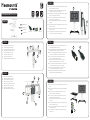
Connect the trolley (D) to the column (C)
Monteer de trolley (D) aan de kolom (C)
Verbinden Sie Fahrgestell (D) und Pylone (C)
Fixez le socle à roulettes (D) à la colonne (C)
Collegare il carrello (D) alla colonna (C)
Conecte el carro (D) a la columna (C)
Encaixe o carrinho (D) à coluna (C)
Podłączyć podstawę wózka (D) do kolumny (C)
Install the frame (A) to the column (C)
Installeer het frame (A) aan de kolom (C)
Verbinden Sie Rahmen (A) un Säule (C)
Installez le cadre (A) sur la colonne (C)
Installare la piastra VESA (A) alla colonna (C)
Instalar la placa VESA (A) a la columna (C)
Instalar a placa VESA (A) na coluna (C)
Instalowanie płytę VESA (A) w kolumnie (C)
EN
NL
DE
FR
IT
ES
PT
PL
EN
NL
DE
FR
IT
ES
PT
PL
PARTS
PLASMA-M2500TBLACK/SILVER
STEP 1
STEP 1
D
F
E
A
C
C
Tool
Pencil Drill Tape measure
0-150 kg |
0-330,7 lbs
200x200 -
800x600 mm
Vert. 89-139 cm
Hor. 95-145 cm
B. Vertical brackets (x2)
A. Tiltable
frame (x1)
C. Motorised
column (x1)
D. Trolley (x1)
STEP 2
Connect the 5-pole plug of the control unit (J) with the column. Connect
the power cable (I) with column and socket
Verbind de 5-polige stekker van de afstandsbediening (J) met de kolom.
Verbind de stroomkabel (I) met de kolom en het stopcontact
Verbinden Sie den 5-poligen Stecker der Bedieneinheit (J) mit der Säule.
Verbinden Sie den Stomkabel (I) mit der Säule und der Steckdose
Connecter la prise à 5 pôles de la télécommande (J) sur la colonne.
Branchez le câble d’alimentation (I) sur la colonne
Collegare la spina a 5 poli dell’unità di controllo (J) con la colonna.
Collegare il cavo di alimentazione (I) con la colonna e la presa
Conecte el enchufe de 5 polos de la unidad de control (J) con la columna.
Conecte el cable de alimentación (I) con la columna y el zócalo
Conecte o plugue de 5 pólos da unidade de controle (J) com a coluna.
Conecte o cabo de alimentação (I) com coluna e soquete
Podłącz 5-biegunową wtyczkę sterownika (J) do kolumny. Podłącz
kabel zasilający kolumnę (I) do gniazdka prądowego
For moving the unit just press and keep pressed the buttons on the control
unit (J)
Om het scherm te bewegen houd je de knoppen op de afstandsbediening
(J) ingedrukt
Die Höhenverstellung der Säule erfolgt, indem Sie die Tasten an der
Bedieneinheit (J) drucken und gedrückt halten
Pour incliner l’écran, appuyez et maintenez enfoncé les boutons de la
télécommande (J) jusqu’à la position désirée
Per spostare l’unità basta premere e tenere premuti i pulsanti sull’unità
di controllo (J)
Para mover la unidad simplemente presione y mantenga presionados los
botones en la unidad de control (J)
Para mover a unidade, basta pressionar e manter pressionado os botões
na unidade de controle (J)
Aby przesunąć urządzenie, wystarczy nacisnąć i przytrzymać przyciski
na sterowniku (J)
EN
NL
DE
FR
IT
ES
PT
PL
EN
NL
DE
FR
IT
ES
PT
PL
EN
NL
DE
FR
IT
ES
PT
PL
STEP 3
STEP 4
STEP 5
B
J
EB
F
I
J
Attach the vertical brackets (B) to the display (G/H), before attaching them
to the mount and secure the bracket (F)
Bevestig de de twee verticale steunen (B) aan het scherm (G/H), hang
vervolgens aan het frame en vergrendel de steun (F)
Einhängeschienen (B) am Display befestigen (G/H), bevor diese eingehängt
werden und befestigen Sie die Halterung (F)
Fixez les 2 barres verticales (B) à l’écran (G/H) avant de les xer sur les
barres horizontales et xez le support (F)
Fissare le staffe (B) al display (G/H), prima di ssare il supporto e ssare
la staffa (F)
Asegure los sujetadores (B) a la pantalla (G/H), antes de colocar el soporte
y asegure el soporte (F)
Fixe os suportes verticais (B) no visor (G/H), antes de colocar o suporte e
prenda o suporte (F)
Zamontuj ramiona uchwytu (B) do ekranu (G/H), a następnie do belek
nośnych na wózku i zabezpiecz ramiona uchwytu (F)
E. M8x40mm (x8)
F. M6x70mm (x4)
H. M6x16mm (x4)
G. M8x16mm (x4)
J. Control unit (x1) K. Cable clip (x3)I. Power cable (x1)

""
1
2
1
2
2
2
3
Connect the the column (D) to the wall
Monteer de kolom (D) aan de muur
Verbinden Sie die Pylone (D) mit der Wand
Fixez la colonne (D) au mur
Collegare la colonna (D) al muro
Conecte la columna (D) a la pared
Encaixe a coluna (D) à parede
Podłączyć kolumny (D) do ściany
Attach upper bar (A) with slotted holes facing upwards and towards the screen.
Attach lower bar (B) with slotted holes facing oor and towards the screen
Bevestig de bovenstang (A) met de sleuven naar boven en richting het scherm.
Bevestig de onderstang (B) met de sleuven naar de vloer en richting het scherm
Obere Stange (A) befestigen mit Langlöcher nach oben und zum Bildschirm. Untere
Stange (B) befestigen mit Langlöcher nach unten und zum Bildschirm
Fixez la barre horizontale supérieure (A) avec les trous oblongs orientés vers le
haut et vers l’écran. Fixez la barre horizontale inférieure (B) avec les trous oblongs
orientés vers le sol et vers l’écran
Attaccare la barra superiore (A) con fori asolati rivolti verso l’alto e verso lo schermo.
Attaccare la barra inferiore (B) con fori asolati rivolti verso il pavimento e verso lo
schermo
Coloque la barra superior (A) con ori cios ranurados hacia arriba y hacia la pantalla.
Coloque la barra inferior (B) con ori cios ranurados hacia el piso y hacia la pantalla
Conecte a barra superior (A) com orifícios voltados para cima e para a tela. Conecte
a barra inferior (B) com orifícios voltados para o chão e para a tela
Przymocuj górną bęlke uchwytu (A) z otworami do góry i w kierunku ekranu.
Przymocuj dolny bęlke uchwytu (B) z otworami skierowanymi w stronę podłogi i
w kierunku ekranu
EN
NL
DE
FR
IT
ES
PT
PL
EN
NL
DE
FR
IT
ES
PT
PL
PARTS
PLASMA-W2250BLACK/SILVER
STEP 1
STEP 2
J
O
A
B
I
E
F/ /GH
D
Tool
Pencil Drill Tape measure
Tool Pencil
Drill
Tape measure
0-130 kg |
0-286,6 lbs
200x200 -
800x600 mm
105-155 cm
C. “Lift&Lock”-brackets (x2)
A. Upper bar (x1)
B. Lower bar (x1)
D. Motorised
column (x1)
O. Levelling feet (x4)
Connect the 5-pole plug of the control unit (N) with the column. Connect
the power cable (M) with column and socket
Verbind de 5-polige stekker van de afstandsbediening (N) met de kolom.
Verbind de stroomkabel (M) met de kolom en het stopcontact
Verbinden Sie den 5-poligen Stecker der Bedieneinheit (N) mit der Säule.
Verbinden Sie den Stomkabel (M) mit der Säule und der Steckdose
Connecter la prise à 5 pôles de la télécommande (N) sur la colonne.
Branchez le câble d’alimentation (M) sur la colonne
Collegare la spina a 5 poli dell’unità di controllo (N) con la colonna.
Collegare il cavo di alimentazione (M) con la colonna e la presa
Conecte el enchufe de 5 polos de la unidad de control (N) con la columna.
Conecte el cable de alimentación (M) con la columna y el zócalo
Conecte o plugue de 5 pólos da unidade de controle (N) com a coluna.
Conecte o cabo de alimentação (M) com coluna e soquete
Podłącz 5-biegunową wtyczkę sterownika (N) do kolumny. Podłącz
kabel zasilający kolumnę (M) do gniazdka prądowego
For moving the unit up or down just press and keep pressed the buttons
on the control unit (N)
Om het scherm omhoog en omlaag te bewegen houd je de knoppen op
de afstandsbediening (N) ingedrukt
Die Höhenverstellung der Säule erfolgt, indem Sie die Tasten an der
Bedieneinheit (N) drucken und gedrückt halten
Pour incliner l’écran vers le haut ou vers le bas, appuyez et maintenez
enfoncé les boutons de la télécommande (N) jusqu’à la position désirée
Per spostare l’unità verso l’alto o verso il basso basta premere e tenere
premuti i pulsanti sull’unità di controllo (N)
Para mover la unidad hacia arriba o hacia abajo simplemente presione y
mantenga presionados los botones en la unidad de control (N)
Para mover a unidade para cima ou para baixo, basta pressionar e manter
pressionado os botões na unidade de controle (N)
Aby przesunąć urządzenie w górę lub w dół, wystarczy nacisnąć i
przytrzymać przyciski na sterowniku (N)
EN
NL
DE
FR
IT
ES
PT
PL
EN
NL
DE
FR
IT
ES
PT
PL
EN
NL
DE
FR
IT
ES
PT
PL
STEP 3
STEP 4
STEP 5
C
NM
N
Attach the “lift&lock”-brackets (C) to the display (K/L), before attaching them to
the mount and secure the bracket with the “lift&lock” system
Bevestig de de twee verticale “lift&lock”-steunen (C) aan het scherm (K/L), hang
vervolgens aan het frame en vergrendel de steun met het “lift&lock”-systeem
Einhängeschienen (C) am Display befestigen (K/L), bevor diese eingehängt
werden und befestigen Sie die Halterung mit dem “Lift & Lock”-System
Fixez les 2 barres verticales “lift & lock” (C) à l’écran (K/L) avant de les xer sur
les barres horizontales et xez le support avec le système “lift & lock”
Fissare “lift & lock”-staffe (C) al display (K/L), prima di ssare il supporto e
ssare la staffa con il sistema “lift & lock”
Asegure los sujetadores de “levantar y bloquear” (C) a la pantalla (K/L), antes
de colocar el soporte y asegure el soporte con el sistema “levantar y bloquear”
Fixe “levante e bloqueie” - encaixe (C) no visor (K/L), antes de colocar o suporte
e prenda o suporte com o sistema “levante e bloqueie”
Zamontuj ramiona uchwytu (C) do ekranu (K/L), a następnie do belek nośnych
na wózku i zabezpiecz ramiona uchwytu poprzez system “lift&lock”
E. Z-Bracket
(x2)
F. Hexagon sliding
block with bolt (x2)
H. 8mm
(x2)
G. M8
(x2)
I. M8x85mm (x2)
K. M8x16mm (x4)
J. M6x30mm (x2)
L. M6x16mm (x4)
N. Control unit (x1) P. Cable clip (x3)M. Power cable (x1)

Connect the the column (C) to the wall
Monteer de kolom (C) aan de muur
Verbinden Sie die Pylone (C) mit der Wand
Collegare la colonna (C) al muro
Fixez la colonne (C) au mur
Conecte la columna (C) a la pared
Encaixe a coluna (C) à parede
Podłączyć kolumny (C) do ściany
EN
NL
DE
FR
IT
ES
PT
PL
PARTS
PLASMA-W2500BLACK/SILVER
STEP 1
STEP 2
Tool
Pencil Drill Tape measure
Tool Pencil
Drill
Tape measure
0-150 kg |
0-330,7 lbs
200x200 -
800x600 mm
119-169 cm
B. “Lift&Lock”-brackets (x2)
A. Frame (x1)
C. Motorised
column (x1)
D. Levelling feet (x4)
Connect the 5-pole plug of the control unit (O) with the column. Connect
the power cable (N) with column and socket
Verbind de 5-polige stekker van de afstandsbediening (O) met de kolom.
Verbind de stroomkabel (N) met de kolom en het stopcontact
Verbinden Sie den 5-poligen Stecker der Bedieneinheit (O) mit der Säule.
Verbinden Sie den Stomkabel (N) mit der Säule und der Steckdose
Connecter la prise à 5 pôles de la télécommande (O) sur la colonne.
Branchez le câble d’alimentation (N) sur la colonne
Collegare la spina a 5 poli dell’unità di controllo (O) con la colonna.
Collegare il cavo di alimentazione (N) con la colonna e la presa
Conecte el enchufe de 5 polos de la unidad de control (O) con la columna.
Conecte el cable de alimentación (N) con la columna y el zócalo
Conecte o plugue de 5 pólos da unidade de controle (O) com a coluna.
Conecte o cabo de alimentação (N) com coluna e soquete
Podłącz 5-biegunową wtyczkę sterownika (O) do kolumny. Podłącz
kabel zasilający kolumnę (N) do gniazdka prądowego
For moving the unit up or down just press and keep pressed the buttons
on the control unit (O)
Om het scherm omhoog en omlaag te bewegen houd je de knoppen op
de afstandsbediening (O) ingedrukt
Die Höhenverstellung der Säule erfolgt, indem Sie die Tasten an der
Bedieneinheit (O) drucken und gedrückt halten
Pour incliner l’écran vers le haut ou vers le bas, appuyez et maintenez
enfoncé les boutons de la télécommande (O) jusqu’à la position désirée
Per spostare l’unità verso l’alto o verso il basso basta premere e tenere
premuti i pulsanti sull’unità di controllo (O)
Para mover la unidad hacia arriba o hacia abajo simplemente presione y
mantenga presionados los botones en la unidad de control (O)
Para mover a unidade para cima ou para baixo, basta pressionar e manter
pressionado os botões na unidade de controle (O)
Aby przesunąć urządzenie w górę lub w dół, wystarczy nacisnąć i
przytrzymać przyciski na sterowniku (O)
EN
NL
DE
FR
IT
ES
PT
PL
EN
NL
DE
FR
IT
ES
PT
PL
EN
NL
DE
FR
IT
ES
PT
PL
STEP 3
STEP 4
STEP 5
B
ON
O
Attach the “lift&lock”-brackets (B) to the display (L/M), before attaching them to
the mount and secure the bracket with the “lift&lock” system
Bevestig de de twee verticale “lift&lock”-steunen (B) aan het scherm (L/M), hang
vervolgens aan het frame en vergrendel de steun met het “lift&lock”-systeem
Einhängeschienen (B) am Display befestigen (L/M), bevor diese eingehängt
werden und befestigen Sie die Halterung mit dem “Lift & Lock”-System
Fixez les 2 barres verticales “lift & lock” (B) à l’écran (L/M) avant de les xer sur
les barres horizontales et xez le support avec le système “lift & lock”
Fissare “lift & lock”-staffe (B) al display (L/M), prima di ssare il supporto e
ssare la staffa con il sistema “lift & lock”
Asegure los sujetadores de “levantar y bloquear” (B) a la pantalla (L/M), antes de
colocar el soporte y asegure el soporte con el sistema “levantar y bloquear”
Fixe “levante e bloqueie” - encaixe (B) no visor (L/M), antes de colocar o suporte
e prenda o suporte com o sistema “levante e bloqueie”
Zamontuj ramiona uchwytu (B) do ekranu (L/M), a następnie do belek nośnych
na wózku i zabezpiecz ramiona uchwytu poprzez system “lift&lock”
Assemble and install the frame (A) to the column (C)
Zet het frame in elkaar en installeer het frame (A) aan de kolom (C)
Montieren Sie den Rahmen (A) und verbinden Sie Rahmen un Säule (C)
Assemblez et installez le cadre (A) sur la colonne (C)
Installare la piastra VESA (A) alla colonna (C)
Montar y instalar la placa VESA (A) a la columna (C)
Montar e instalar a placa VESA (A) na coluna (C)
Zamontuj i Instalowanie płytę VESA (A) w kolumnie (C)
EN
NL
DE
FR
IT
ES
PT
PL
A
Front view
I
Back view
IC
""
1
2
1
2
2
2
3
D
E
E. Z-Bracket
(x2)
F. Square sliding
block with bolt (x2)
H. 8mm
(x2)
G. M8
(x2)
O. Control unit (x1) P. Cable clip (x3)N. Power cable (x1)
E. M8x40mm (x8)
F. M8x75mm (x4)
H. M8x16mm (x4)
G. M8 (x4)
I. M6x16mm (x4)
F/ /GH
J
J
/
/
K
K


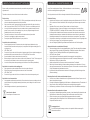
IMPORTANT HAZARD AND SAFETY NOTES (EN) GEFAHREN- & SICHERHEITSHINWEISE (DE)
Please carefully read the below hazard and safety notes before using the height
adjustment unit.
This adds to make the unit work failure-free and avoids accidents.
Electrical safety
• Connect unit to a free accessible 110-230 V / 50 Hz grounded power outlet only. Make sure, the
unit can be immediately separated from the power outlet.
• Only use unit in dry rooms, protect unit from water and other liquids. Only wipe unit with dry
cloth. Do not open lift unit. RISK OF ELECTRIC SHOCK. There are no serviceable parts inside.
• In case of disfunction unplug unit from power outlet and call an authorised technical service
person. Do not overrun line cord or damage in any other way. Replace damaged line cords
immediately with new one from same type.
• The socket connections of the unit and the wall socket must be easily accessible.
• The device is not dripping or splash water protected.
• Do not place objects lled with liquids on or spray the device.
General hints for mechanical safety
• Do not improperly load unit. Do not mount other than original parts (whiteboard, wings,
interactive board, interactive monitor, projector) in conjunction with original mounting parts. Do
not hang on unit.
• VERY HEAVY UNIT.
• Severe risk of injury when unit falls over due to improper usage. Only use original mounting parts
provided with the system. Max load of lift unit is 150 kg/ 330 lbs. Do not exceed.
• Assure installation of unit by authorized service person only.
• Before moving the unit up or down ashure at least a safety distance of 20 cm/ 7.9 from any part of
the unit to any other tment in order to avoid shear traps or squeezing points.
• In case of accident please release operating panel. Movement of unit will stop immediately.
Special hints for moveable und free standing units
• Only operate unit on plane and stable oors. Move unit on plane oors only.
• Risk of tilting when overrunning oorunevennesses, door sills and similar.
• VERY HEAVY UNIT.
• Severe risk of injury when unit falls over. Lock brakes of front wheels when operating unit.
Special hints for wall mounted units
• Use appropriate wall mounting material only. Choose douwels and screws according to the wall
type and material. Using improper mounting material may result in tilting of the unit and severe
risk of injury.
• Wall mounting must be done by experienced personal only.
Instructions for disposal
Do not dispose to consumer waste.
Lesen Sie die nachfolgenden Gefahren- & Sicherheitshinweise vor der Verwendung
der Höhenverstellungseinheit sorgfältig durch.
Dies trägt dazu bei, dass die Einheit störungsfrei arbeitet & Unfälle vermieden werden.
Elektrische Sicherhe
• Anschluss der Einheit nur an eine frei zugängliche schutzgeerdete Steckdose mit 110-230 Volt
/ 50 Hz, damit das Gerät im Notfall direkt, ohne Verzögerung vom Stromnetz getrennt werden
kann.
• Betrieb der Einheit nur in trockenen Räumen erlaubt, vor Wasser & anderen
Flüssigkeiten schützen. System zur Reinigung nur trocken abwischen. Gerät nicht öffnen.
STROMSCHLAGGEFAHR. Es benden sich keine wartbaren Teile im Inneren der Hubsäule.
• Im Störungsfall die Hubeinheit vom Stromnetz trennen und einen authorisierten technischen
Kundendienst benachrichtigen. Netzkabel nicht überfahren oder auf andere Art beschädigen.
Beschädigte Netzkabel nicht mehr verwenden und sofort durch neue gleichen Typs ersetzen.
• Die elektrischen Anschlüsse an der Hubsäule und an der Wand müssen stets frei zugänglich sein.
• Das Gerät ist nicht gegen Tropf- und Spritzwasser geschützt.
• Keine mit Flüssigkeit gefüllten Gegenstände darauf abstellen oder das Gerät besprühen.
Allgemeine Hinweise zur mechanischen Sicherheit
• Höhenverstellungseinheit nicht unsachgemäß belasten. Keine Teile außer den dafür bestimmten
und geeigneten Teilen verwenden (Projektionsäche, Tafelügel, interaktives Board, Monitor,
Projektor). Nicht an Tafelügel, Mitteläche oder Projektorhalterung hängen.
• ACHTUNG: Hohes Gewicht.
• Durch Umfallen der Einheit besteht ernsthafte Verletzungsgefahr. Nur mitgeliefertes
• Original-Befestigungsmaterial und Originalteile verwenden. Die maximale Belastung der
Hubeinheit von 150 kg nicht überschreiten.
• Aufbau und Anschluss des Systems nur durch den authorisierten Fachhandel.
• Beim Hoch- & Herunterfahren der Höhenverstellung mindestens einen Abstand von 20 cm zu
allen am System anmontierten Teilen einhalten um Quetsch- & Scherstellen zu vermeiden. Stellen
Sie die Einsehbarkeit des Arbeitsbereiches sicher.
• Im Gefahrenfall sofort die Bedieneinheit loslassen. Die Bewegung der Hubsäule stoppt sofort
(Totmannschaltung).
Besondere Hinweise für fahrbare und freistehende Systeme
• Die Einheit nur auf ebenen & standsicheren Untergründen betreiben. Fahrbare Systeme nur auf
ebenen Untergründen bewegen.
• Es besteht insbesondere Kippgefahr beim Überfahren von Bodenunebenheiten, Türschwellen o.ä.
• Hohes Gewicht. Durch Umfallen der Einheit besteht ernsthafte Verletzungsgefahr.
• Bei Benutzung von fahrbaren Einheiten vor Benutzung der Einheit Feststellbremsen betätigen.
Besondere Hinweise für wandmontierte Systeme
• Nur geeignetes Wandbefestigungsmaterial verwenden. Je nach bauseitigen Gegebenheiten und
Eigenschaften der Wand müssen geeignete Dübel und Schrauben verwendet werden.
• Bei der Verwendung von ungeeignetem Befestigungsmaterial besteht ernsthafte
Verletzungsgefahr durch Umkippen der Einheit. Wandmontage nur durch ausgebildetes
Fachpersonal ausführen lassen.
Entsorgungshinweis
Gerät nicht im Hausmüll entsorgen, sondern einer speziellen Wiederverwertung für
Elektroschrott zuführen.

23.9
-
 1
1
-
 2
2
-
 3
3
-
 4
4
-
 5
5
-
 6
6
-
 7
7
-
 8
8
-
 9
9


em outras línguas
- español: Neomounts M2250SILVER Manual de usuario
- français: Neomounts M2250SILVER Manuel utilisateur
- English: Neomounts M2250SILVER User manual
- Deutsch: Neomounts M2250SILVER Benutzerhandbuch
- polski: Neomounts M2250SILVER Instrukcja obsługi

