Dolmar MS3524R Manual do proprietário
- Categoria
- Ferramentas de jardim
- Tipo
- Manual do proprietário

Backpack BrushCutter
Débroussailleuse à dos
Rücken tragbare Benzin Motorsense
Decespugliatore a Zaino
Op de rug braagbare Bosmaaier
Desbrozadora de mochila
Cortador de Grama Tipo Mochila
ORIGINAL INSTRUCTION MANUAL
MANUEL D'INSTRUCTIONS ORIGINAL
ORIGINALBEDIENUNGSANLEITUNG
MS-352.4 R
English / French / German
Italian / Dutch / Spanish / Português
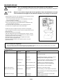
Warning
Read this instruction manual carefully before putting the Brush
Cutter into operation and strictly observe the safety regulations!
Preserve instruction manual carefully!
Avertissement
Lire attentivement ce manuel d’instruction avant d’utiliser la
Débroussailleuse et observer rigoureusement les règles de
sécurité!
Conserver ce manuel dans un endroit sûr!
Waarschuwing
Lesen Sie diese Betriebsanleitung vor der lnbetriebnahme der
Montorsense sufmerksam durch und halten Sie die
Sicherheitsvorschriften genau ein!
Bewahren Sie diese Betriebsanleitung sorgfältig auf!
MS-352.4 R
MANUALE DI ISTRUZIONI ORIGINALE
ORIGINELE GEBRUIKSAANWIJZING
MANUAL DE INSTRUCCIONES ORIGINAL
MANUAL DE INSTRUÇÕES ORIGINAL
Attenzione
Leggete attentamente questo manuale di istruzioni prima di far
funzionare il Decespugliatore, ed osservate rigorosamente le
regole sulla sicurezza!
Conservate con cura questo manuale di instruzioni!
Waarschuwing
Lees deze gebruiksaanwijzing zorgvuldig alvorens de
Bosmaaier in gebruik te nemen en neem de
veiligheidsvoorschriften strict in acht!
Bewaar deze gebruiksaanwijzing zorgvuldig!
Advertencia
Lea atentamente este manual de instrucciones antes de poner
en funcionamiento el Desbrozadora y cumpla estrictamente los
reglamentos de seguridad.
Guarde cuidadosamente este manual de instrucciones.
Advertência
Leia este manual cuidadosamente antes de pôr o Cortador de
grama tipo mochila em funcionamento e observe rigorosamente
as normas de segurança.
Conserve este manual de instruções com cuidado.

2
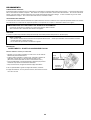
Thank you very much for selecting the DOLMAR Brush Cutter. We
are pleased to be able to you the DOLMAR Brush Cutter which is
the result of a long development programme and many years of
knowledge and experience.
Please read, understand and follow this booklet which refers in
detail to the various points that will demonstrate its outstanding
performance. This will assist you to safely obtain the best
possible result from your DOLMAR Brush Cutter.
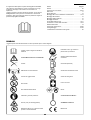
Table of Contents Page
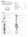
Symbols ......................................................................................... 2
Safety instructions ..................................................................... 3-6
Technical data ............................................................................... 8
Designation of parts ...................................................................... 9
Assembly of engine and drive shaft ...................................... 10-11
Mounting of handle ...................................................................... 12
Mounting of protector .................................................................. 12
Mounting of cutter blade .............................................................. 12
Before start of operation ........................................................ 13-14
Point in operation and how to stop ......................................... 15-16
Resharpening the cutter blade .................................................... 16
Servicing instructions ............................................................. 17-19
Storage ................................................................................... 20-21
Troubleshooting procedures ....................................................... 22
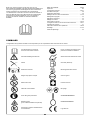
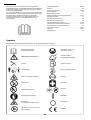
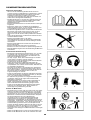
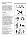
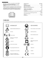
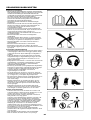
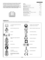
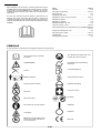
SYMBOLS
It is very important to undestand the following symbols when reading this instructions manual.
WARNING/DANGER/CAUTION
Read instruction Manual
Forbidden
No Smoking
No open flame
Protective gloves must be worn
Keep the area of operation clear of all
persons and pets
Wear protective helmet, eye and ear
protection
Engine-Manual start
Emergency stop
First Aid
ON/START
OFF/STOP
Flying object hazard
Fuel (Gasoline)
Keep distance
Kickback (for Brush Cutter only)
CE mark
Top pemissible tool speed
Recycling
English

3
SAFETY INSTRUCTIONS
General Instructions
– To ensure correct and safe operation, the user must read,
understand and follow this instruction manual to assure
familiarity with the handling of the brush cutter. Users insuffi-
ciently informed will risk danger to themselves as well as others
due to improper handling.
– It is recommended only to loan the brush cutter to people who
have proven to be experienced with brush cutters.
Always hand over the instruction manual.
– Use brush cutters with the utmost care and attention.
– First-time users should ask the dealer for basic instructions to
familiarize oneself with the handling of an engine powered
cutter.
– Children and young persons aged under 18 years must not be
allowed to operate the brush cutter. Persons over the age of
16 years may however use the tool for the purpose of being
trained only while under the direct supervision of a qualified
trainer.
– Use brush cutters with the utmost care and attention.
– Operate the brush cutter only if you are in good physical
condition. Perform all work conscientiously and carefully. The
user has to accept responsibility for others.
– Never use the brush cutter while under the influence of alcohol
or drugs.
– Do not use the unit when you are tired.
– Save these instructions for future referral.
– National regulation can restrict the use of the machine.
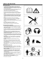
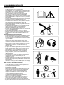
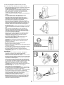
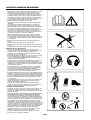
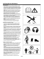
Personal protective equipment
– The clothing worn should be functional and appropriate, i.e. it
should be tight-fitting but not cause hindrance. Do not wear
jewelry, clothing or long hair which could become entangled
with bushes or shrubs.
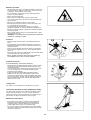
– In order to avoid head-, eye-, hand- or foot injuries as well as to
protect your hearing the following protective equipment and
protective clothing must be used during operation of the brush
cutter.
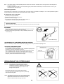
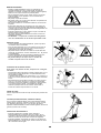
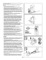
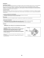
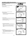
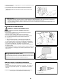
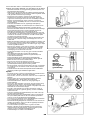
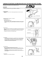
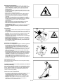
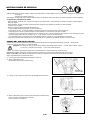
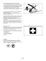
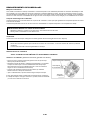
– Always wear a helmet when working in the forest. The
protective helmet (1) is to be checed at regular intervals for
damage and is to be replaced at least every 5 years. Use only
approved protective helmets.
– The visor (2) of the helmet (or approved goggles) protects the
face from flying sticks, stones or other object. During operation
of the brush cutter always wear goggles, or a visor to prevent
eye injuries.
– Wear adequate noise protection equipment to avoid hearing
impairment (ear muffs (3), ear plugs etc.), especially during
extended work periods.
– The work overalls (4) protect against flying stones and
splinters.
We strongly recommend that the user wear work overalls.
– Special gloves (5) made of thick leather are part of the pre-
scribed equipment and must always be worn during operation
of the brush cutter.
– When using the brush cutter, always wear sturdy shoes (6)
with a non-slip sole. This protects against injuries and ensures
good footing.
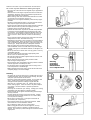
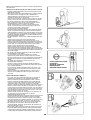
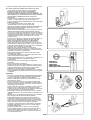
Starting up the brush cutter
– Please make sure that there are no children or other people
within a working range of 50 ft. or 15 meters, also pay attention
to any animals in the working vicinity.
– Before operating, always check that the brush cutter is
safe for operation:
Check the security of the cutter blade. Be sure the blade
mounting nut is firmly secured. The throttle lever should be
checked for smooth and easy action. Check for proper
functioning of the throttle lever lock. The cutter blade must not
rotate during idling.
Consult idle adjustment instructions on page 16. Check for
clean and dry handles and test the function of the STOP switch.
Keep handles free of oil and fuel.
– Before operation, check and follow local; regulations concern-
ing sound level and hours of operations.
– Only start the brush cutter positioned on the ground.
– Do not start it on the back.
1
2
3
4
5
6

4
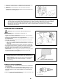
Start the brush cutter only in accordance with the instructions.
Do not use any other methods for starting the engine!
– Use the brush cutter and the tools supplied only for applications
specified.
– Start the brush cutter engine only after the entire tool has been
assembled. Operation of the tool is permitted only after all the
appropriate accessories are attached!
– Before starting, make sure that the cutter blade will not contact
any objects such as branches, stones, etc.
– The engine is to be stopped immediately if there are any engine
problems.
– Should the cutter blade hit stones or any other objects immedi-
ately stop the engine and inspect the cutter blade.
– Inspect the cutter blade at frequent regular intervals for damage
(detect hairline cracks by means of a tapping-noise test).
– A familiar ringing sound should be heard.
– Operate the brush cutter only with the shoulder strap attached.
It should be properly adjusted before putting the brush cutter
into operation. It is essential to adjust the shoulder strap to the
user’s size to prevent fatigue occurring during use or loss of
control of the tool. Never hold the tool with one hand during
use.
– During operation always hold the brush cutter with both hands.
Always ensure a safe, well-balanced footing.
– Operate the brush cutter in such a manner as to avoid inhalation
of the exhaust gases. Never run the engine in enclosed rooms
(risk of suffocation and gas poisoning). Carbon monoxide is an
odorless gas. Always ensure there is adequate ventilation.
– Stop the engine when resting and when leaving the brush
cutter unattended. Place it in a sale location to prevent danger
to others, setting fire to combustible materials, or damage to the
machine.
– Never lay down the hot brush cutter onto dry grass or onto any
combustible materials.
– The cutter blade must be used with its appropriate guard.
Never run the tool without this guard!
– All protective parts and guards supplied with the machine must
be used during operation.
– Never operate the engine with a faulty exhaust muffler.
– Stop the engine during transport.
– During transport over long distances the tool protection included
with the equipment must always be used.
– Put the brush cutter in upright position and fix it during care or
truck transportation to avoid damage.
– When transporting the brush cutter, ensure that the fuel tank is
completely empty, to avoid fuel leakage.
Refuelling
– To reduce the risk of fire and bum injury, handle fuel with care it
is highly flammable, Stop the engine during refuelling, keep well
away from open flame and do not smoke.
– Avoid skin contact with petroleum products. Do not inhale fuel
vapor. Always wear protective gloves during refuelling.
Change and clean protective clothing at regular intervals.
– Take care not to spill either fuel or oil. Always wipe unit dry
before starting engine. Allow wet cloths to dry before dispos-
ing in proper, covered container to prevent spontaneous
combustion.
– Avoid any fuel contact with your clothing. Change your clothing
immediately if fuel has spilled on it (danger hazard).
– Inspect the fuel cap at regular intervals making sure that stays
securely fastened.
– Carefully tighten the locking screw of the fuel tank. Change
locations to start the engine (at least 10ft. or 3 meters away
from the place of refueling).
– Never refuel in closed rooms. Fuel vapors accumulate at
ground level (risk of explosions).
– Only transport and store fuel in approved containers. Make
sure stored fuel is not accessible to children.
– Do not attempt to refuel a hot or a running engine.
– When mixing gasoline with two-stroke engine oil, use only
gasoline which contains no ethanol or methanol (types of
alcohol). This will help to prevent damage to fuel lines and other
engine parts.
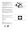
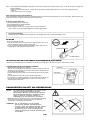
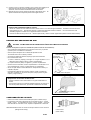
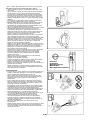
• Resting
• Transport
• Refuelling
• Maintenance
• Tool Repiacement
3m (10FT)

5
Method of operation
– Use the brush cutter only in good light and visibility. During cold
seasons beware of slippery or wet areas, ice and snow (risk
of slipping). Always ensure a safe footing.
– Do not overreach. Keep proper footing, balance and hand
control of the unit at all times.
– Never cut above waist level.
– Never stand on a ladder while running the brush cutter.
– never climb up into trees to perform any cutting operation with
the brush cutter.
– Never work on unstable surfaces or steep terrain.
– Remove all objects such as stones, nails, broken glass, wire,
etc. found within the working ares.
Foreign articles may damage the cutting tool, can cause
dangerous kickbacks, or could be thrown about dangerously.
– Before commencing cutting the cutting tool must have reached
full working speed.
– Never operate this tool while it is turned upside-down or when
it is at an extreme angle.
– !WARNING! — The cutter area is still dangerous while the
machine is coasting to a stop.
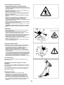
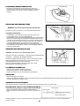
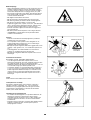
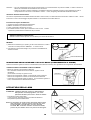
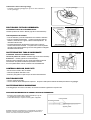
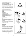
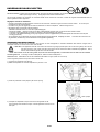
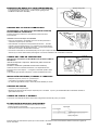
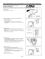
Kickback
– When operating the brush cutter, uncontrolled kickback can
occur.
– This particularly is the case when attempting to cut within a
blade segment between 12 and 2 o’clock as viewed from the
operator’s position.
– Never touch this segment of the brush cutter to solid objects,
such as bushes, stumps, trees, etc., with a diameter greater
than 3 cm.
– The brush cutter will then be deflected at great force and speed
with the potential risk of serious injuries.
– Never operate the brush cutter using the blade seg-
ment between the 12 and 2 o’clock position.
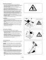
Kickback prevention
To avoid kickbacks, observe the following:
– Operation within the blade segment between 12 and 2 o’clock
can cause serious potential hazards, especially when using
metal cutting blades.
Use of this brush cutter utilizing blade segment positions from
11 to 12 o’clock and 2 to 5 o’clock can still cause a likely
potential for some kickback.
– Cutting operations attempted within the blade segments
between 11 and 12 o’clock, and between 2 and 5 o’clock,
should only be performed by trained and experienced opera-
tors, and only at their own risk. Smooth and easy cutting with
almost no kickback is possible using the blade segment be-
tween 8 and 11 o’clock.
Cutting Tools
Use only the correct cutting tool for the specific job in hand.
Cutter blade (Star Blade (4 teeth), Eddy Blade (8 teeth)):
For cutting thick materials, such as weeds, high grass, bushes,
shrubs, underwood, thicket, etc. (max. 2 cm dia. thickness).
Perform this cutting work by swinging the brush cutter evenly in
half-circles from right to left (similar to using a scythe).
Maintenance instructions
– The condition of the cutter, in particular of the cutter blade,
guard and of the shoulder strap must be checked before
commencing work. Particular attention is to be paid to the
cutting blades which must be correctly sharpened.
– Turn off the engine and remove spark plug connectors when
replacing or sharpening cutting blade, and also when cleaning
the cutter or cutting tool.
Caution: Kickback
Diagrammatic figure
Diagrammatic figure
12
2

6
Never straighten or weld damaged cutting blades.
– Be kind to the environment. Operate the brush cutter with as
little noise and pollution as possible. In particular check the
correct adjustment of the carburetor.
– Clean the brush cutter at regular intervals and check that all
screws and nuts are securely tightened.
– Never service or store the brush cutter in the vicinity of open
flames, sparks, etc.
– Always store the brush cutter in a well-ventilated locked room
and with an emptied fuel tank.
Observe and follow all relevant accident prevention instructions
issued by the trade associations and by insurance companies.
Do not perform any modifications to the brush cutter as this will
risk your safety.
The performance of maintenance or repair work by the user is
limited to those activities s described in this instruction manual. All
other work is to be done by Authorized Service Agents.
Use only genuine spare parts and accessories supplied by
DOLMAR.
Use of non-approved accessories and tools means increased risk
of accidents and injuries. DOLMAR will not accept any liability for
accidents or damage caused by the use of any non-approved
cutting tools attachments or accessories.
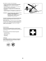
First Aid
In case of accident make sure that a well-stocked first-aid kit is
available in the vicinity of the cutting operations. Immediately
replace any item taken from the first aid box.
When asking for help, please give the following informa-
tion:
– Place of accident
– What happened
– Number of injured persons
– Extent of injuries
– You r n am e
Packaging
The DOLMAR brush cutter is delivered in two protective
cardboard boxes to prevent shipping damage.
Cardboard is a basic raw material and is therefore consequently
reusable or suitable for recycling (waste paper recycling).

7
EC-DECLARATION OF CONFORMITY
Backpack BrushCutter: model MS-352.4 R (See TECHNICAL DATA for the specifications)
We declare under our sole responsibility that this product is in compliance with the following Directives, 2000/14/EC, 2006/42/EC.
The most important standards applied to properly meet the requirements of the adove Directives were: EN11806.
Measured Sound Power: 108.4 dB
Guarantee Sound Power: 113.3 dB
These sound power levels were measured in accordance with Council Directive, 2000/14/EC.
Conformity assessment procedure: Annex V.
3rd. NOV. 2009
Tamiro Kishima Rainer Bergfeld
Managing Director Managing Director
Responsible Manufacturer:
Makita Corporation.
3-11-8,Sumiyoshi-cho, Anjo, Aichi, JAPAN
Authorized Representative in Europe:
DOLMAR Gmbh
Jenfelder Str. 38, 22045 Hamburg, Germany

8
Model
MS-352.4 R
Loop handle
Cutter blade Nylon cutting head
Dimensions : length x width x height (without pipe case length) mm
430 x 280 x 430
Mass (without guard and cutting blade) kg
10.2
Volume (fuel tank) L
0.65
Cutting attachments (cutter blade dia.) mm
255
Engine displacement cm
3
33.5
Maximum engine performance kw
1.07 at 7000 min
-1
Engine speed at recommended max. spindle speed min
-1
10000
Maximum spindle speed (corresponding) min
-1
7500
Fuel consumption kg/h
0.458
Specific fuel consumption g/kwh
426
Idling speed min
-1
3000
Clutch engagement speed min
-1
4100
Carburetor (Diaphragm - carburetor) type
WALBRO WYL
Ignition system type
Solid state ignition
Spark plug type
NGK CMR6A
Electrode gap mm
0.7 – 0.8
a
hv eq
m/s
2
2.1 2.2
Right handle
(Rear grip)
Uncertainty K m/s
2
0.3 1.6
a
hv eq
m/s
2
3.6 3.0
Vibration per
ISO 22867
Left handle
(Front grip)
Uncertainty K m/s
2
0.8 1.9
L
PA eq
dBA
87.3 93.2
Sound pressure level average to
ISO 22868
Uncertainty K dBA
2.2 2.3
L
WA eq
dBA
100.5 105.2
Sound power level average to
ISO 22868
Uncertainty K dBA
2.8 2.6
Fuel
Automobile gasoline
Engine oil
SAE 10W-30 oil API Classification,
Class SF or higher (4-stroke engine for automobile).
Gear ratio
15/20
TECHNICAL DATA

9
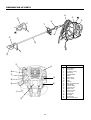
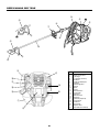
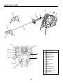
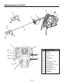
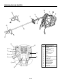
DESIGNATION OF PARTS
Ԣ
ԥ
ԛ
ԣ
Ԟ
Ԥ
Ԡ
Ԝ
ԡ
ԟ
Ԩ
ԩ
ԝ
Ԙ
Ԧ
ԙ
Ԛ
ԧ
Ԫ
ԫ
GB DESIGNATION OF PARTS
1 Fuel Tank
2 Rewind Starter
3 Air Cleaner
4 I-O Switch (on/off)
5 S
p
ark Plu
g
6 Exhaust Muffler
7 Handle
8 Control Lever
9 Control Cable
10 Shaft
11 Protector
12 Gear Case/Head Case
13 Cutter Blade
14 Shoulder Strap
15 Fuel Filler Cap
16 Starter Knob
17 Primmer Pump
18 Choke Lever
19 Exhaust Pi
p
e
20 Oil Gau
g
e
21 Flexible Pipe
22 Nylon Cutting Head
Ԣ
ԣ

10
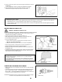
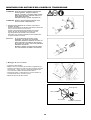
CAUTION : Before performing any work on the brush
cutter, always switch off the motor and pull the
spark plug connectors off the spark plug.
Beware of hot engine pars and sharp blade
edges.
Always wear protective gloves!
CAUTION : Start the brush cutter only after having as-
sembled it completely.
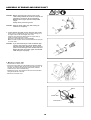
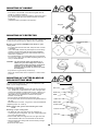
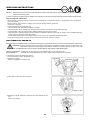
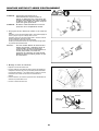
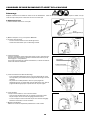
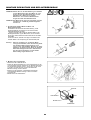
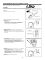
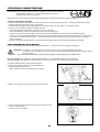
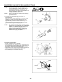
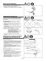
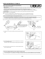
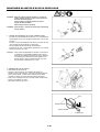
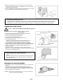
1. Joining flexible pipe with engine and pipe case holder
Insert on end of a flexible pipe (1) into a clutch housing (2) on
an engine until it locks with a slight “click” noise.
Insert the other end of the flexible pipe into a pipe case (3)
holder of a brush cutter until it locks.
Each end of the flexible pipe is interchangeable.
Make sure that a squsre end of a flexible shaft fits into the joint
of a drive shaft.
CAUTION : If you have difficulty to insert the flexible pipe
properly, the square end of the flexible shaft
may not fit the drive shaft joint. Do not force to
push to avoid damage on the flexible shaft end.
Repeat the same procedure again until flexible
shaft and pipe fit properly.
2. Mounting of control cable
– Remove the air cleaner cover.
– Place the control cable (4) in the adjusting bolt (5), and shift the
swivel (6) so that the cable will be put in the swivel groove. At
this time, the round-hole side of the swivel will be oriented
toward the inner wire end-metal fitting.
– Release the swivel, and confirm that the inner wire-end metal
fitting will be placed in the hole.
– Mount the air cleaner cover.
ASSEMBLY OF ENGINE AND DRIVE SHAFT
Round-hole
End fitting
Control cable
Swivel
Insert

11
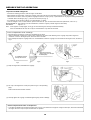
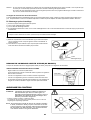
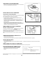
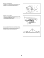
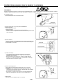
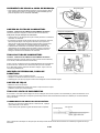
CONNECTION OF SWITCH CORD
– Connect the switch cords to the two cords from the engine by
inserting one into the other.
– Fix the cord connector by clamp (7).
ADJUSTMENT OF CONTROL CABLE
– Adjust the control cable by adjusting bolt so that it will have 1 to
2 mm play when the throttle lever is set to the low-speed
position by carburetor adjusting bolt. (Be careful that the cutter
blade will not turn in idling.)
Make the throttle wire and I-O switch cords go along the flexible
pipe and fix three point them on clip wire (8) tightly. If you do not
fix the throttle wire and I-O switch cords surely, there is fear that
they catch on the branch and so on it is dangerous.

12
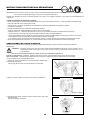
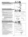
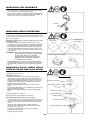
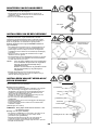
MOUNTING OF HANDLE
– Fix a barrier to the left side of the machine together with the
handle for operator’s protection.
– Do not adjust position of the loop handle too close to the control
grip. Keep not less than 25cm distance between the handle
and the grip.
(a distance collar is provided for this purpose.)
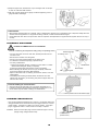
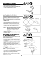
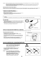
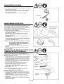
MOUNTING OF PROTECTOR
To meet the applicable safety provisions, only the tool/protector
combinations as indicated in the table must be used. Failure to do
so may result in serious injury or death to user or bystanders.
Be sure to use genuine DOLMAR cutter blade or nylon
cutting head.
– The cutter blade must be well clean, sharp and free of cracks
or breakage.
If the cutter blade contacts any hard objects or stones during
operation, stop the engine and check the blade immediately.
– Clean and sharpen or replace the cutter blade at least every
three hours of operation.
– The outside diameter of the cutter blade must not exceed 255
mm (10-1/32”). Never use any blades surpassing 255 mm (10-
1/32”) in outside diameter.
CAUTION : The appropriate guard must always be in-
stalled, for your own safety and in order to
comply with accident-prevention regulations.
Operation of the equipment without the
protector being properly in place must never
be attempted.
– Fix protector to a gear case by 4 bolts firmly
Never use a blush cutter without a protector or with a broken
protector.
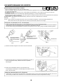
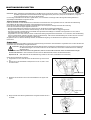
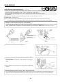
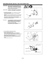
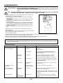
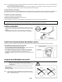
MOUNTING OF CUTTER BLADE OR
NYLON CUTTING HEAD
Turn the machine upside down, and you can replace the cutter
blade or nylon cutting head easily.
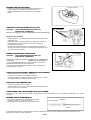
Mounting of cutter blade
– Fit a cutting blade and other parts in the order as in the illustra-
tion. Thrust a bar or allen wrench into a hole of the gear case
until the cutting blade is locked and will not turn. Tighten a nut
by turning to counter-clockwise with a combination wrench.
(Note that the nut is tightened or loosened in the opposit
direction of a usual nut.)
– The nut must be re-tightened every time before use.
– For this brush cutter, we recommend the cutting attachments on
the right.
– Never attempt to cut a tree, a log, wood or other hard materials.
[Tightening torque: 28 – 48 N
m]
NOTE : Always wear gloves when handling the cutter
blade.
Mounting of nylon cutting head
– The blade cap, bolt cover and nut are not necessary for
mounting the nylon cutting head. The nylon cutting head should
go on top of the grass cover.
– Insert the allen wrench through the hole in the gear case and
rotate the blade holder until it is locked with the alln wrench.
– Then screw the nylon cutting head onto the shaft by turning it
counter-clockwise.
– Remove the allen wrench.
Star Blade
Protector for metal
blades
Eddy Blade
Nut
Bolt cover
Blade cap
Blade
Grass cover
Blade holder
Protector plate
Protector
Gear case
Nylon cutting head
to engine

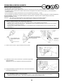
13
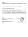
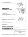
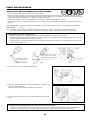
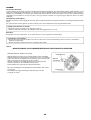
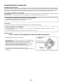
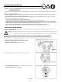
Inspection and Refill of Engine Oil
– Perform the following procedure, with the engine cooled down.
– While keeping the engine level, remove the oil gauge, and confirm that the oil is filled within the upper and lower limit marks.
When the oil is in short in such a way that the oil gauge touches the oil only by its tip, in particular with the oil gauge remaining inserted in the
crankcase without screwing-in (Fig. 1), refill new oil near the port (Fig. 2).
– For reference, the oil refill time is about 15 h (refill frequency: 15 times).
– If the oil changes in color or mixes with dirt, replace it with new one. (For the interval and method of replacement, refer to P. 1 7 )
Recommended oil: SAE 10W-30 oil of API Classification, Class SF or higher (4-stroke engine for automobile)
Oil volume: Approx. 0.1 L
Note: If the engine is not kept upright, oil may go into around the engine, and may be refilled excessively.
If the oil is filled above the limit, the oil may be contaminated or may catch fire with white.
Point 1 in Replacement of Oil "Oil Gauge"
– Remove dust or dirt near the oil refill port, and detach the oil gauge.
– Keep the detached oil gauge free of sand or dust. Otherwise, any sand or dust adhering to the oil gauge may cause irregular oil
circulation or wear on the engine parts, which will result in troubles.
– As an example to keep the oil gauge clean, it is recommended to insert the oil gauge on its knob side into the engine cover, as shown in
Fig.3.
(1) Keep the engine level, and detach the oil gauge.
(2) Fill oil up to the edge of the oil refill port. (Refer to Fig.2 of the preceding
page).
Feed oil with the lubricant refill container.
(3) Securely tighten the oil gauge. Insufficient tightening may cause oil leakage.
Point 2 in Replacement of Oil: “If oil spills out”
– If oil spills out between the fuel tank and engine main unit, the oil is sucked into through the cooling air intake port, which will contaminate
the engine. Be sure to wipe out spilt oil before start of operation.
BEFORE START OF OPERATION
Fig.2
Upper limit of oil level
(Lower part of oil refill port
threaded part)
If oil adheres around
this tip refill new oil.
Fig.1
Oil gauge
Fig.3

14
Handling of Fuel
It is necessary to handle fuel with utmost care. Fuel may contain substances similar to solvents. Refueling must be performed in a sufficiently
ventilated room or in the open air. Never inhale fuel vapor, and keep fuel away from you. If you touch fuel repeatedly or for a long time, the skin
becomes dry, which may cause skin disease or allergy. If fuel enters into the eye, clean the eye with fresh water. If your eye remains still irritated,
consult your doctor.
Storage Period of Fuel
Fuel should be used up within a period of 4 weeks, even if it is kept in a special container in a well-ventilated shade.
If a special container is not used or if the container is not covered, fuel may deteriorate in one day.
STORAGE OF MACHINE AND REFILL TANK
– Keep the machine and tank at a cool place free from direct sunshine.
– Never keep the fuel in the cabin or trunk.
Fuel
The engine is a four-stroke engine. Be sure to use an automobile gasoline (regular gasoline or premium gasoline).
Points for Fuel
– Never use a gasoline mixture which contains engine oil. Otherwise, it will cause excessive carbon accumulation or mechanical troubles.
– Use of deteriorated oil will cause irregular startup.
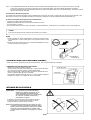
Refueling
WARNING: INFLAMMABLES STRICTLY PROHIBITED
Gasoline Usedl: Automobile gasoline (unleaded gasoline)
– Loosen the tank cap a little so that there will be no difference in atmospheric
pressure.
– Detach the tank cap, and refuel, discharging air by tilting the fuel tank so that
the refuel port will be oriented upward. (Never refill fuel full to the oil refill
port.)
– Wipe well the periphery of the tank cap to prevent foreign matter from
entering into the fuel tank.
– After refueling, securely tighten the tank cap.
• If there is any flaw or damage on the tank cap, replace it.
• The tank cap is consumable, and therefore should be renewed every two to
three years.
REFUELING
Fuel tank cap
Fuel upper limit
Fuel tank

15
POINTS IN OPERATION AND HOW TO STOP
Observe all applicable accident prevention regulations!
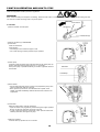
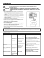
STARTING
Move at least 3m away from the place of refuelling. Place the brush cutter on a clean piece of ground taking care that the cutting tool does
not come into contact with the ground or any other objects.
A:Cold start
1) Set this machine on a flat space.
2) Set the I-O switch (1) to OPERATION.
3) Choke lever
Close the choke lever.
Choke opening:
– Full closing in cold or when the engine is cold.
– Full or half opening in restart just after stop of operation.
4) Primer pump
Continue to push the primer pump until fuel enters into the primer pump. (In
general, fuel enters into the primer pump by 7 to 10 pushes.)
If the primer pump is pushed excessively, an excess of gasoline returns to
the fuel tank.
5) Recoil starter
– Pull the start knob gently until it is hard to pull (compression point). Then,
return the start knob, and pull it strongly.
– Never pull the rope to the full. Once the start knob is pulled, never
release your hand immediately. Hold the start knob until it returns to its
original point.
6) Choke lever
When the engine starts, open the choke lever.
– Open the choke lever progressively while checking the engine operation.
Be sure to open the choke lever to the full in the end.
– In cold or when the engine is cooled down, never open the choke lever
suddenly. Otherwise, the engine may stop.
7) Warm-up operation
Continue warm-up operation for 2 to 3 minutes.
I-O switch (1)
Lock-off lever
Throttle lever(6)
OPERATION
Caburettor
Primer Pump

16
Note: – If the starter handle is pulled repeatedly when the choke lever remains at "CLOSE" position, the engine will not start easily due to
excessive fuel intake.
– In case of excessive fuel intake, remove the spark plug and pull the starter handle slowly to remove excess fuel. Also, dry the
electrode section of the spark plug.
Caution during operation:
If the throttle lever is opened fully in a no-load operation, the engine rotation is increased to 10,000rpm or more. Never operate the engine at
a higher speed than required and at an approximate speed of 6,000 - 8,500rpm.
B: Startup after warm-up operation
1) Push the primer pump repeatedly.
2) Keep the throttle lever at the idling position.
3) Pull the recoil starter strongly.
4) If it is difficult to start the engine, open the throttle by about 1/3.
Pay attention to the cutter blade which may rotate.
Attention in Operation
When the engine is operated upside down, white smoke may come out from the muffler.
STOPPING
1) Release the throttle lever (6) fully, and when the engine rpm has lowered,
set the I-O switch to STOP the engine will now stop.
2) Be aware that the cutting head may not stop immediately and allow it to
slow down fully.
I-O switch (1)
STOP
Throttle lever (6)
When it is necessary to adjust the low-speed rotation (idling), perform it by the carburetor adjusting screw.
ADJUSTMENT OF LOW-SPEED ROTATION (IDLING)
CHECKUP OF LOW-SPEED ROTATION
– Set the low-speed rotation to 3000min
-1
.
If it is necessary to change the rotation speed, regulate the adjusting screw
(illustrated on the left), with Phillips screwdriver.
– Turn the adjusting screw to the right, and the engine rotation will increase.
Turn the adjusting screw to the left, and the engine rotation will drop.
– The carburetor is generally adjusted before shipment. If it is necessary to
readjust it, please contact Authorized Service Agent.
RESHARPNING THE CUTTER BLADE
CAUTION : The cutter blade mentioned below must only be
resharpened by an authorized facility. Manual
resharpening will result in imbalances of the cutting
tool causing potentially dangerous vibrations and
damage to the equipment.
– Cutter blade (Star blade (4 teeth), Eddy blade (8 teeth))
An expert resharpening and balancing service is provided by
Authorized Service Agents.
NOTE : To increase the service life of the cutter blade (star blade,
eddy blade) it may be turned over once, until both cutting
edges have become dull. Never continue to use a dull
blade or kickback and serious injury may result.
Adjusting screw
Carburetor

17
SERVICING INSTRUCTIONS
CAUTION : Before doing any work on the brush cutter, always stop the engine and pull the plug cap off the spark plug (see "checking the spark plug").
Always wear protective gloves!
To ensure a long service life and to avoid any damage to the equipment, the following servicing operations should be performed at regular intervals.
Daily checkup and maintenance
– Before operation, check the machine for loose screws or missing parts. Pay particular attention to the tightness of the cutter blade or
nylon cutting head.
– Before operation, always check for clogging of the cooling air passage and the cylinder fins.
Clean them if necessary.
– Perform the following work daily after use:
• Clean the brush cutter externally and inspect for damage.
• Clean the air filter. When working under extremely dusty conditions, clean the filter the severall times a day.
• Check the blade or the nylon cutting head for damage and make sure it is firmly mounted.
• Check that there is sufficient difference between idling and engagement speed to ensure that the cutting tool is at a standstill while the
engine is idling (if necessary reduce idling speed).
If under idling conditions the tool should still continue to run, consult your nearest Authorized Service Agent.
– Check the functioning of the I-O switch, the lock-off lever, the control lever, and the look button.
REPLACEMENT OF ENGINE OIL
Deteriorated engine oil will shorten the life of the sliding and rotating parts to a great extent. Be sure to check the period and quantity of replacement.
ATTENTION: In general, the engine main unit and engine oil still remain hot just after the engine is stopped. In replacement of oil,
confirm that the engine main unit and engine oil are sufficiently cooled down. Otherwise, there may remain a risk of scald.
Note: If the oil filled above the limit, it may be contaminated or may catch fire with white smoke.
Interval of replacement: Initially, every 20 operating hours, and subsequently every 50 operating hours
Recommended oil: SAE10W-30 oil of API Classification SF Class or higher (4-stroke engine oil for automobile)
In replacement, perform the following procedure.
1) Confirm that the tank cap is tightened securely.
2) Detach the oil gauge.
Keep the oil gauge free from dust or dirt.
3) Place waste or paper near the oil refill port.
4) Detach the oil gauge, and drain oil, tilting the main unit toward the oil refill
port
Drain oil in a container.
Waste or paper
Fuel tank cap
Oil gauge

18
5) Keep the engine level, and feed new oil up to the edge of the oil refill port.
In refill, use a lubricant refill container.
6) After refill, securely tighten the oil gauge. Insufficient tightening of the oil
gauge will lead to oil leakage.
POINTS ON OIL
– Never discard replaced engine oil in garbage, earth or sewage ditch. Disposal of oil is regulated by law. In disposal, always follow the
relevant laws and regulations. For any points remaining unknown, contact Authorized Service Agent.
– Oil will deteriorate even when it is kept unused. Perform inspection and replacement at regular intervals (replace with new oil every 6
months).
CLEANING OF AIR CLEANER
DANGER: INFLAMMABLES STRICTLY PROHIBITED
Interval of Cleaning and Inspection: Daily (every 10 operating hours)
– Turn the choke lever to the full close side, and keep the carburetor off
from dust or dirt.
– Remove the air cleaner cover-fixing bolts.
– Pull the cover lower side and detach the air cleaner cover.
– If oil adheres to the element (sponge), squeeze it firmly.
– For heavy contamination:
1) Remove the element (sponge), immerse it in warm water or in water-
diluted neutral detergent, and dry it completely.
2) Clean the element (felt) with gasoline, and dry it completely.
– Before attaching the element, be sure to dry it completely. Insufficient
drying of the element may lead to difficult startup.
– Wipe out with waste cloth, oil adhering around the air cleaner cover and
plate breather.
– Immediately after cleaning is finished, attach the cleaner cover and
tighten it with fixing bolts. (In remounting, first place the upper claw, and
then the lower claw.)
Points in Handling Air Cleaner Element
– Clean the element several times a day, if excessive dust adheres to it.
– If operation continues with the element remaining not cleared of oil, oil in
the air cleaner may fall outside, resulting in oil contamination.
CHECKING THE SPARK PLUG
– Only use the supplied universal wrench to remove or to install the spark plug.
– The gap between the two electrodes of the spark plug should be 0.7-0.8mm
(0.028"-0.032"). If the gap is too wide or too narrow, adjust it. If the spark
plug is clogged with carton or fouled, clean it thoroubhly or replace it.
CAUTION : Never touch the spark plug connector while the engine is running
(danger of high voltage electric shock).
Plate
Fixing bolt
Air cleaner cover
Element (sponge)
Breather Part
Element (felt)
Pick this part and remove the element (felt).
0.7 mm - 0.8 mm
(0.028”-0.032”)

19
SUPPLY OF GREASE TO GEAR CASE
– Supply grease (Shell Alvania 2 or equivalent) to the gear case through the
grease hole every 30 hours. (Genuine DOLMAR grease may be purchased
from your DOLMAR dealer.)
CLEANING OF FUEL FILTER
WARNING: INFLAMMABLES STRICTLY PROHIBITED
Interval of Cleaning and Inspection: Monthly (every 50 operating hours)
Suction head in the fuel tank
– The fuel filler (1) of the suction head is used to filler the fuel required by the
carburetor.
– A periodical visual inspection of the fuel filter is to be conducted. For that
purpose open the tank cap, use a wire hook and pull out the suction head
through the tank opening. Filters found to have hardened, been polluted or
clogged up are to be replaced.
– Insufficient fuel supply can result in the admissible maximum speed being
exceeded. It is therefore important to replace the fuel filter at least quarterly to
ensure satisfactory fuel supply to the carburetor.
REPLACEMENT OF FUEL PIPE
CAUTION: INFLAMMABLES STRICTLY PROHIBITED
Interval of Cleaning and Inspection: Daily (every 10 operating hours)
Replacement: Annually (every 200 operating hours)
Replace the fuel pipe every year, regardless of operating frequency. Fuel leakage
may lead to fire.
If any leakage is detected during inspection, replace the oil pipe immediately.
INSPECTION OF BOLTS, NUTS AND SCREWS
– Retighten loose bolts, nuts, etc.
– Check for fuel and oil leakage.
– Replace damaged parts with new ones for safety operation.
CLEANING OF PARTS
– Keep the engine always clean.
– Keep the cylinder fins free of dust or dirt. Dust or dirt adhering to the fins will cause seizure.
REPLACEMENT OF GASKETS AND PACKINGS
In reassembling after the engine is dismounted, be sure to replace the gaskets and packings with new ones.
SUPPLY OF GREASE TO THE FLEXIBLE SHAFT
- Pull out the flexible shaft from the flexible lining for every 20 hours,
and apply grease on the flexible shaft.
- The flxible shaft may be broken if no grease is applied.
Grease hole
Fuel filter (1)
Hose clamp
Fuel pipe
Fuel pipe
Any maintenance of adjustment work that is not been included and described in this manual is only to be performed by Authorized Service
Agents.
Flexible shaft
Flexible liner
Apply grease

20
STORAGE
WARNING: When draining the fuel, be sure to stop the engine and confirm that the engine cools
down.
Just after stopping the engine, it may still hot with possibility of burns, inflammability and fire.
ATTENTION: When the machine is kept out of operation for a long time, drain up all fuel from the
fuel tank and carburetor, and keep it at a dry and clean place.
Fault location
– Drain up fuel from the fuel tank and carburetor according to the following
procedure:
1) Remove the fuel tank cap, and drain fuel completely.
If there is any foreign matter remaining in the fuel tank, remove it
completely.
2) Pull out the fuel filter from the refill port using a wire.
3) Push the primer pump until fuel is drained from there, and drain fuel
coming into the fuel tank.
4) Reset the filter to the fuel tank, and securely tighten the fuel tank cap.
5) Then, continue to operate the engine until it stops.
– Remove the spark plug, and drip several drops of engine oil through the
spark plug hole.
– Gently pull the starter handle so that engine oil will spread over the engine,
and attach the spark plug.
– Attach the cover to the cutter blade.
– During storage, keep the rod horizontal or keep the machine upright with the
blade edge oriented upward. (In this case, pay full attention to prevent the
machine from falling.)
Never store the machine with the cutter blade edge oriented downward.
Lubricating oil may spill out.
– Keep the drained fuel in a special container in a well-ventilated shade.
Attention after long-time storage
– Before startup after long-time shutdown, be sure to replace oil (refer to P 17). Oil will deteriorate while the machine is kept out of
operation.
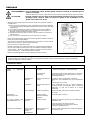
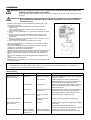
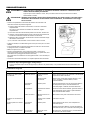
Fault System Observation Cause
Engine not starting or with
difficulty
Ignition system Ignition spark O.K.
Fault in fuel supply or compression system, mechanical
defect
No ignition spark
STOP-switch operated, wiring fault or short circuit, spark
plug or connector defective, ignition module faulty
Fuel supply Fuel tank filled
Incorrect choke position, carburetor defective, fuel supply
line bent or blocked, fuel dirty.
Compression
No compression when
pulled over
Cylinder bottom gasket defective, crankshaft seals
damaged, cylinder or piston rings defective or improper
sealing of spark plug
Mechanical fault Starter not engaging Broken starter spring, broken parts inside of the engine
Warm start problems
Tank filled ignition spark
existing
Carburetor contaminated, have it cleaned
Engine starts but dies Fuel supply Tank filled Incorrect idling adjustment, carburetor contaminated
Fuel tank vent defective, fuel supply line interrupted,
cable or STOP-switch faulty
Insufficient performance
Several systems
may simultaneously
be affected
Engine idling poor
Air filter contaminated, carburetor contaminated, muffler
clogged, exhaust duct in the cylinder clogged
A página está carregando...
A página está carregando...
A página está carregando...
A página está carregando...
A página está carregando...
A página está carregando...
A página está carregando...
A página está carregando...
A página está carregando...
A página está carregando...
A página está carregando...
A página está carregando...
A página está carregando...
A página está carregando...
A página está carregando...
A página está carregando...
A página está carregando...
A página está carregando...
A página está carregando...
A página está carregando...
A página está carregando...
A página está carregando...
A página está carregando...
A página está carregando...
A página está carregando...
A página está carregando...
A página está carregando...
A página está carregando...
A página está carregando...
A página está carregando...
A página está carregando...
A página está carregando...
A página está carregando...
A página está carregando...
A página está carregando...
A página está carregando...
A página está carregando...
A página está carregando...
A página está carregando...
A página está carregando...
A página está carregando...
A página está carregando...
A página está carregando...
A página está carregando...
A página está carregando...
A página está carregando...
A página está carregando...
A página está carregando...
A página está carregando...
A página está carregando...
A página está carregando...
A página está carregando...
A página está carregando...
A página está carregando...
A página está carregando...
A página está carregando...
A página está carregando...
A página está carregando...
A página está carregando...
A página está carregando...
A página está carregando...
A página está carregando...
A página está carregando...
A página está carregando...
A página está carregando...
A página está carregando...
A página está carregando...
A página está carregando...
A página está carregando...
A página está carregando...
A página está carregando...
A página está carregando...
A página está carregando...
A página está carregando...
A página está carregando...
A página está carregando...
A página está carregando...
A página está carregando...
A página está carregando...
A página está carregando...
A página está carregando...
A página está carregando...
A página está carregando...
A página está carregando...
A página está carregando...
A página está carregando...
A página está carregando...
A página está carregando...
A página está carregando...
A página está carregando...
A página está carregando...
A página está carregando...
A página está carregando...
A página está carregando...
A página está carregando...
A página está carregando...
A página está carregando...
A página está carregando...
A página está carregando...
A página está carregando...
A página está carregando...
A página está carregando...
A página está carregando...
A página está carregando...
A página está carregando...
A página está carregando...
A página está carregando...
A página está carregando...
A página está carregando...
A página está carregando...
A página está carregando...
A página está carregando...
A página está carregando...
A página está carregando...
A página está carregando...
A página está carregando...
A página está carregando...
A página está carregando...
A página está carregando...
A página está carregando...
A página está carregando...
A página está carregando...
A página está carregando...
A página está carregando...
A página está carregando...
A página está carregando...
A página está carregando...
A página está carregando...
A página está carregando...
A página está carregando...
-
 1
1
-
 2
2
-
 3
3
-
 4
4
-
 5
5
-
 6
6
-
 7
7
-
 8
8
-
 9
9
-
 10
10
-
 11
11
-
 12
12
-
 13
13
-
 14
14
-
 15
15
-
 16
16
-
 17
17
-
 18
18
-
 19
19
-
 20
20
-
 21
21
-
 22
22
-
 23
23
-
 24
24
-
 25
25
-
 26
26
-
 27
27
-
 28
28
-
 29
29
-
 30
30
-
 31
31
-
 32
32
-
 33
33
-
 34
34
-
 35
35
-
 36
36
-
 37
37
-
 38
38
-
 39
39
-
 40
40
-
 41
41
-
 42
42
-
 43
43
-
 44
44
-
 45
45
-
 46
46
-
 47
47
-
 48
48
-
 49
49
-
 50
50
-
 51
51
-
 52
52
-
 53
53
-
 54
54
-
 55
55
-
 56
56
-
 57
57
-
 58
58
-
 59
59
-
 60
60
-
 61
61
-
 62
62
-
 63
63
-
 64
64
-
 65
65
-
 66
66
-
 67
67
-
 68
68
-
 69
69
-
 70
70
-
 71
71
-
 72
72
-
 73
73
-
 74
74
-
 75
75
-
 76
76
-
 77
77
-
 78
78
-
 79
79
-
 80
80
-
 81
81
-
 82
82
-
 83
83
-
 84
84
-
 85
85
-
 86
86
-
 87
87
-
 88
88
-
 89
89
-
 90
90
-
 91
91
-
 92
92
-
 93
93
-
 94
94
-
 95
95
-
 96
96
-
 97
97
-
 98
98
-
 99
99
-
 100
100
-
 101
101
-
 102
102
-
 103
103
-
 104
104
-
 105
105
-
 106
106
-
 107
107
-
 108
108
-
 109
109
-
 110
110
-
 111
111
-
 112
112
-
 113
113
-
 114
114
-
 115
115
-
 116
116
-
 117
117
-
 118
118
-
 119
119
-
 120
120
-
 121
121
-
 122
122
-
 123
123
-
 124
124
-
 125
125
-
 126
126
-
 127
127
-
 128
128
-
 129
129
-
 130
130
-
 131
131
-
 132
132
-
 133
133
-
 134
134
-
 135
135
-
 136
136
-
 137
137
-
 138
138
-
 139
139
-
 140
140
-
 141
141
-
 142
142
-
 143
143
-
 144
144
-
 145
145
-
 146
146
-
 147
147
-
 148
148
-
 149
149
-
 150
150


Dolmar MS3524R Manual do proprietário
- Categoria
- Ferramentas de jardim
- Tipo
- Manual do proprietário
em outras línguas
- español: Dolmar MS3524R El manual del propietario
- français: Dolmar MS3524R Le manuel du propriétaire
- italiano: Dolmar MS3524R Manuale del proprietario
- Nederlands: Dolmar MS3524R de handleiding
- Deutsch: Dolmar MS3524R Bedienungsanleitung
Artigos relacionados
Outros documentos
-
Efco STARK 3810 T Manual do proprietário
-
Makita EBH341L Manual do usuário
-
Makita EE2650H Manual do usuário
-
-
Makita EW1050H Manual do usuário
-
-
-
Maruyama MC-HT Manual do usuário
-
Makita EN4950H Manual do usuário
-