
October 2020
Statement of Volatility – Dell Latitude 5501
CAUTION: A CAUTION indicates either potential damage to hardware or loss of data and tells you how to avoid the
problem.
The Dell Latitude 5501 contains both volatile and non-volatile (NV) components. Volatile components lose their data
immediately after power is removed from the component. Non-volatile (NV) components continue to retain their data even
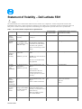
after power is removed from the component. The following NV components are present on the 5501’s system board.
Table 1. List of Non-Volatile Components on System Board
Description Reference Designator Volatility Description
User Accessible
for external data
Remedial Action (Action necessary
to prevent loss of data)
Panel
EEDID
EEPROM
Part of panel
assembly
Non-Volatile memory,
128bytes.
No
Part of panel assembly
System
BIOS
UC5(32MB)-Vpro
UC5(16MB)+UC6(8
MB)-Non Vpro
Non-Volatile memory,
System BIOS, embedded
controller and Video BIOS
for basic boot operation,
PSA (on board diags), PXE
diags.
No
Not Applicable
System
Memory –
DDR4
memory
Two SODIMM
connectors:
JDIMM1,2 present
Volatile memory in OFF
state
NOTE:
See state definitions
later in text.
One to Two modules must
be populated.
Yes
Power off system
System
memory
SPD
EEPROM
On System memory
SODIMM(s)
JDIMM1,2 present
Non-Volatile memory 512
Bytes.
Stores memory
manufacturer data and
timing information for
correct operation of system
memory.
No
Not Applicable
RTC
CMOS –
BBRAM
(battery
backed up)
UC1
Non-Volatile memory, 256
Bytes.
Stores CMOS information.
No Remove the onboard
coin cell
battery
Video
memory –
frame
buffer
For UMA platform:
using system DDR4
For DSC platform:
UV17, UV18
Volatile memory in off state.
UMA uses main system
memory size allocated out of
main memory.
Discrete graphics system
uses 2GB GDDR5.
No

October 2020
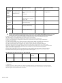
Description Reference Designator Volatility Description
User Accessible
for external data
Remedial Action (Action necessary
to prevent loss of data)
Security
Controller
Serial
Flash
Memory
U2 (up-sell USH
daughter board)
Non-Volatile memory, 128
Mbit
(16Mbyte)
No
Not Applicable
Hard
drive(s)
User replaceable
SSD (solid
State flash drive).
various
sizes in GB
Yes
Low level format
TPM
Controller
UZ12
Non-Volatile memory, 24K
bytes flash memory
No Not Applicable
TYPE C PD
controller
FW
UT6
Non-Volatile memory, 8M bits
(1M bytes) flash memory
No Not Applicable
Thunderbolt
controller
FW
UT2
Non-Volatile memory, 8M bits
(1M bytes) flash memory
No Not Applicable
CAUTION: All other components on the system board lose data if power is removed from the system. Primary power loss (unplugging
the power cord and removing the battery) destroys all user data on the memory (DDR4, 2400/2666 MHz). Secondary power loss
(removing the on-board coin-cell battery) destroys system data on the system configuration and time-of-day information.
In addition, to clarify memory volatility and data retention in situations where the system is put in different ACPI power
states the following is provided (those ACPI power states are S0, S1, S3, S4 and S5):
S0 state is the working state where the dynamic RAM is maintained and is read/write by the processor.
S1 state is a low wake-up latency sleeping state. In this state, no system context is lost (CPU or chip set) and hardware
maintains all system contexts.
S3 is called “suspend to RAM” state or stand-by mode. In this state the dynamic RAM is maintained. Dell systems will be
able to go to S3 if the OS and the peripherals used in the system supports S3 state. Win10 support S3 state.
S4 is called “suspend to disk” state or “hibernate” mode. There is no power. In this state, the dynamic RAM is not
maintained. If the system has been commanded to enter S4, the OS will write the system context to a non-volatile storage
file and leave appropriate context markers. When the system is coming back to the working state, a restore file from the nonvolatile
storage can occur. The restore file must be valid. Dell systems will be able to go to S4 if the OS and the peripherals
support S4 state. Win10 support S4 state.
S5 is the “soft” off state. There is no power. The OS does not save any context to wake up the system. No data will remain in
any component on the system board, i.e. cache or memory. The system will require a complete boot when awakened. Since
S5 is the shut off state, coming out of S5 requires power on which clears all registers.
The Following table shows all the states supported by Dell Latitude 5501:
Model Number
S0
S1
Modern
Standby
S4
S5
Dell Latitude
™
5501
X
X
X
X
______________
© 2013 Dell Inc.
Trademarks used in this text: Dell™, the DELL logo, Latitude™ are trademarks of Dell Inc. Intel®, Pentium®, Xeon®, Core™ and Celeron® are
registered trademarks of Intel Corporation in the U.S. and other countries. Microsoft®, Windows® are either trademarks or registered trademarks of
Microsoft Corporation in the United States and/or other countries.
-
 1
1
-
 2
2


em outras línguas
- English: Dell Latitude 5501 Reference guide
Artigos relacionados
-
Dell Precision 3541 Administrator Guide
-
Dell Latitude 5420 Guia rápido
-
Dell Precision 3551 Administrator Guide
-
Dell Latitude 5521 Administrator Guide
-
Dell Latitude 5511 Guia de usuario
-
Dell Precision 3561 Administrator Guide
-
Dell Latitude 5580 Administrator Guide
-
Dell Latitude 5480/5488 Guia de usuario
-
Dell Latitude 5280/5288 Guia de usuario
-
Dell Latitude 5590 Guia rápido