
Save this manual for future reference.
For more information, visit www.desatech.com
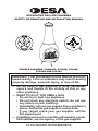
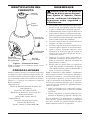
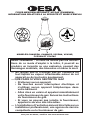
DECORATIVE GAS LOG CHIMENEA
SAFETY INFORMATION AND INSTALLATION MANUAL
MODELS CHAM55N, CHAM45P, VC55AN, VC45AP,
FC55AN AND FC45AP
WARNING: If the information in this manual is not fol-
— WHAT TO DO IF YOU SMELL GAS
• Do not touch any electrical switch; do not use
•
—
-

www.desatech.com
901918-01J2
-
-
SAFETY INFORMATION
chemicals known to the State
-
-
Early signs of
carbon monoxide poisoning resemble the u, with
headaches, dizziness, or nausea. If you have these
signs, the appliance may not be working properly.
Get fresh air at once! Have appliance serviced.
Some people are more affected by carbon monox-
ide than others. These include pregnant women,
people with heart or lung disease or anemia, those
under the inuence of alcohol, and those at high
altitudes.
Natural and
propane/LP gases are fuel gases. Fuel gases are
odorless. An odor-making agent is added to fuel
the gases. This odor helps you detect a fuel gas
leak. However, the odor added to fuel gas can
fade. Fuel gas may be present even though no
odor exists.
Make certain you read and understand all warnings.
Keep this manual for reference. It is your guide to
safe and proper operation of this appliance.
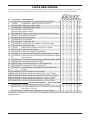
TABLE OF CONTENTS
Safety Information ............................................... 2
Product Identication ........................................... 5
Local Codes......................................................... 5
Unpacking............................................................ 5
Installation ........................................................... 6
Operating Appliance .......................................... 14
Cleaning and Maintenance ................................ 14
Technical Service............................................... 14
Troubleshooting ................................................. 15
Replacement parts ............................................ 16
Accessories ....................................................... 17
Parts Central...................................................... 17
Illustrated Parts Breakdown and Parts List........ 18
Warranty Information ......................................... 20

www.desatech.com
901918-01J 3
-
-
WARNING: Do not use
animals away from hot surface to
rock will remain hot for a time
SAFETY INFORMATION
Continued
WARNING: Do not allow
-
1. This appliance is only for use with the type
of gas indicated on the rating plate. If the
appliance must be converted for use with
propane/LP gas, a conversion kit model CA2
must be used. See Accessories, page 17.
2. The installation must conform with local codes
or, in the absence of local codes, with the Na-
tional Fuel Gas Codes ANSI Z223.1/NFPA 54
(U.S.) or CAN/CSA B149 Installation Codes
(Canada).
3. If you smell gas
• do not try to light any appliance
• do not touch any electrical switch; do not use
any phone in your building
• immediately call your gas supplier from a
neighbor’s phone. Follow the gas supplier’s
instructions
• if you cannot reach your gas supplier, call
the re department

www.desatech.com
901918-01J4
4. Keep the area around the appliance clear and
free from combustible materials, gasoline, or
other ammable vapors and liquids (i.e. trash,
yard debris or near garden sheds, car ports,
boats and motor homes).
5. Do not operate this appliance directly under
combustible materials such as trees, fabric or
vinyl awnings and patio covers.
6. Do not place this appliance on grass, near
shrubbery, or adjacent to draping such as
canvas tenting or vinyl tarps where they might
catch re.
7. Maintain proper clearances from combustible
materials (see Locating Appliance, page 6).
• Never place this appliance directly on any
combustible surface other than secure wood
construction (patio deck or open balcony).
Note: The chimenea will produce some soot-
ing. It is advisable to locate the chimenea away
from any overhanging.
8. Do not install this product in a partially
enclosed area such as a garage, car port,
screened in porch or recessed alcove where
accumulated heat and carbon monoxide can
result in a re or asphyxiation.
9. Do not place this appliance on an unstable or
uneven surface. This appliance must be placed
on a level and supported wood or noncombus-
tible surface only.
10. Do not operate this appliance where excessive
wind or drafts are present.
11. Locate supply line away from trafc areas
where people may trip over it or where it could
be accidentally damaged.
12. Inspect the exible supply line before each
use for signs or wear or damage, especially
near ttings. If the ex line shows excessive
wear or damage, replace the ex line assembly
before operating appliance.
13. Only use accessories listed on page 17 which
are approved for use with this appliance.
14. Do not use charcoal starting uid or any other
combustible uid to “help” ignite the re. This
could cause personal injury or death.
15. Do not burn solid fuel in this appliance.
SAFETY INFORMATION
Continued
16. Do not cook anything with this product. This
includes hot dogs, marshmallows, hamburg-
ers or any other food. Debris from food could
damage the burner system and affect its opera-
tion. Grease from food could ame up causing
severe burns or ignite clothing.
17. Do not burn anything in this product. Ashes
from trash or other combustibles could dam-
age the burner system and affect its operation.
Airborne ashes could set res elsewhere and
could cause severe burns or cause clothing to
ignite.
18.
Surfaces of this appliance can become extreme-
ly hot. Therefore, children and pets should be
carefully supervised when they are in the area
of this appliance. This appliance should not be
left unattended while it is operating.
19. Do not operate this product around intoxicated
people. They could injure themselves or others
when using this product.
20. Excessive exposure to water can damage the
hearth treatments. Water from rain, sprin-
klers, toys, horseplay, etc. can damage logs,
lava rock, and pan materials. To minimize
the effects of moisture on the burner system
and hearth treatments, an optional protective
cover, model CA1, is available for this appli-
ance when not in use (see Accessories, page
17). Make sure the appliance is cool before
using this cover.
21. Do not operate this appliance if any part has
been under water. Immediately call a qualied
service technician to inspect the appliance and
replace any part of the control system and any
gas control which has been under water.
22. Turn off gas at the main gas supply when this
appliance is not in use.
23. Turn appliance off and let cool before servic-
ing or repairing.
24. Do not operate this appliance without the
chimenea vent cap or base stand in place.
25. Use only original replacement parts as listed
on page 19. This appliance must use design-
specic parts. Do not substitute or use generic
parts. Using improper replacement parts could
cause serious or fatal injury and will void this
products warranty.
26. Do not locate propane/LP supply tanks below
ground or within 10 feet of the base of the
chimenea.

www.desatech.com
901918-01J 5
UNPACKING
WARNING: Do not remove
1. Carefully remove staples from top of outer
wrap carton. Open aps and remove upper
corrugated stabilizer.
2. Carefully remove clay cap from inside top and
set aside.
3. Remove staples from base of carton. Carefully
lift outer wrap over top of contents.
4. Lift clay top straight out of clay base and
carefully set aside.
5. Lift iron base stand over top of clay base.
6. Remove corrugated top support, and bags of
lava rock, vermiculite, glowing embers and
gas log set carton from inside base.
7. Remove logs, grate, burner, burner pan, and
connection kit from carton. Remove all protec-
tive packaging from logs.
8. Check all items for any shipping damage. If
damaged, promptly inform dealer where you
bought the product.
Note: Deterioration or damage due to severe
weather conditions such as hail, hurricanes,
earthquakes or tornadoes, or discoloration due
to exposure to chemicals either directly or in the
atmosphere, is not covered by the Limited War-
ranty on the back of this manual. The warranty
also does not cover the following:
• weather damage caused by not using the protec-
tive cover
• chips, cracks, or breakage caused from drop-
ping, dragging, or hitting chimenea.
The surface of the chimenea naturally contains
spaces, surface cracks and variations in color and
texture. The limited warranty does not cover such
surface imperfections.
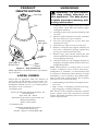
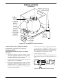
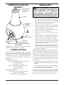
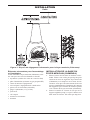
PRODUCT
IDENTIFICATION
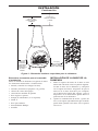
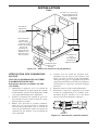
Figure 1 - Clay Chimenea
Note: Appearance of chimenea may vary depend-
ing on models.
LOCAL CODES
Install and use appliance with care. Follow all
local codes. In the absence of local codes, use
the latest edition of The National Fuel Gas Code,
ANSI Z223.1/NFPA 54 (U.S.)* or CAN/CSA B149
Installation Code (Canada)**.
*Available from:
American National Standards Institute, Inc.
1430 Broadway
New York, NY 10018
National Fire Protection Association, Inc.
Batterymarch Park
Quincy, MA 02269
**Available from:
Canadian Standards Association
178 Rexdale Boulevard
Toronto, Ontario, Canada M9W 1R3
Vent Cap
Top
Lighting
Port
Log Grate &
Burner Pan
Base
Stand
Manual
Gas Valve

www.desatech.com
901918-01J6
INSTALLATION
-
listed in these instructions may
-
warranty and may result in a
Check the rating plate to verify the type of gas your
appliance is equipped for use with. The rating plate
can be found on the metal instruction tag attached
to the chimenea burner pan. If your appliance is
not equipped for the supply gas available, call
the dealer where you purchased the chimenea to
obtain a properly equipped model or an approved
conversion kit for your type of gas supply.
Propane/LP gas versions are supplied with a two
stage external regulator with a 10 foot (3 m) hose
assembly for ready connection to a properly sized,
(DOT or CAN/CSA B339) approved propane/LP
supply tank. This tank can be purchased from
your propane/LP or builder supplier. See Sizing
Propane/LP Supply Tank, page 10.
Natural gas versions must be provided with an
equipment shutoff valve installed in the supply
line upstream of the manual control valve provided
with the chimenea. A model GA5010 gas equip-
ment shutoff valve with a 1/8" NPT pressure tap
may be purchased through your dealer. See Con-
necting to Natural Gas Supply, page 9.
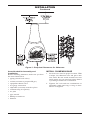
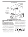
When locating this appliance, follow all safety
information on pages 2 through 4.
Do not use this appliance indoors. It is for outdoor
use only. When locating this appliance under wood
or noncombustible overhangs, the chimenea cap
must be in place and the specied clearances must
be maintained (see Figure 2, page 7).
Any types of materials other than wood or non-
combustible masonry surfaces could be damaged
or set on re.
Maintain proper clearances from combustible
materials.
• Make sure combustible materials such as trees
and fabrics are at least 10 feet (3 m) above the
chimenea cap.
• Maintain a minimum of 4 feet (1.3 m) of
clearance between the top of the vent cap and
any overhead combustible material (second
story balcony or deck, patio overhang such as
uncovered lattice or lanai).
Note: The chimenea will produce some sooting.
It is advisable to locate the chimenea away from
any overhanging.
• Make sure all combustible materials such as
shrubs, furnishings, and fabrics are at least
36" (1 m) from the sides and in front of the
chimenea opening.
• Maintain a minimum 12" (30 cm) clearance
from the widest point on the sides and back of
chimenea base to any combustible materials
such as wood, vinyl siding, or masonry con-
struction, and 36" (1 m) in front of the chimenea
opening.
Make sure to locate appliance, gas hose, and rigid
supply lines out of trafc areas to prevent tripping
and accidental damage to the chimenea and supply
connections.

www.desatech.com
901918-01J 7
Figure 2 - Required Clearances for Chimenea
INSTALLATION
Continued
Installation
Before installing chimenea, make sure you have
the items listed below.
• piping (check local codes)
• sealant (resistant to propane/LP gas)
• equipment shutoff valve
• test gauge connection
• adjustable (crescent) wrench or pliers
• sediment trap (if required)
• tee joint
• pipe wrench
• Phillips screwdriver
• hammer
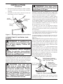
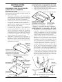
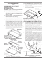
1. Set iron base stand in proper location. With
a helper, lift chimenea base and place onto
iron stand. Be sure notch around base rests
inside entire ring on stand and clamp xture
is pointing towards rear of chimenea.
2. Tighten 3/8" bolt and nut combination on
adjustable stand until ring is snug on base.
Do not overtighten.

www.desatech.com
901918-01J8
INSTALLATION
Continued
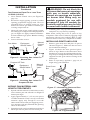
INSTALLATION
Note: Be sure all pipe thread connections are tight,
and have thread compound to prevent leaks.
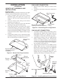
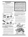
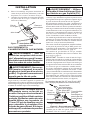
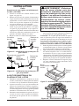
1. Using a hammer and screw driver, remove
knockout plug from right side of pan (see
Figure 3). Do not remove plug from left side
of pan.
2. Unscrew burner inlet fitting from burner
manifold (see Figure 4).
3. Place burner manifold in pan with threaded
opening facing open knockout plug.
4. Using thread sealant (resistant to the action
of propane/LP gas) on larger end of tting,
screw burner inlet tting through hole and into
burner manifold until ange on tting is fully
seated in knockout hole. Tighten fully using a
wrench.
5. Using burner clamp, screw, and nut provided,
assemble clamp over front end of U-burner.
This will hold burner manifold in place.
Figure 3 - Knock-Out Plug Locations
Knock-Out
Plugs
Burner
Clamp
Burner
Pan
Burner Pan Assembly
(Facing Front of
Fireplace)
Figure 4 - Installing Burner
Nut
Screw
Burner
Manifold
Burner
Inlet
Fitting
1.
Thread inlet elbow tting to burner inlet
tting
.
2. Attach lose end of ex connector to inlet elbow
tting.
Figure 5 - Connecting Gas to Appliance
Burner Pan Assembly
(Facing Front of Fireplace)
Inlet Elbow
Fitting
Gas Connector
Tube
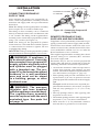
1. Assemble bulkhead tting with ange plates
and tting nut. Tighten nut snugly using an
adjustable wrench, (see Figure 6). Do not
overtighten as this may break the clay base.
2. Apply thread sealant to the 3/8" MPT thread
end of manual control valve. Thread into
outside of bulkhead tting with adjustable
wrench. Use wrench on outer bulkhead tting
to avoid spinning the tting and overtighten-
ing assembly (see Figure 6).
3. Apply thread sealant to the 3/8" MPT of are
tting. With an 11/16" wrench, thread pipe
thread end of are tting into rear bulkhead
tting from inside chimenea (see Figure 7,
page 9). Be sure to use a wrench on the 1
1
/
8
"
outside hex nut of bulkhead tting to avoid
spinning the tting or damaging clay base.
Bulkhead Fitting
Flange
Plates
Manual
Control
Valve
Figure 6 - Installing Manual Control Valve

www.desatech.com
901918-01J 9
4. Place burner pan assembly in center of chime-
nea oor with front of pan facing chimenea
opening.
5. Attach loose end of ex connector to the 3/8"
are tting at rear of chimenea.
INSTALLATION
Continued
Figure 7 - Installing Manual Control Valve
Bulkhead
Fitting
Flare
Fitting
11/16"
Wrench
SUPPLY
-
WARNING: Never connect
IMPORTANT: Check gas line pressure before
connecting heater to gas line. Gas line pressure
must be within the range of pressure specied in
Figure 9, page 10. If gas line pressure is higher,
damage to the control valve could occur.
-
For natural gas units, a minimum 1/2" (13 mm)
diameter or greater rigid black iron supply line
must be provided down stream from gas meter and
at above ground location of outdoor appliance.
Special code provisions apply to outdoor piping
when installed above ground and underground. All
outdoor gas piping must be installed and protected
in accordance with local code and in absence of
local code with Part 3 of the National Fuel Gas
Codes ANSI Z223.1/NFPA 54 (U.S.) or CAN/CSA
B149 Installation Codes (Canada).
A flexible gas line and an equipment shutoff
valve with pressure test point must be provided
upstream of manual control valve provided with
the chimenea.
A model GA5010 equipment shutoff valve with a
1/8" NPT pressure tap may be purchased through
your dealer. See Accessories, page 17.
A model GA5080 3/8" exible supply line may be
purchased through your dealer. See Accessories,
page 17.
IMPORTANT: Install equipment shutoff valve at
an accessible point in the supply line ahead of the
exible connection. The equipment shutoff valve
is for shutting off the gas to the appliance when
a leak occurs between the supply connection and
the manual control valve.
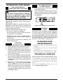
Codes require that a 3" (77 mm) minimum drip
leg or sediment trap be installed in the supply line
nearest the inlet of the appliance. If not already
provided at the outlet of gas meter, check with
local codes as to whether a drip leg or sediment
trap need be provided (see Figure 8).
Figure 8 - Gas Connection
* Purchase the optional CSA design-certified
equipment shutoff valve from your dealer. See
Accessories, page 17.
3" (7.7 mm)
Minimum
Sediment Trap
From Gas Meter [5" (127 mm) W.C.
to 10.5" (267 mm) W.C. Pressure]
CSA Design-Certied
Equipment Shutoff Valve
With 1/8" NPT Tap*
Approved
Flexible Gas
Hose (if allowed
by local codes)
Cap Pipe Tee
Nipple Joint

www.desatech.com
901918-01J10
INSTALLATION
Continued
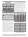
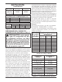
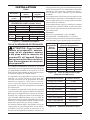
Figure 9 - Technical Information Charts
Size
Natural
18" 0.120 31 0.073 49
FUEL INLET PRESSURE
Min. Max.
NG 5.5" (140 mm) 10.5" (267 mm)
LP 11" (280 mm) 13" (330 mm)
Natural Gas
18" Dual
Burner
55,000 45,000
-
Connect-
ing Propane/LP Supply Tank
The models CHAM45P, FC45AP and VC45AP
are supplied with a two stage, propane/LP regu-
lator and 10 foot (3 m) hose assembly ready for
connection to 3/8" are tting at inlet of manual
control valve.
The propane/LP regulator is factory set at 11"
(280 mm) w.c. and can be connected to a properly
sized and approved propane/LP supply tank. This
supply tank can be purchased from your propane/
LP or builder supplier.
The propane/LP cylinder used must be constructed
and marked as (DOT or CAN/CSA B339) ap-
proved for vapor withdrawal and equipped with a
safety relief type ON/OFF valve with a protective
collar. The propane/LP cylinder must be sized
according to the input rate and expected ambient
temperature of fuel in container.
The rst table (Figure 10) indicates the vaporiza-
tion rate of propane/LP fuel at various Btu/Hr input
rates for a range of cylinder sizes and ambient fuel
temperatures. An undersized or under lled pro-
14.1 oz (0.4 kg) 19,000
16.4 oz (0.5 kg) 22,100
5 lb (2.3 kg) 107,800
10 lb (4.5 kg) 215,600
20 lb (9.1 kg) 431,200
100 lb (45 kg) 2,156,000
250 gal (946 L) 22,875,000
500 gal (1900 L) 45,750,000
1000 gal (3790 L) 91,500,000
Pounds of
in cylinder
0° F
(-17.8° C)
20° F
(-6.7° C)
40° F
(4.4° C)
100 113,000 167,000 214,000
90 104,000 152,000 200,000
80 94,000 137,000 180,000
70 83,000 122,000 160,000
60 75,000 109,000 140,000
50 64,000 94,000 125,000
40 55,000 79,000 105,000
30 45,000 66,000 85,000
20 36,000 51,000 68,000
10 28,000 38,000 49,000
Figure 10 - Vaporization Rate (per 100
pound cylinder)
Figure 11 - Maximum Btu Content
pane/LP tank, when evacuating at lower outdoor
temperatures, can cause a condition known as “va-
por lock” to occur. Vapor lock prevents vaporized
fuel from reaching the burner system.
It is important to use a cylinder size based on an
input rate higher than 45,000 Btu/Hr at the lowest
expected outdoor ambient temperature to insure
vaporization of fuel.
The second table (Figure 11) indicates the maxi-
mum Btu content of a full cylinder and can be used
to calculate the approximate operating hours.
Example:
20 pounds propane/LP = 431,200 Btu’s
431,200 Btu ÷ 45,000 Btu/Hr = 9.5 Hours
Actual operating hours may vary depending on
outdoor temperature and ll quality of tank.

www.desatech.com
901918-01J 11
COUNTER-CLOCKWISE
TO TIGHTEN
INSTALLATION
Continued
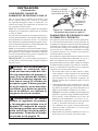
After obtaining the proper size propane/LP cyl-
inder, connect regulator/hose assembly between
chimenea and supply tank valve per instructions
that follow.
Note: The ttings on the regulator/hose assembly
do not require use of sealant or Teon tape.
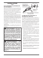
The tting on hose assembly can be connected
directly to manual control valve on chimenea with
a 3/4" wrench. The tting on the regulator/hose
assembly can be connected to propane/LP cylinder
using a 7/8" wrench (see Figure 12).
Note: The fitting on the propane/LP cylinder
connection has a left hand thread which requires
a counterclockwise motion to tighten. Do not
overtighten this tting.
IMPORTANT: The gas at the propane/LP cylinder
must be turned off when appliance is not in use.
-
outdoors in a well-ventilated
Figure 12 - Connecting Propane/LP
Supply Tank
Regulator/Hose
Assembly
REMOTE PROPANE/LP GAS
If appliance is to be permanently connected to a gas
piping system from a remote supply tank, installa-
tion must be in accordance with local codes or, in
absence of local codes, with the National Fuel Gas
Codes ANSI Z223.1/NFPA 54 (U.S.) or CAN/CSA
B149 Installation Codes (Canada).
The supplied regulator/hose assembly has a xed
pressure setting at 11" (280 mm) W.C. and must
be used at supply tank.
Enclosures may be used to conceal propane/LP
supply tanks and must be constructed to meet the
following minimum construction requirements:
• An enclosure must have either one open side or
at least four opposing vent openings, top and
bottom, which meet minimum requirements for
size and location (see Figure 13, page 12).
• Each opening must provide a minimum or 1/2
square inches (3,23 cm
2
) of open area for each
pound propane/LP contained in enclosed supply
tank.
Example: A full enclosure for a 20 pound pro-
pane/LP tank must have at least four, 10 square
inch (65 cm
2
) openings [a 2" x 5" (5 x 13 cm)
square].
• The top openings must be 180° opposing and
be placed at valve level.
•
The bottom openings must be 180° opposing and
be placed 5" (12.7 cm) above bottom oor.
• There must be 2" (5 cm) minimum clearance
from the oor to ground level of enclosure

www.desatech.com
901918-01J12
Figure 13 - Propane/LP Tank Enclosure
Minimum of 5" (12.7 cm)
From Floor To Top Of
Bottom Opening
Minimum of
2" (5 cm)
From Floor
Bottom To
Ground Level
Minimum 1/8"
(0.3 cm)
Permissible
Openings
Top
Openings
At Valve
Level
2 Openings
Top and
Bottom on
Each Side
Minimum
0.5 inch
2
(3.23 cm
2
)
of Free Air
Space For
Each Pound
of Fuel But No
Less Than
10 inches
2
(65 cm
2
) Total
INSTALLATION
Continued
PRESSURE TESTING GAS SUPPLY
PIPING SYSTEM
1.
Disconnect appliance with its manual control
valve and equipment shutoff valve from gas sup-
ply piping system. Pressures in excess of 1/2 psig
(3.5 kPa) will damage heater regulator.
2. Cap off open end of gas pipe where equipment
shutoff valve was connected.
3. Pressurize supply piping system by either
opening propane/LP supply tank valve for
propane/LP gas or opening main gas valve
located on or near gas meter for natural gas,
or using compressed air.
4. Check all joints of gas supply piping system,
for natural gas see Figure 15, page 13 or for
propane/LP gas, see Figure 16, page 13. Ap-
ply commercial leak detection solution to gas
joints. Bubbles forming show a leak.
5. Correct all leaks at once.
6. Reconnect heater and equipment shutoff valve
to gas supply. Check reconnected ttings for
leaks.
Figure 14 - Manual Control Valve

www.desatech.com
901918-01J 13
Propane/LP Tank
Equipment
Shutoff Valve
Manual
Control
Valve
Figure 15 - Checking Gas Joints For
Natural Gas
Gas Meter
Equipment
Shutoff Valve
Figure 16 - Checking Gas Joints For
Propane/LP Gas
Manual
Control
Valve
1. Close manual control valve (see Figure 14,
page 12).
2. Pressurize supply piping system by either
opening propane/LP supply tank valve for
propane/LP gas or opening main gas valve
located on or near gas meter for natural gas,
or using compressed air.
3. Check all joints of gas supply piping system,
for natural gas see Figure 15 or for propane/LP
gas, see Figure 16. Apply commercial leak de-
tection solution to gas joints. Bubbles forming
show a leak.
4. Correct all leaks at once.
INSTALLATION
Continued
ADDING PAN MATERIAL AND
HEARTH TREATMENTS
1. Spread ash bed material (vermiculite) evenly
across burner pan and smooth it to height of
burner pan edges.
2. Apply approximately 1" (2.5 cm) size pieces
of ember material evenly over top of ash bed
material. Apply only enough to cover the
entire surface area of the pan. Applying exces-
sive amounts will only diminish the glowing
effect of the embers.
3.
Spread lava rock evenly around front and sides of
burner pan. Do not place lava rock inside pan.
4. Carefully place clay top onto chimenea base
and place clay cap into top opening.
Note: Some sooting may occur at joints of clay
components. This can be avoided by applying a high
temperature silicone based caulking (RTV or other)
between surfaces where clay components assemble.
INSTALLING GRATE AND LOGS
1. Remove grate from box and place in pan as
shown in Figure 17. Make sure the rear cross
bar is behind rear ange.
2. Figure 18 shows the most practical place-
ment of logs. Refer to the Illustrated Parts
Breakdown on page 18 to distinguish each log.
Logs may be arranged differently, but must be
supported on the grate and not resting in the
burner pan.
3. Refer to Operating Appliance, page 14, to
begin using your chimenea.
b
d
f
a
c
e
Figure 17 - Assembling Grate and Pan
Figure 18 - Log Placement
Rear Cross
Bar
Rear
Flange

www.desatech.com
901918-01J14
Figure 19 - Manual Control Valve
OPERATING APPLIANCE
FOR YOUR SAFETY
WARNING: If you do not fol-
low these instructions exactly,
-
This appliance must be lit by hand. When
lighting this appliance, follow these instruc-
tions exactly.
BEFORE LIGHTING smell all around the
appliance area for gas. Be sure to smell next to
the oor because some gas is heavier than air
and will settle on the oor.
WHAT TO DO IF YOU SMELL GAS
• Do not try to light any appliance.
• Do not touch any electric switch; do not use
any phone in your building.
• Immediately call your gas supplier from a
neighbor’s phone. Follow the gas supplier’s
instructions.
• If you cannot reach your gas supplier, call
the re department.
LIGHTING
1.
STOP! Read the safety information, above.
2. Turn the manual control valve to OFF.
3. Wait ve (5) minutes to clear any gas. If
you then smell gas STOP! Follow the safety
information above. If you don’t smell gas,
go on to the next step.
4.
Extend a butane lighting wand through light-
ing access hole, or place a burning match on
top of pan material about 2" (5 cm) from end
of supply side of pan. Do not hold match in
your hand.
5. Slowly turn manual control valve counter-
clockwise to the ON position until
burner ignites. If burner does not ignite
within 10 seconds or before match goes
out, turn manual control valve clockwise
to the OFF position and repeat steps
2 through 5 again.
TO TURN OFF GAS
1. Turn manual control valve clockwise
to the OFF position.
2. Close propane/LP supply tank valve, dis-
connect regulator hose and plug supply
tank during seasonal nonuse or when stor-
ing appliance.
LOGS
During the 2-3 hour appliance break-in period,
you may detect an odor from the appliance
as various paints and compounds used in the
manufacturing of this log set cure. This is a nor-
mal and temporary situation that is not cause
for alarm. You may want to let unit burn for a
period of 1 hour before occupying area.
CLEANING AND
MAINTENANCE
• Keep area around the chimenea clean and clear
of debris.
• Occasionally, you may use a soft bristle brush
to clean logs.
• Periodically check ventilation holes in chime-
nea cap and remove any obstructions found.
TECHNICAL SERVICE
You may have further questions about instal-
lation, operation, or troubleshooting. If so,
contact DESA’s Technical Service Department
at 1-866-672-6040. When calling, please have
your model and serial numbers of your heater
ready.
You can also visit DESA’s technical service web
site at .

www.desatech.com
901918-01J 15
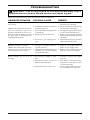
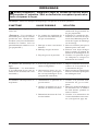
TROUBLESHOOTING
Note: All troubleshooting items are listed in order of operation.
1. Poor fuel quality
2. Chimenea venting system not
drafting properly
3. Excessive ame impingement
or blockage
4. Improper fuel/air mixture
5. Excessive gas supply/pres-
sure
1. Passage of air/gas across ir-
regular surfaces
2. Obstructions in the primary air
openings of air mixer tting
(propane/LP only)
1. Incorrect gas supply or pres-
sure
2. Blocked burner orifice or
burner manifold ports
3. Improper burner orice size
REMEDY
1. Contact local natural or pro-
pane/LP gas company
2. Inspect chimenea vent and cap
for damage or blockage
3.
Arrange the logs to allow ame
to pass in between the logs
4. Remove any foreign items in
and around the burner pan and
air mixer
5. Check for proper gas pressure
and correct orice size
1. Relieve any tight bends or
kinks in gas supply lines
2. Remove any obstructions in
primary air mixer openings
1. Check for proper gas supply
pressure
2. Free burner orice and mani-
fold ports of any burrs, paint,
or other blockage
3.
Verify proper burner orice siz-
ing (see Figure 10, page 10)
Log set is smoking/sooting
excessively
(Note: It is natural and unavoid-
able for vented gas log sets to
produce moderate levels of car-
bon (soot) where ames contact
the logs. This is especially true
with propane/LP gas.)
Burner is excessively noisy
(Note: The movement and com-
bustion of gas will create low,
unavoidable levels of noise.)
Burner ames are too low or
too high

www.desatech.com
901918-01J16
REPLACEMENT PARTS
Note: Use only original replacement parts. This
will protect your warranty coverage for parts
replaced under warranty.
PARTS UNDER WARRANTY
Contact authorized dealers of this product or Parts
Central (see page 12). If they can’t supply original
replacement part(s), call DESA’s Technical Service
Department at 1-866-672-6040.
When calling DESA, have ready
• your name
• your address
• model and serial numbers of your replace
• how the chimenea was malfunctioning
• type of gas used (propane/LP or natural gas)
• purchase date
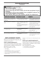
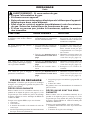
-
1.
Metal expanding while heating
or contracting while cooling
1. Log set burning vapors from
paint, or other outdoor con-
taminants
2. Gas leak. -
1. Gas leak. -
2. Control valve defective
1. Gas leak. -
Log set produces a clicking/tick-
ing noise just after burner is lit
or shut off
Log set produces unwanted
odors
Gas odor even when control knob
is in OFF position
Gas odor during combustion
REMEDY
1. This is common with most log
sets. If noise is excessive, con-
tact qualied service person
1.
Do not operate until paint and other
volatile compounds have been
properly cured or evacuated
2. Locate and correct all leaks
(see Checking Gas Connec-
tions, page 12)
1. Locate and correct all leaks
(see Checking Gas Connec-
tions, page 12)
2. Replace control valve
1. Locate and correct all leaks
(see Checking Gas Connec-
tions, page 12)
TROUBLESHOOTING
Continued
Usually, we will ask you to return the part to the
factory.
PARTS NOT UNDER WARRANTY
Contact authorized dealers of this product or Parts
Central (see page 17). If they can’t supply original
replacement part(s), call DESA at 1-866-672-6040
for referral information.
When calling DESA, have ready
• model number of your chimenea
• the replacement part number

www.desatech.com
901918-01J 17
PARTS CENTRAL
These Parts Centrals are privately owned business-
es. They have agreed to support our customer’s
needs by providing original replacement parts
and accessories.
5 Manila Ave
Hamden, CT 06514-0322
1-800-397-7553
203-248-7553
342 N. County Rd. 400 East
Valparaiso, IN 46383-9704
219-462-7441
1-888-619-7060
www.portableheaterparts.com
1349 Adams Street
Bowling Green, KY 42103-3414
270-846-1199
1-800-654-8534
Fax: 1-800-846-0090
1251 Mound Ave. NW
Grand Rapids, MI 49504-2672
616-791-0505
1-800-446-1446
www.nbmc.com
1715 Main Street
Kansas City, MO 64108-2195
KS, MO, AR
816-842-3911
www.washerparts.com
707 Broadway
W. Long Branch, NJ 07764-1501
732-870-8809
1-800-755-8809
www.njplaza.com/ecep
2950 Fretz Valley
Perkasie, PA 18944-4034
215-795-0400
800-325-4828
2444 N. 5th Street
Hartsville, SC 29550-7704
843-332-0191
Parts Department
P.O. Box 645
Taylor, SC 29687-0013
803-879-3009
1-800-845-5301
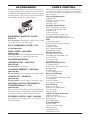
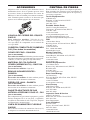
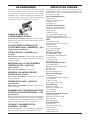
EqUIPMENT SHUTOFF VALVE
For all models. Equipment shutoff valve with
1/8" NPT tap. Fits 1/2" NPT pipe.
For all models. Use for additional decoration only.
Carton of 6 Boxes (3 pine cones per box).
For all models. Carton of 6.
For all models. Use for rebox decoration only.
For all models. Use for rebox decoration only.
NATURAL GAS TO PROPANE/LP
For conversion from natural gas to propane/LP gas.
Includes 10' hose and regulator, air mixer/injector
assembly, conversion label and instructions.
For connection to supply line. 12" (30 cm) ts
3/8" are tting
ACCESSORIES
Purchase these replace accessories from your lo-
cal dealer. If they can not supply these accessories,
call DESA’s Sales Department at 1-866-672-6040
for information. You can also write to the address
listed on the back page of this manual.

www.desatech.com
901918-01J18
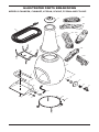
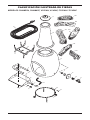
ILLUSTRATED PARTS BREAKDOWN
3
3
1
10
18
15
16
17
22a
22b
22c
22d
22e
22f
11
13
20
19
12
9
6
4
4
2
14
21
5
7
8

www.desatech.com
901918-01J 19
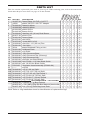
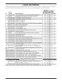
PARTS LIST
This list contains replaceable parts used in your log set. When ordering parts, follow the instructions
listed under Replacement Parts on page 16 of this manual.
qTY
1 901057-01 Brass Elbow 3/8 FLR x 3/8 FPT • • • • • • 1
2 14500 Brass 3/8 FLR x 3/8 FPT Adapter • • • • • • 1
3 901066-01 Brass Air Mixer • • • 1
901066-02 Brass Air Mixer • • • 1
4 901064-02 Brass Orice • • • 1
901065-02 Brass Orice • • • 1
5 901209-01 Manifold 18" (46 cm) Dual Burner • • • • • • 1
6 901137-01 Burner Pan • • • • • • 1
7 901681-01 Burner Strap • • • • • • 1
8 901078-01 Nut #8/32 • • • • • • 1
9 901076-01 Screw #8/32 x 3/8 • • • • • • 1
10 101628-01 Gas Line - 10" (25 cm) Flex • • • • • • 1
11 901081-01 Gas Valve • • • • • • 1
12 11214 Brass Bulkhead Fitting w/ Nut • • • • • • 1
13 901931-01 Bulkhead Plate • • • • • • 2
14 901244-01 Log Grate • • • • • • 1
15 901922-01 Clay Chimenea Base • • • • • • 1
16 901932-01 Clay Chimenea Top (Chimney) • • • • • • 1
17 901933-01 Clay Chimenea Cap • • • • • • 1
18 901923-01 Wrought Iron Base/Stand • • • • • • 1
19 901074-02 Bolt 1/4-20 x 1.25 Hex Black Oxide • • • • • • 1
20 901083-01 Nut 1/4-20 Hex Black Oxide • • • • • • 1
21 LPA3100 Regulator Hose Assembly (079060-04) • • • 1
22
____
Log Kit • • • • • • 1
22A 901842-01 Log, 8" (20 cm) Split • • • • • • 1
22B 901092-01 Log, Top 13.5" (34 cm) Split • • • • • • 1
22C 901844-01 Log, 10" (25 cm) Top Round Y • • • • • • 1
22D 901845-01 Log, Firepit 10" (25 cm) Split • • • • • • 1
22E 901840-01 Log, Firepit 7" (18 cm) Round • • • • • • 1
22F 901843-01 Log, Firepit 9" (23 cm) Split • • • • • • 1
901156-01 0.125 lb. (57 g) Bag Embers • • • • • • 1
901155-01
1.5 lb. (680 g) Bag Ash Bed Material (Vermiculite)
• • • • • • 1
901157-02 8 lb. (3.6 kg) Plain Bag Lava Rock • • • • • • 1
Note: Refer to Log Installation sheet for identication of replacement logs

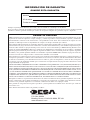
LIMITED WARRANTY
DESA warrants this product to be free from defects on burner system and logs for one (1) year from the date of rst
purchase, provided that the product has been properly installed, operated and maintained in accordance with all ap-
plicable instructions. To make a claim under this warranty the Bill of Sale or cancelled check must be presented.
This warranty is extended only to the original retail purchaser. This warranty covers the cost of part(s) required to
restore this log set to proper operating condition and an allowance for labor when provided by a DESA Authorized
Service Center. Warranty part(s) MUST be obtained through authorized dealers of this product and/or DESA who
will provide original factory replacement parts. Failure to use original factory replacement parts voids this war-
ranty. The log set MUST be installed by a qualied installer in accordance with all local codes and instructions
furnished with the unit.
This warranty does not apply to parts that are not in original condition because of normal wear and tear, or parts
that fail or become damaged as a result of misuse, accidents, lack of proper maintenance or defects caused by
improper installation. Travel, diagnostic cost, labor, transportation and any and all such other costs related to
repairing a defective log set will be the responsibility of the owner.
TO THE FULL EXTENT ALLOWED BY THE LAW OF THE JURISDICTION THAT GOVERNS THE SALE
OF THE PRODUCT; THIS EXPRESS WARRANTY EXCLUDES ANY AND ALL OTHER EXPRESSED
WARRANTIES AND LIMITS THE DURATION OF ANY AND ALL IMPLIED WARRANTIES, INCLUD-
ING WARRANTIES OF MERCHANTABILITY AND FITNESS FOR A PARTICULAR PURPOSE TO ONE
(1) YEAR ON BURNER SYSTEM AND LOGS FROM THE DATE OF FIRST PURCHASE; AND DESA’S
LIABILITY IS HEREBY LIMITED TO THE PURCHASE PRICE OF THE PRODUCT AND DESA SHALL
NOT BE LIABLE FOR ANY OTHER DAMAGES WHATSOEVER INCLUDING INDIRECT, INCIDENTAL
OR CONSEQUENTIAL DAMAGES.
Some states do not allow a limitation on how long an implied warranty lasts or an exclusion or limitation of
incidental or consequential damages, so the above limitation on implied warranties, or exclusion or limitation on
damages may not apply to you.
This warranty gives you specic legal rights, and you may also have other rights that vary from state to state.
For information about this warranty write:
WARRANTY INFORMATION
KEEP THIS WARRANTY
Always specify model and serial numbers when communicating with the factory.
We reserve the right to amend these specications at any time without notice. The only warranty applicable is our
standard written warranty. We make no other warranty, expressed or implied.
2701 Industrial Drive
P.O. Box 90004
Bowling Green, KY 42102-9004
www.desatech.com
Model
Serial No.
Date Purchased
A página está carregando...
A página está carregando...
A página está carregando...
A página está carregando...
A página está carregando...
A página está carregando...
A página está carregando...
A página está carregando...
A página está carregando...
A página está carregando...
A página está carregando...
A página está carregando...
A página está carregando...
A página está carregando...
A página está carregando...
A página está carregando...
A página está carregando...
A página está carregando...
A página está carregando...
A página está carregando...
A página está carregando...
A página está carregando...
A página está carregando...
A página está carregando...
A página está carregando...
A página está carregando...
A página está carregando...
A página está carregando...
A página está carregando...
A página está carregando...
A página está carregando...
A página está carregando...
A página está carregando...
A página está carregando...
A página está carregando...
A página está carregando...
A página está carregando...
A página está carregando...
A página está carregando...
A página está carregando...
-
 1
1
-
 2
2
-
 3
3
-
 4
4
-
 5
5
-
 6
6
-
 7
7
-
 8
8
-
 9
9
-
 10
10
-
 11
11
-
 12
12
-
 13
13
-
 14
14
-
 15
15
-
 16
16
-
 17
17
-
 18
18
-
 19
19
-
 20
20
-
 21
21
-
 22
22
-
 23
23
-
 24
24
-
 25
25
-
 26
26
-
 27
27
-
 28
28
-
 29
29
-
 30
30
-
 31
31
-
 32
32
-
 33
33
-
 34
34
-
 35
35
-
 36
36
-
 37
37
-
 38
38
-
 39
39
-
 40
40
-
 41
41
-
 42
42
-
 43
43
-
 44
44
-
 45
45
-
 46
46
-
 47
47
-
 48
48
-
 49
49
-
 50
50
-
 51
51
-
 52
52
-
 53
53
-
 54
54
-
 55
55
-
 56
56
-
 57
57
-
 58
58
-
 59
59
-
 60
60


em outras línguas
- español: FMI cham45p El manual del propietario
- français: FMI cham45p Le manuel du propriétaire
- English: FMI cham45p Owner's manual
Outros documentos
-
HeatStar HS170FAVT Manual do proprietário
-
-
Mr. Heater MH18CH Manual do proprietário
-
-
-
-
Desa 125-R Manual do usuário
-
-
Thermador PALPKITHW5 Guia de instalação
-