


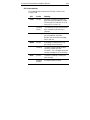
Scorpion 240 DDS-4 Autoloader
Installation Manual
Section A
English

© 2000 Seagate Removable Storage Solutions, LLC. All rights reserved
Part Number 100135972
Seagate and the Seagate logo are registered trademarks of Seagate
Technology, LLC. Scorpion 240 and the Scorpion logo are either
trademarks or registered trademarks of Seagate Removable Storage
Solutions LLC. Other product names are registered trademarks or
trademarks of their owners.
Seagate reserves the right to change, without notice, product offerings or
specifications. No part of this publication may be reproduced in any form
without written permission from Seagate Removable Storage Solutions.
Publication Number: 10007066-003, November 13, 2000

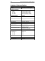
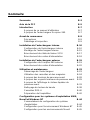
Contents
Contents A-3
FCC notice A-5
Introduction A-7
About this user’s guide A-7
About the Scorpion 240 autoloader A-7
Before you begin A-9
Precautions A-9
Unpacking and inspection A-9
Installing the internal autoloader A-10
Configuring the internal autoloader A-10
Mounting the internal autoloader A-15
Connecting the SCSI interface cable A-16
Connecting a power cable A-17
Installing the external autoloader A-18
Configuring the external Scorpion 240 A-18
Connecting the power cord A-20
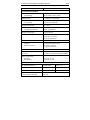
Operation and maintenance A-21
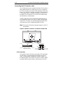
Starting the autoloader A-21
Using cartridges and magazines A-22
About the front-panel buttons A-26
About the front-panel LEDs A-27
About the front-panel LCD display A-30
Cleaning the tape drive A-34
DDS-4 cartridge information A-37
Preparation for shipping A-38
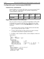
Configuration for UNIX, Novell, and Windows NT
operating systems A-40
Operating-system configuration dip switches A-40
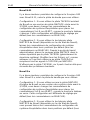
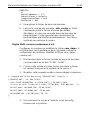
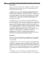
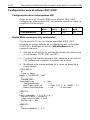
Configuration for the Windows NT environment A-41
Configuration for Novell environments A-41
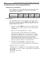
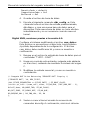
Configuration for the DEC UNIX environment A-43
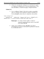
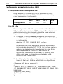
Configuration for the Sun UNIX environment A-45

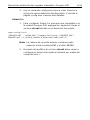
Configuration for the SGI environment A-47
Configuration for the HP-UX environment A-51
Configuration for the IBM AIX environment A-52
Configuration for SCO UNIX A-53
Configuration for LINUX A-53
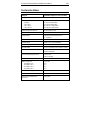
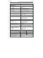
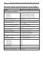
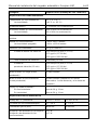
Summary of drive specifications A-54
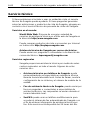
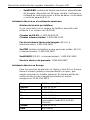
Support services A-56

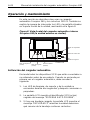
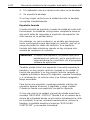
FCC notice
This equipment generates and uses radio frequency energy and, if not
installed and used in strict accordance with the manufacturer's
instructions, may cause interference to radio and television reception,
which could void the user's authority to operate the equipment. It has been
tested and found to comply with the limits for a Class B digital device
pursuant to Part 15 of FCC Rules, which are designed to provide
reasonable protection against such interference in a residential installation.
However, there is no guarantee that interference will not occur in a
particular installation. If interference does occur, try to correct it by taking
one or more of the following measures:
•
Reorient or relocate the receiving antenna.
•
Increase the separation between the computer and the receiver.
•
Connect the computer into an outlet on a circuit different from that to
which the receiver is connected.
•
Consult the dealer or an experienced radio/television technician for
help.
You may find the following booklet prepared by the Federal
Communications Commission helpful:
How to Identify and Resolve Radio–
TV Interference Problems.
This booklet (Stock No. 004-000-00345-4) is
available from the U.S. Government Printing Office, Washington, DC
20402.
This equipment complies with the limits for Class B digital apparatus in
accordance with Canadian Radio Interference Regulations.
Cet appareil numérique de la classe B est conforme au Règlement sur
brouillage radioélectrique, C. R. C., ch. 1374.

Scorpion 240 Autoloader Installation Manual A-7
Introduction
About this user’s guide
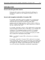
This user’s guide contains information on installing and
operating the Scorpion 240 DDS-4 autoloader.
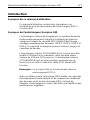
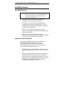
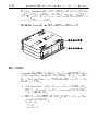
About the Scorpion 240 autoloader
The Seagate internal Autoloader is a fully integrated,
intelligent, multicartridge tape system that supports the DDS
(Digital Data Storage), DDS-1, DDS-2, DDS-3, and DDS-4
tape formats. It includes a magazine that can accommodate
up to six tape cartridges.
The internal autoloader (STDL42401LW) is designed to be
installed inside a computer, in a 5.25-inch, full-height drive
bay. The external autoloader (STDL62401LW) is a standalone
subsystem that connects to a host system using a 68-pin
shielded SCSI cable.
Note:
The Scorpion 240 will not work in a SCSI-1
environment.
The Scorpion 240 autoloader combines established DDS
technology, high density recording and hardware data-
compression capability, and Seagate's proven computer-
grade DDS tape drive to provide unmatched reliability and
performance.

A-8 Scorpion 240 Autoloader Installation Manual
Drive applications
The Scorpion 240 autoloader is ideal for server and
network/enterprise applications, including:
•
Backup of high-capacity disc drives or disc arrays
•
Automated storage management
•
On-line, unattended data collection
•
Near-line secondary storage for text, graphics or
multimedia data of all types
•
Archival storage.
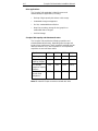
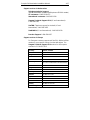
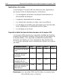
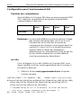
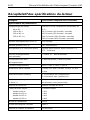
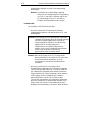
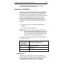
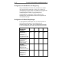
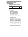
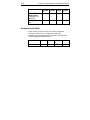
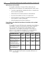
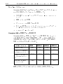
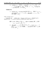
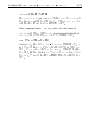
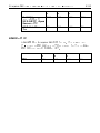
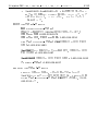
Scorpion 240 capacity and data-transfer rates
The Scorpion 240 provides the following capacities and
sustained data-transfer rates, depending upon the type and
length of tape media used. These capacities and data-transfer
rates are based on a 2:1 data compression. Uncompressed
capacities are one half these values.
Tape format: DDS DDS-2 DDS-3 DDS-4
Tape length (m)
90 120 125 150
Single-cartridge
capacity (Gbytes)
4.0 8.0 24.0 40.0
Six-cartridge
magazine capacity
(Gbytes)
24.0 48.0 144.0 240.0
Sustained Data-
transfer Rate
(Mbyte/sec)
1.83 1.83 5.5 5.5
Note. 60-meter DDS tape cannot be used with this drive.

Scorpion 240 Autoloader Installation Manual A-9
Before you begin
Precautions
Caution.
Observe the following precautions to avoid
electrostatic damage to the internal autoloader.
•
Do not remove the drive from the antistatic bag until you
are ready to install it.
•
Before you remove the drive from the antistatic bag, touch
a grounded metal surface to discharge any static
electricity buildup from your body.
•
Hold the drive only by its edges and avoid direct contact
with any electronic components.
•
If you need to put down the drive, lay it on top of the
antistatic bag or place it inside the bag.
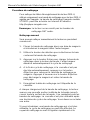
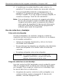
Unpacking and inspection
Although Seagate autoloaders are inspected and carefully
packaged at the factory, damage may occur during shipping.
Follow these steps for unpacking the autoloader.
1. Inspect the shipping container. Notify your shipper
immediately if you find any damage.
2. Place the shipping container on a flat, clean, stable
surface. Then carefully remove the contents and verify
the packing list. If parts are missing or the equipment is
damaged notify your Seagate representative.
3. Save the drive container and packing materials in case
you ever need to ship the drive.

A-10 Scorpion 240 Autoloader Installation Manual
Installing the internal autoloader
This chapter describes how to configure, mount, and attach
cables to the
internal
Scorpion 240 autoloader.
Configuring the internal autoloader
Before you install the internal version of the Scorpion 240 in
your computer, you may need to configure the drive to work
with your system.
Default settings
The default settings for the internal drive are listed below:
•
The drive is set for SCSI ID 6.
•
Parity checking is enabled.
•
SCSI terminator power is disabled.
•
Data compression is enabled.
•
Power-on self-test diagnostics are enabled.
•
MRS checking is enabled
(the drive will not write to non-MRS tapes).
If these default settings are appropriate for your computer
system, then continue to “Mounting the internal autoloader” on
page A-15.
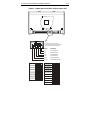
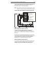
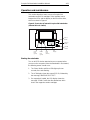
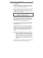
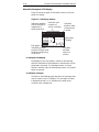
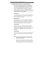
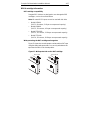
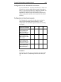
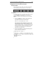
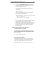
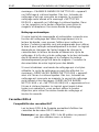
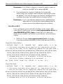
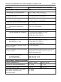
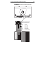
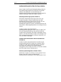
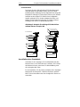
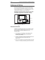
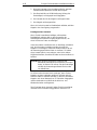
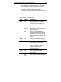
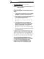
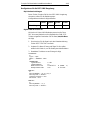
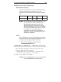
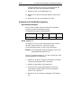
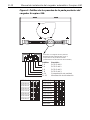
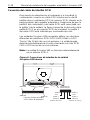
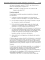
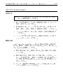
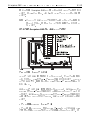
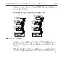
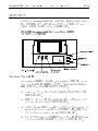
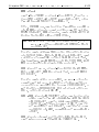
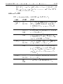
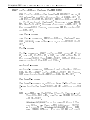
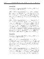
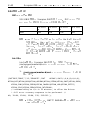
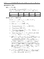
Changing jumper settings
To change the SCSI ID, parity checking, or termination power,
use the jumpers on the back of the drive, as shown in Figure
1 on the following page.
Note.
Power down the drive before changing jumpers or dip
switches. Changes take effect when the drive restarts.

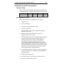
Scorpion 240 Autoloader Installation Manual A-11
Figure 1. Jumper pins on the back of the Scorpion 240
SCSI ID=0
SCSI ID=1
SCSI ID=2
SCSI ID=3
SCSI ID=4
SCSI ID=5
SCSI ID=6
SCSI ID=7
SCSI ID=8
SCSI ID=9
SCSI ID=10
SCSI ID=11
SCSI ID=12
SCSI ID=13
SCSI ID=14
SCSI ID=15
Parity enable
Term. power
Default jumper settings shown
(SCSI ID 6, parity checking enabled,
and termination power disabled)
Pins: Function:
1-2 SCSI ID bit 0
3-4 SCSI ID bit 1
5-6 SCSI ID bit 2
7-8 SCSI ID bit 3
9-10 Parity checking
11-12 Termination Power

A-12 Scorpion 240 Autoloader Installation Manual
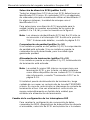
SCSI Address Selection (pins 1 through 8)
Each SCSI device on a SCSI bus must have a unique SCSI
ID. The SCSI controller or host adapter generally uses ID 7.
In some systems, the boot drive uses ID 0 or ID 1.
You can select an appropriate SCSI address used by the
drive by placing the appropriate jumpers on pins pairs 1-2
through 7-8, as shown in Figure 1.
Note: SCSI ID numbers 8 through 15 will only be recognized
if dip switch 9 is “ON.” See page A-14 for details.
Parity checking (pins 9 and 10)
If a jumper is installed on pins 9 and 10, parity checking is
enabled. If no jumper is installed, parity checking is disabled,
but parity is still generated by the drive.
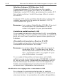
Terminator power (pins 11 and 12)
If a jumper is installed on pins 11 and 12, terminator power is
enabled.
Note: The internal Scorpion 240 does
not
provide SCSI
termination, and therefore should not be installed as
the last device in a SCSI chain. See “SCSI termination”
on page A-16 for more information.
If the terminator power jumper is installed, be careful not to
short the TERMPWR signal to ground. In the event of a short,
terminator power to the bus will be interrupted. After the short
is removed, a fuse in the drive will automatically reset,
restoring terminator power.
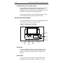
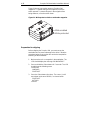
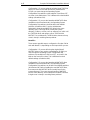
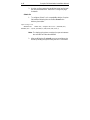
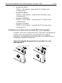
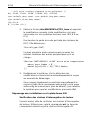
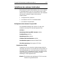
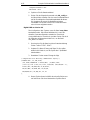
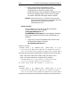
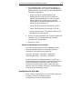
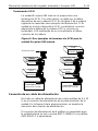
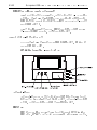
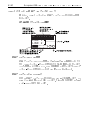
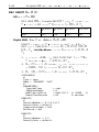
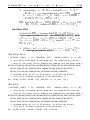
Changing dip-switch settings
To change data compression, MRS checking, power-on self-
test diagnostics, operating system settings, Wide/Narrow
SCSI selection, or the drive’s inquiry string, you must use the
dip switches on the underside of the internal drive.

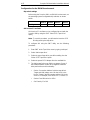
Scorpion 240 Autoloader Installation Manual A-13
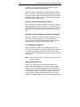
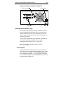
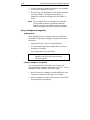
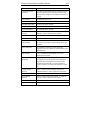
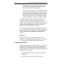
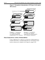
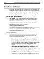
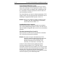
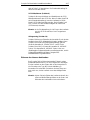
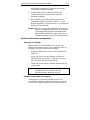
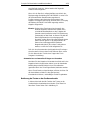
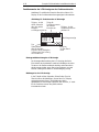
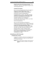
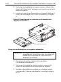
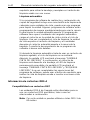
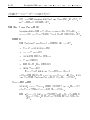
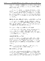
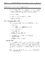
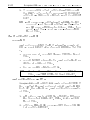
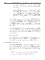
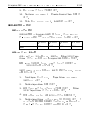
Figure 2 shows the location of dip switches on the
underside
of the internal Scorpion 240. Each of these switches is
described in detail on subsequent pages.
Note. Power down the drive before changing jumpers or dip
switches. Changes take effect when the drive restarts.
Figure 2. Dip-switch settings for internal Scorpion 240
Data compression (DC)
SCSI DC control
Media recognition
Self Test
Wide/Narrow SCSI
Inquiry String support
1
2
3
4
5
6
7
8
9
10
O
N
Default settings shown
Operating-system
configuration
switches
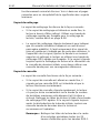
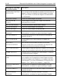
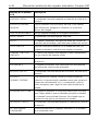
Data compression (switches 1 and 2)
If switch 1 is ON (the default setting), hardware data
compression is enabled when the drive is powered on. If
switch 1 is OFF, hardware data compression is disabled at
power-on.
If dip switch 2 is ON (the default setting) then SCSI commands
can be used to enable or disable hardware data compression. To
prevent hardware data compression from being enabled or
disabled by SCSI commands, set dip switch 2 to OFF.
Media-recognition system (switch 3)
The media-recognition system allows the drive to determine
whether a given tape cartridge conforms to the DDS tape
standard. Use of non-DDS media may appear to give

A-14 Scorpion 240 Autoloader Installation Manual
satisfactory results, but the inferior specifications of such
media can cause data-integrity problems.
Switch 3 enables or disables the media-recognition system
(MRS). If switch 3 is ON (the default setting), the drive reads
and writes to MRS media and reads from but does not write to
non-MRS media. If switch 3 is OFF, the drive reads or writes
both MRS and non-MRS media.
Power-on self-test enable/disable (switch 4)
Switch 4 enables or disables execution of power-on self-test
diagnostics when the drive is powered on. If switch 4 is ON
(the default setting), the drive performs a power-on self test. If
switch 4 is OFF, the drive does not perform a power-on self
test.
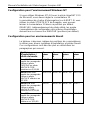
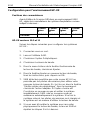
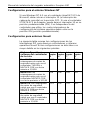
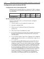
Operating System configuration (switches 5 through 8)
Switches 5 through 8 are used to configure the drive for use
with UNIX, Novell, and Windows NT operating systems.
These procedures are described starting on page A-40. The
default setting for all four of these switches is ON.
SCSI Wide/Narrow (switch 9)
Switch 9 enables or disables SCSI Wide operation on the
SCSI bus. When switch 9 is ON (the default setting), the drive
is capable of operating in Wide (16-bit) SCSI mode. When
switch 9 is OFF, the drive will only operate as a Narrow (8-bit)
SCSI device.
Note: If switch 9 if set to OFF, the drive can only use SCSI ID
values 0 through 7.
Inquiry String (switch 10)
Switch 10 is used to select the Vendor ID that the drive
returns when queried with a SCSI Inquiry command. When
switch 10 is ON (the default setting), the Vendor ID will be
“SEAGATE DAT.” When switch 10 is OFF the Vendor ID will
be “ARCHIVE Python.” The “ARCHIVE Python” Vendor ID
may be used by independent software vendors to provide
software compatibility with previous Seagate DDS tape drives.

Scorpion 240 Autoloader Installation Manual A-15
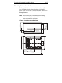
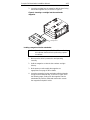
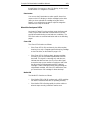
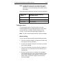
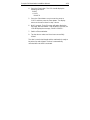
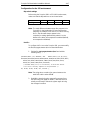
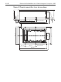
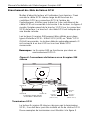
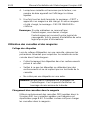
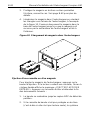
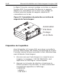
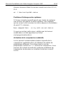
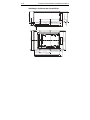
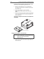
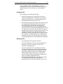
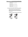
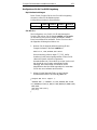
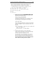
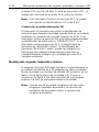
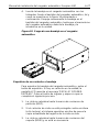
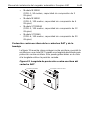
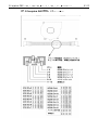
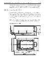
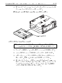
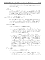
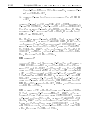
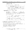
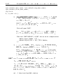
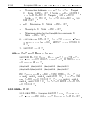
Mounting the internal autoloader
The Scorpion 240 must be mounted horizontally in a 5.25-
inch, full-height drive bay. Mount the drive using four M3.0
metric screws on the sides or bottom of the drive, as shown in
Figure 3. Do not use screws longer than 4 mm or you may
damage the drive.
Note.
When mounting the drive, make sure that nothing
blocks the exhaust fan or the ventilation slots on the
bottom and rear of the autoloader.
Figure 3. Locations of mounting holes
MOUNT HOLE
M3 (4 PLACES)
86
± 0.25
1.8
± 0.25
7.0
± 0.3
45.5
± 0.25
203.2
± 0.25
79.5
± 0.25
11.9
± 0.3
82.6
± 0.6
21.8
± 0.3
45.5
± 0.25
M3 (4 PLACES)
MOUNTING HOLE
149.6
± 0.25
203.2
± 0.5
79.5
± 0.25
139.7
± 0.3
146 +1
.5 –0.5
1.8
± 0.25
224.0 max
224.0 max

A-16 Scorpion 240 Autoloader Installation Manual
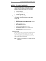
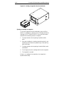
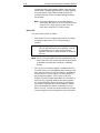
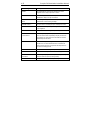
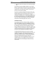
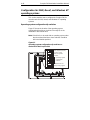
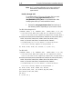
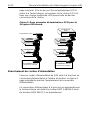
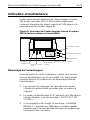
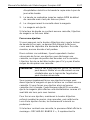
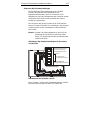
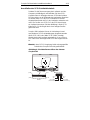
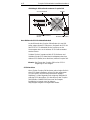
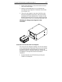
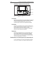
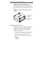
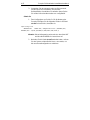
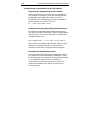
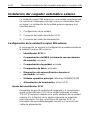
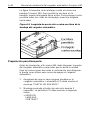
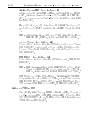
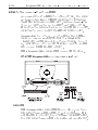
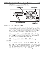
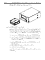
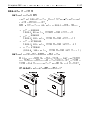
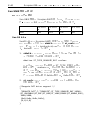
Connecting the SCSI interface cable
Turn off all power to your computer and drive. Then connect a
68-pin wide internal SCSI cable from your SCSI controller to
the SCSI connector on the back of the autoloader. Make sure
that pin 1 on the SCSI controller and cable is connected to pin
1 on the drive. Figure 4 shows the location of SCSI pin 1 on
the drive’s SCSI connector. Pin 1 on the SCSI cable should
be indicated by a colored stripe.
Scorpion 240 drives can be used with two different types of
SCSI interfaces: Ultra2 SCSI (LVD) or “Wide” (16-bit) single-
ended SCSI. The drive can automatically detect whether it is
connected to an LVD or single-ended wide SCSI bus.
Note: The Scorpion 240 will not operate properly in a SCSI-1
environment.
Figure 4. Interface connectors on internal Scorpion 240
Power connector
pin 4
+5V
pin 3: GND
(+5V return)
pin 2: GND
(+12V return)
pin 1
12V
Ultra2 SCSI 68-pin
high-density connector
pin 34
pin 68
pin 35
pin 1
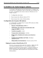
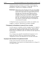
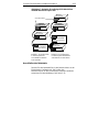
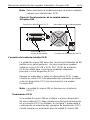
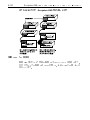
SCSI Termination
The internal Scorpion 240 does
not
provide SCSI termination.
For this reason, it should not be the last device on a SCSI
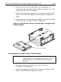
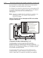
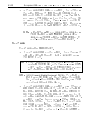
chain. Two termination examples are shown in Figure 5 on
the following page. If the drive is the only SCSI device, attach
the drive to the connector which is next to last on the SCSI

Scorpion 240 Autoloader Installation Manual A-17
chain and attach an LVD/single-ended multi-mode terminator
to the last connector in the chain.
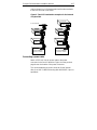
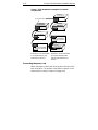
Figure 5. Two SCSI termination examples for the internal
Scorpion 240.
SCSI Controller
(termination enabled)
Internal
Tape drive
SCSI device
(
termination
enabled
)
SCSI device
(
termination
disabled
)
SCSI device
(
termination
disabled
)
(no
termination
)
SCSI Terminator
SCSI Controller
(termination enabled)
Internal
Tape drive
(no
termination
)
Connecting a power cable
Attach a 5/12-volt, four-pin power cable to the power
connector on the back of the drive. Figure 4 on the previous
page shows the location of the power connector.
The recommended 4-pin power connector for the internal
drive is an AMP 1-48024-0 housing with AMP 60617-1 pins or
equivalent.

A-18 Scorpion 240 Autoloader Installation Manual
Installing the external autoloader
The external Scorpion 240 is a compact external drive that
connects to the host computer as a turnkey subsystem.
Installing the external drive involves three simple steps:
1. Configuring the drive
2. Connecting the SCSI interface cable
3. Connecting the power cord
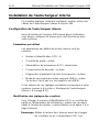
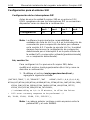
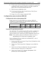
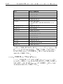
Configuring the external Scorpion 240
The following is the default configuration for the external
Scorpion 240:
•
SCSI ID:
6
•
Media Recognition System (MRS) checking:
enabled.
•
Parity checking:
enabled.
•
Data compression:
enabled.
•
Power-on self-test diagnostics:
enabled.
•
Host operating system:
Windows 95/98/NT/2000
•
Termination power:
supplied to the SCSI bus.
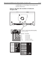
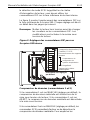
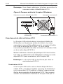
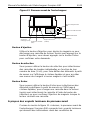
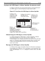
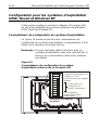
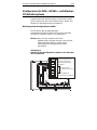
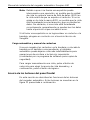
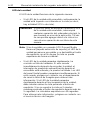
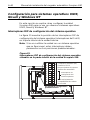
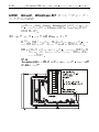
Setting the SCSI ID
Make sure that the drive is turned off; then set the SCSI ID for
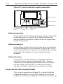
the drive using the push-button switch on the back of the
external drive. Figure 6 on the following page shows this
switch, as well as the two SCSI interface connectors, on/off
switch, and the power-cord connector.
Note:
The drive must be restarted for any change in SCSI ID
to take effect.
A página está carregando...
A página está carregando...
A página está carregando...
A página está carregando...
A página está carregando...
A página está carregando...
A página está carregando...
A página está carregando...
A página está carregando...
A página está carregando...
A página está carregando...
A página está carregando...
A página está carregando...
A página está carregando...
A página está carregando...
A página está carregando...
A página está carregando...
A página está carregando...
A página está carregando...
A página está carregando...
A página está carregando...
A página está carregando...
A página está carregando...
A página está carregando...
A página está carregando...
A página está carregando...
A página está carregando...
A página está carregando...
A página está carregando...
A página está carregando...
A página está carregando...
A página está carregando...
A página está carregando...
A página está carregando...
A página está carregando...
A página está carregando...
A página está carregando...
A página está carregando...
A página está carregando...
A página está carregando...
A página está carregando...
A página está carregando...
A página está carregando...
A página está carregando...
A página está carregando...
A página está carregando...
A página está carregando...
A página está carregando...
A página está carregando...
A página está carregando...
A página está carregando...
A página está carregando...
A página está carregando...
A página está carregando...
A página está carregando...
A página está carregando...
A página está carregando...
A página está carregando...
A página está carregando...
A página está carregando...
A página está carregando...
A página está carregando...
A página está carregando...
A página está carregando...
A página está carregando...
A página está carregando...
A página está carregando...
A página está carregando...
A página está carregando...
A página está carregando...
A página está carregando...
A página está carregando...
A página está carregando...
A página está carregando...
A página está carregando...
A página está carregando...
A página está carregando...
A página está carregando...
A página está carregando...
A página está carregando...
A página está carregando...
A página está carregando...
A página está carregando...
A página está carregando...
A página está carregando...
A página está carregando...
A página está carregando...
A página está carregando...
A página está carregando...
A página está carregando...
A página está carregando...
A página está carregando...
A página está carregando...
A página está carregando...
A página está carregando...
A página está carregando...
A página está carregando...
A página está carregando...
A página está carregando...
A página está carregando...
A página está carregando...
A página está carregando...
A página está carregando...
A página está carregando...
A página está carregando...
A página está carregando...
A página está carregando...
A página está carregando...
A página está carregando...
A página está carregando...
A página está carregando...
A página está carregando...
A página está carregando...
A página está carregando...
A página está carregando...
A página está carregando...
A página está carregando...
A página está carregando...
A página está carregando...
A página está carregando...
A página está carregando...
A página está carregando...
A página está carregando...
A página está carregando...
A página está carregando...
A página está carregando...
A página está carregando...
A página está carregando...
A página está carregando...
A página está carregando...
A página está carregando...
A página está carregando...
A página está carregando...
A página está carregando...
A página está carregando...
A página está carregando...
A página está carregando...
A página está carregando...
A página está carregando...
A página está carregando...
A página está carregando...
A página está carregando...
A página está carregando...
A página está carregando...
A página está carregando...
A página está carregando...
A página está carregando...
A página está carregando...
A página está carregando...
A página está carregando...
A página está carregando...
A página está carregando...
A página está carregando...
A página está carregando...
A página está carregando...
A página está carregando...
A página está carregando...
A página está carregando...
A página está carregando...
A página está carregando...
A página está carregando...
A página está carregando...
A página está carregando...
A página está carregando...
A página está carregando...
A página está carregando...
A página está carregando...
A página está carregando...
A página está carregando...
A página está carregando...
A página está carregando...
A página está carregando...
A página está carregando...
A página está carregando...
A página está carregando...
A página está carregando...
A página está carregando...
A página está carregando...
A página está carregando...
A página está carregando...
A página está carregando...
A página está carregando...
A página está carregando...
A página está carregando...
A página está carregando...
A página está carregando...
A página está carregando...
A página está carregando...
A página está carregando...
A página está carregando...
A página está carregando...
A página está carregando...
A página está carregando...
A página está carregando...
A página está carregando...
A página está carregando...
A página está carregando...
A página está carregando...
A página está carregando...
A página está carregando...
A página está carregando...
A página está carregando...
A página está carregando...
A página está carregando...
A página está carregando...
A página está carregando...
A página está carregando...
A página está carregando...
A página está carregando...
A página está carregando...
A página está carregando...
A página está carregando...
A página está carregando...
A página está carregando...
A página está carregando...
A página está carregando...
A página está carregando...
A página está carregando...
A página está carregando...
A página está carregando...
A página está carregando...
A página está carregando...
A página está carregando...
A página está carregando...
A página está carregando...
A página está carregando...
A página está carregando...
A página está carregando...
A página está carregando...
A página está carregando...
A página está carregando...
A página está carregando...
A página está carregando...
A página está carregando...
A página está carregando...
A página está carregando...
A página está carregando...
A página está carregando...
A página está carregando...
A página está carregando...
A página está carregando...
A página está carregando...
A página está carregando...
A página está carregando...
A página está carregando...
A página está carregando...
A página está carregando...
A página está carregando...
A página está carregando...
A página está carregando...
A página está carregando...
A página está carregando...
A página está carregando...
A página está carregando...
A página está carregando...
A página está carregando...
A página está carregando...
A página está carregando...
A página está carregando...
A página está carregando...
A página está carregando...
A página está carregando...
A página está carregando...
A página está carregando...
A página está carregando...
A página está carregando...
A página está carregando...
A página está carregando...
A página está carregando...
A página está carregando...
A página está carregando...
A página está carregando...
A página está carregando...
A página está carregando...
A página está carregando...
A página está carregando...
A página está carregando...
A página está carregando...
A página está carregando...
A página está carregando...
A página está carregando...
A página está carregando...
A página está carregando...
A página está carregando...
A página está carregando...
A página está carregando...
A página está carregando...
A página está carregando...
A página está carregando...
A página está carregando...
A página está carregando...
A página está carregando...
A página está carregando...
A página está carregando...
A página está carregando...
A página está carregando...
A página está carregando...
A página está carregando...
A página está carregando...
A página está carregando...
A página está carregando...
-
 1
1
-
 2
2
-
 3
3
-
 4
4
-
 5
5
-
 6
6
-
 7
7
-
 8
8
-
 9
9
-
 10
10
-
 11
11
-
 12
12
-
 13
13
-
 14
14
-
 15
15
-
 16
16
-
 17
17
-
 18
18
-
 19
19
-
 20
20
-
 21
21
-
 22
22
-
 23
23
-
 24
24
-
 25
25
-
 26
26
-
 27
27
-
 28
28
-
 29
29
-
 30
30
-
 31
31
-
 32
32
-
 33
33
-
 34
34
-
 35
35
-
 36
36
-
 37
37
-
 38
38
-
 39
39
-
 40
40
-
 41
41
-
 42
42
-
 43
43
-
 44
44
-
 45
45
-
 46
46
-
 47
47
-
 48
48
-
 49
49
-
 50
50
-
 51
51
-
 52
52
-
 53
53
-
 54
54
-
 55
55
-
 56
56
-
 57
57
-
 58
58
-
 59
59
-
 60
60
-
 61
61
-
 62
62
-
 63
63
-
 64
64
-
 65
65
-
 66
66
-
 67
67
-
 68
68
-
 69
69
-
 70
70
-
 71
71
-
 72
72
-
 73
73
-
 74
74
-
 75
75
-
 76
76
-
 77
77
-
 78
78
-
 79
79
-
 80
80
-
 81
81
-
 82
82
-
 83
83
-
 84
84
-
 85
85
-
 86
86
-
 87
87
-
 88
88
-
 89
89
-
 90
90
-
 91
91
-
 92
92
-
 93
93
-
 94
94
-
 95
95
-
 96
96
-
 97
97
-
 98
98
-
 99
99
-
 100
100
-
 101
101
-
 102
102
-
 103
103
-
 104
104
-
 105
105
-
 106
106
-
 107
107
-
 108
108
-
 109
109
-
 110
110
-
 111
111
-
 112
112
-
 113
113
-
 114
114
-
 115
115
-
 116
116
-
 117
117
-
 118
118
-
 119
119
-
 120
120
-
 121
121
-
 122
122
-
 123
123
-
 124
124
-
 125
125
-
 126
126
-
 127
127
-
 128
128
-
 129
129
-
 130
130
-
 131
131
-
 132
132
-
 133
133
-
 134
134
-
 135
135
-
 136
136
-
 137
137
-
 138
138
-
 139
139
-
 140
140
-
 141
141
-
 142
142
-
 143
143
-
 144
144
-
 145
145
-
 146
146
-
 147
147
-
 148
148
-
 149
149
-
 150
150
-
 151
151
-
 152
152
-
 153
153
-
 154
154
-
 155
155
-
 156
156
-
 157
157
-
 158
158
-
 159
159
-
 160
160
-
 161
161
-
 162
162
-
 163
163
-
 164
164
-
 165
165
-
 166
166
-
 167
167
-
 168
168
-
 169
169
-
 170
170
-
 171
171
-
 172
172
-
 173
173
-
 174
174
-
 175
175
-
 176
176
-
 177
177
-
 178
178
-
 179
179
-
 180
180
-
 181
181
-
 182
182
-
 183
183
-
 184
184
-
 185
185
-
 186
186
-
 187
187
-
 188
188
-
 189
189
-
 190
190
-
 191
191
-
 192
192
-
 193
193
-
 194
194
-
 195
195
-
 196
196
-
 197
197
-
 198
198
-
 199
199
-
 200
200
-
 201
201
-
 202
202
-
 203
203
-
 204
204
-
 205
205
-
 206
206
-
 207
207
-
 208
208
-
 209
209
-
 210
210
-
 211
211
-
 212
212
-
 213
213
-
 214
214
-
 215
215
-
 216
216
-
 217
217
-
 218
218
-
 219
219
-
 220
220
-
 221
221
-
 222
222
-
 223
223
-
 224
224
-
 225
225
-
 226
226
-
 227
227
-
 228
228
-
 229
229
-
 230
230
-
 231
231
-
 232
232
-
 233
233
-
 234
234
-
 235
235
-
 236
236
-
 237
237
-
 238
238
-
 239
239
-
 240
240
-
 241
241
-
 242
242
-
 243
243
-
 244
244
-
 245
245
-
 246
246
-
 247
247
-
 248
248
-
 249
249
-
 250
250
-
 251
251
-
 252
252
-
 253
253
-
 254
254
-
 255
255
-
 256
256
-
 257
257
-
 258
258
-
 259
259
-
 260
260
-
 261
261
-
 262
262
-
 263
263
-
 264
264
-
 265
265
-
 266
266
-
 267
267
-
 268
268
-
 269
269
-
 270
270
-
 271
271
-
 272
272
-
 273
273
-
 274
274
-
 275
275
-
 276
276
-
 277
277
-
 278
278
-
 279
279
-
 280
280
-
 281
281
-
 282
282
-
 283
283
-
 284
284
-
 285
285
-
 286
286
-
 287
287
-
 288
288
-
 289
289
-
 290
290
-
 291
291
-
 292
292
-
 293
293
-
 294
294
-
 295
295
-
 296
296
-
 297
297
-
 298
298
-
 299
299
-
 300
300
-
 301
301
-
 302
302
-
 303
303
-
 304
304
-
 305
305
-
 306
306
-
 307
307
-
 308
308
-
 309
309
-
 310
310
-
 311
311
-
 312
312
-
 313
313
-
 314
314
-
 315
315
-
 316
316
-
 317
317
-
 318
318
-
 319
319
-
 320
320
-
 321
321


