Yamaha NS-P430 Manual do proprietário

Categoria
Alto-falantes portáteis
Tipo
Manual do proprietário

Este manual também é adequado para

NS-P430/
NS-P436
(NS-P430/NS-P436: NX-430P + NX-C430 + YST-SW015)
HOME CINEMA 5.1CH SPEAKER PACKAGE/
HOME CINEMA 6.1CH SPEAKER PACKAGE
OWNER’S MANUAL
U B
NS-P430-436(UB)-PREc 03.2.28, 7:02 PM1
II
Explanation of Graphical Symbols
The lightning flash with arrowhead
symbol, within an equilateral triangle,
is intended to alert you to the
presence of uninsulated “dangerous
voltage” within the product’s
enclosure that may be of sufficient
magnitude to constitute a risk of
electric shock to persons.
The exclamation point within an
equilateral triangle is intended to alert
you to the presence of important
operating and maintenance
(servicing) instructions in the
literature accompanying the
appliance.
IMPORTANT SAFETY INSTRUCTIONS
1 Read these instructions.
2 Keep these instructions.
3 Heed all warnings.
4 Follow all instructions.
5 Do not use this apparatus near water.
6 Clean only with dry cloth.
7 Do not block any ventilation openings. Install in
accordance with the manufacturer’s instructions.
8 Do not install near any heat sources such as radiators,
heat registers, stoves, or other apparatus (including
amplifiers) that produce heat.
9 Do not defeat the safety purpose of the polarized or
grounding-type plug. A polarized plug has two blades
with one wider than the other. A grounding type plug
has two blades and a third grounding prong. The wide
blade or the third prong are provided for your safety. If
the provided plug does not fit into your outlet, consult
an electrician for replacement of the obsolete outlet.
10 Protect the power cord from being walked on or
pinched particularly at plugs, convenience receptacles,
and the point where they exit from the apparatus.
11 Only use attachments/accessories specified by the
manufacturer.
12 Use only with the cart, stand, tripod,
bracket, or table specified by the
manufacturer, or sold with the
apparatus. When a cart is used, use
caution when moving the cart/
apparatus combination to avoid injury
from tip-over.
13 Unplug this apparatus during lightning storms or when
unused for long periods of time.
14 Refer all servicing to qualified service personnel.
Servicing is required when the apparatus has been
damaged in any way, such as power-supply cord or
plug is damaged, liquid has been spilled or objects
have fallen into the apparatus, the apparatus has been
exposed to rain or moisture, does not operate normally,
or has been dropped.
Be sure to allow spaces of at least 20 cm above,
behind and on both sides of the unit.
Do not place the following objects on this unit:
A vessel with water in it.
If the vessel falls by vibrations and water spills, it
may cause damage to the unit, and/or you may get
an electric shock.
WARNING
TO REDUCE THE RISK OF FIRE OR ELECTRIC
SHOCK, DO NOT EXPOSE THIS APPLIANCE TO RAIN
OR MOISTURE.
CAUTION: TO REDUCE THE RISK OF
ELECTRIC SHOCK, DO NOT REMOVE
COVER (OR BACK). NO USER-SERVICEABLE
PARTS INSIDE. REFER SERVICING TO
QUALIFIED SERVICE PERSONNEL.
RISK OF ELECTRIC SHOCK
DO NOT OPEN
CAUTION
IMPORTANT
Please record the serial number of this system in
the space below.
Model:
Serial No.:
The serial number is located on the rear of the
main unit.
Retain this Owners Manual in a safe place for
future reference.
NS-P430-436(UB)-PREc 03.2.28, 7:02 PM2
III
We Want You Listening For A Lifetime
YAMAHA and the Electronic Industries Associations
Consumer Electronics Group want you to get the most out
of your equipment by playing it at a safe level. One that lets
the sound come through loud and clear without annoying
blaring or distortion and, most importantly, without
affecting your sensitive hearing.
Since hearing damage from loud sounds is
often undetectable until it is too late, YAMAHA
and the Electronic Industries Associations
Consumer Electronics Group recommend you
to avoid prolonged exposure from excessive
volume levels.
FCC INFORMATION (for US customers only)
1. IMPORTANT NOTICE : DO NOT MODIFY THIS
UNIT!
This product, when installed as indicated in the
instructions contained in this manual, meets FCC
requirements. Modifications not expressly approved
by Yamaha may void your authority, granted by the
FCC, to use the product.
2. IMPORTANT : When connecting this product to
accessories and/or another product use only high
quality shielded cables. Cable/s supplied with this
product MUST be used. Follow all installation
instructions. Failure to follow instructions could void
your FCC authorization to use this product in the
USA.
3. NOTE : This product has been tested and found to
comply with the requirements listed in FCC
Regulations, Part 15 for Class B digital devices.
Compliance with these requirements provides a
reasonable level of assurance that your use of this
product in a residential environment will not result in
harmful interference with other electronic devices.
This equipment generates/uses radio frequencies
and, if not installed and used according to the
instructions found in the users manual, may cause
interference harmful to the operation of other
electronic devices.
Compliance with FCC regulations does not guarantee that
interference will not occur in all installations. If this
product is found to be the source of interference, which
can be determined by turning the unit OFF and ON,
please try to eliminate the problem by using one of the
following measures:
Relocate either this product or the device that is being
affected by the interference.
Utilize power outlets that are on different branch (circuit
breaker or fuse) circuits or install AC line filter/s.
In the case of radio or TV interference, relocate/reorient
the antenna. If the antenna lead-in is 300 ohm ribbon
lead, change the lead-in to coaxial type cable.
If these corrective measures do not produce satisfactory
results, please contact the local retailer authorized to
distribute this type of product. If you can not locate the
appropriate retailer, please contact Yamaha Electronics
Corp., U.S.A. 6660 Orangethorpe Ave, Buena Park, CA
90620.
The above statements apply ONLY to those products
distributed by Yamaha Corporation of America or its
subsidiaries.
NS-P430-436(UB)-PREc 03.2.28, 7:02 PM3
IV
Speaker cables
Subwoofer cable
Fasteners (for NX-C430)
Nonskid pads (for YST-SW015)
Main and rear speakers
(and rear center speaker for NS-P436)
Center speaker
Subwoofer
UNPACKING Please check to make sure all listed items are included.
[4m]
[15m]
X 2
X 3
NX-430P
NX-C430
YST-SW015
X 2
<NS-P430>
X 3
<
NS-P436>
X 4
<NS-P430>
X 5
<NS-P436>
SUBWOOFER SYSTEM YST-SW015
STANDBY/ON B.A.S.S. HIGH CUT
50
150Hz
VOLUME
0
10
SPECIAL INSTRUCTIONS FOR U.K. MODEL
IMPORTANT:
THE WIRES IN MAINS LEAD ARE COLOURED IN
ACCORDANCE WITH THE FOLLOWING CODE:
Blue: NEUTRAL
Brown: LIVE
As the colours of the wires in the mains lead of this
apparatus may not correspond with the coloured markings
identifying the terminals in your plug, proceed as follows:
The wire which is coloured BLUE must be connected to
the terminal which is marked with the letter N or coloured
BLACK. The wire which is coloured BROWN must be
connected to the terminal which is marked with the letter L
or coloured RED. Making sure that neither core is
connected to the earth terminal of the three pin plug.
For U.K. customers
If the socket outlets in the home are not suitable for the plug
supplied with this appliance, it should be cut off and an
appropriate 3 pin plug fitted. For details, refer to the
instructions described below.
Note: The plug severed from the mains lead must be
destroyed, as a plug with bared flexible cord is hazardous if
engaged in a live socket outlet.
For Canadian Customers
To prevent electric shock, match wide blade of plug to
wide slot and fully insert.
This Class B digital apparatus complies with Canadian
ICES-003.
NS-P430-436(UB)-PREc 03.2.28, 7:02 PM4
English
E-1
To assure the finest performance, please read this manual
carefully. Keep it in a safe place for future reference.
Install the speakers in a cool, dry, clean place away from
windows, heat sources, sources of excessive vibration, dust,
moisture and cold. Avoid sources of humming (transformers,
motors). To prevent fire or electric shock, do not expose the
speakers to rain or water.
To prevent the enclosure from warping or discoloring, do not
place the speakers where they will be exposed to direct sunlight
or excessive humidity.
Avoid installing the speakers where foreign objects may fall onto
them and/or where they may be exposed to liquid dripping or
splashing.
Do not place the following objects on top of the speakers:
Other components, as they might cause damage and/or
discoloration on the surface of the speakers.
Burning objects (i.e. candles), as they might cause fire,
damage to the speakers and/or personal injury.
Containers with liquid in them, as they might cause electric
shock to the user and/or damage to the speakers.
Do not place the speakers where they are liable to be knocked
over or struck by falling objects. Stable placement will also
ensure better sound performance.
Placing the speakers on the same shelf or rack as the turntable
can result in feedback.
Secure placement or installation is the owners responsibility.
YAMAHA shall not be liable for any accident caused by improper
placement or installation of speakers.
Any time you note distortion, reduce the volume control on your
amplifier to a lower setting. Never allow your amplifier to be
driven into clipping. Otherwise the speakers may be damaged.
When using an amplifier with a rated output power higher than
the nominal input power of the speakers, care should be taken
never to exceed the speakers maximum input.
Do not attempt to clean the speakers with chemical solvents as
this might damage the finish. Use a clean, dry cloth.
Do not attempt to modify or fix the speakers. Contact qualified
YAMAHA service personnel when any service is needed. The
cabinet should never be opened for any reason.
Be sure to read the TROUBLESHOOTING section regarding
common operating errors before concluding that the speakers
are faulty.
For YST-SW015
Do not operate this unit upside down. It may overheat, possibly
causing damage.
Do not use excessive force on switches, controls or connection
wires. When moving this unit, first disconnect the power plug
and the wires connected to other equipments. Never pull the
wires themselves.
Since this unit has a built-in power amplifier, heat will radiate
from the rear panel. Place the unit apart from the walls, allowing
spaces of at least 20 cm above, behind and on both sides of the
unit to prevent fire or damage. Furthermore, do not position with
the rear panel facing down on the floor or other surfaces.
When using a humidifier, be sure to avoid condensation inside
this unit by allowing enough spaces around this unit or avoiding
excess humidification. Condensation might cause a fire, damage
to this unit, and/or electric shock.
CAUTION: Read this before operating your unit.
Thank you for selecting this YAMAHA NS-P430/NS-P436 Speaker Package.
Do not cover the rear panel of this unit with a newspaper, a
tablecloth, a curtain, etc. in order not to obstruct heat radiation. If
the temperature inside this unit rises, it may cause fire, damage
to this unit and/or personal injury.
Do not plug in this unit to a wall outlet until all connections are
completed.
The voltage to be used must be the same as that specified on
the rear panel. Using this unit with a higher voltage than
specified is dangerous and may cause fire, damage to this unit,
and/or personal injury. YAMAHA will not be held responsible for
any damage resulting from use of this unit with a voltage other
than specified.
To prevent lightning damage, disconnect the AC power plug
when there is an electric storm.
Super-bass frequencies reproduced by this unit may cause a
turntable to generate a howling sound. In such a case, move this
unit away from the turntable.
This unit may be damaged if certain sounds are continuously
outputted at high volume level. For example, if 20 Hz50 Hz sine
waves from a test disc, bass sounds from electronic instruments,
etc. are continuously outputted, or when the stylus of a turntable
touches the surface of a disc, reduce the volume level to prevent
this unit from being damaged.
If you hear distorted noise (i.e. unnatural, intermittent rapping or
hammering sounds) coming from this unit, reduce the volume
level. Extremely loud playing of a movie soundtracks low
frequency, bass-heavy sounds or similarly loud popular music
passages can damage this speaker system.
Vibration generated by super-bass frequencies may distort
images on a TV. In such a case, move this unit away from the TV
set.
When disconnecting the power cord from the wall outlet, grasp
the plug; do not pull the cord.
When not planning to use this unit for a long period (i.e. vacation,
etc.), disconnect the AC power plug from the wall outlet.
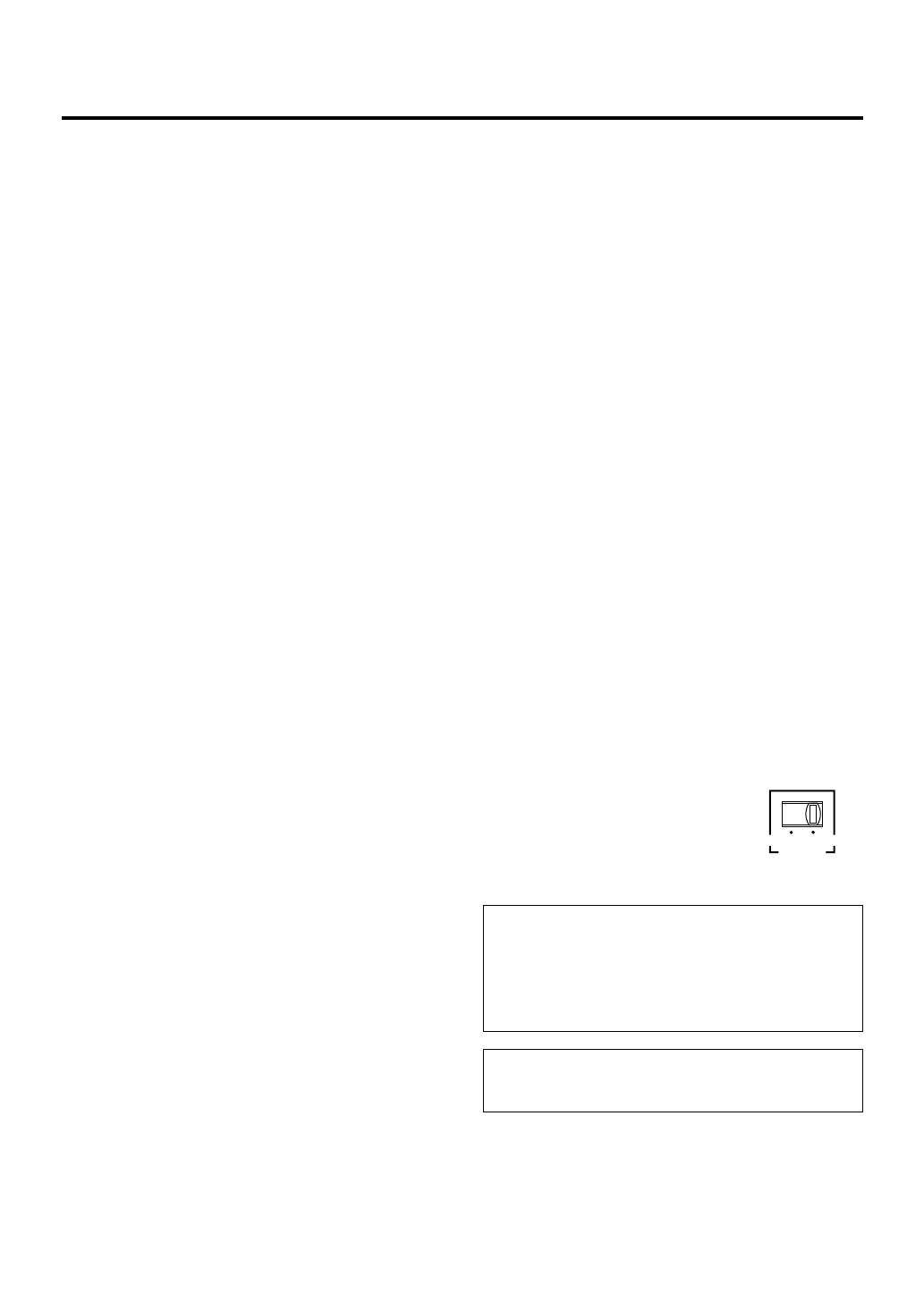
VOLTAGE SELECTOR
(For China, Korean and General models)
The voltage selector switch on the rear
panel of this unit must be set for your
local main voltage BEFORE plugging
this unit into the AC main supply.
Voltages are 110-120/220-240 V AC, 50/
60 Hz.
Standby mode
If the POWER switch is set to the ON position and the AUTO
STANDBY switch is set to the HIGH or LOW position, this unit
turns into the standby mode when no signal is received by this
unit for 7 to 8 minutes.
In this state, this unit is designed to consume a very small
quantity of power.
WARNING
TO REDUCE THE RISK OF FIRE OR ELECTRIC SHOCK, DO
NOT EXPOSE THIS UNIT TO RAIN OR MOISTURE.
110V
120V 220V
240V
VOLTAGE
SELECTOR
NS-P430-436 (UB) 03.2.28, 7:02 PM1
E-2
CONTENTS
IMPORTANT SAFETY INSTRUCTIONS ........ II
UNPACKING .................................................. IV
CAUTION ......................................................... 1
COMPONENTS OF THE PACKAGE .............. 2
SETTING UP THE SPEAKERS ...................... 3
Placing the subwoofer ................................... 4
Placing the center speaker ............................. 4
Mounting the main/rear/center speakers
(and rear center speaker for NS-P436)
on a wall ............................................................
5
Mounting the main/rear speakers
(and rear center speaker for NS-P436)
by using commercially available speaker
stands or brackets .............................................
6
CONNECTIONS.............................................. 7
An example of basic connections .................... 7
How to connect speaker cables to the input
and output terminals of the speakers ............... 9
USING THE SUBWOOFER (YST-SW015) ... 10
Controls and their functions .......................... 10
Automatic power-switching functon ................. 11
Adjusting the subwoofer before use ................ 12
Frequency characteristics ................................ 13
ADVANCED YAMAHA ACTIVE SERVO
TECHNOLOGY (for YST-SW015) ................ 14
TROUBLESHOOTING .................................. 15
SPECIFICATIONS .......................... Back Cover
COMPONENTS OF THE PACKAGE
<NX-430P>
2-way acoustic-suspension speaker system used for
the main and rear speakers (and rear center speaker for
NS-P436)
<NX-C430>
2-way acoustic-suspension speaker system used for
the center speaker
<YST-SW015>
Active Servo Processing Subwoofer System with a
built-in power amplifier
This subwoofer system employs Advanced Yamaha
Active Servo Technology which YAMAHA has developed
for reproducing higher quality super-bass sound. (Refer to
page 14 for details on Advanced Yamaha Active Servo
Technology.) This super-bass sound adds a more
realistic, theater-in-the-home effect to your stereo system.
The HIGH CUT control enables you to adjust the tone
balance between the subwoofer and the main speakers.
The Automatic power-switching function saves you the
trouble of pressing the STANDBY/ON button to turn the
power on or turn it to the STANDBY mode.
The speaker package NS-P430 and NS-P436 is designed
for use in a multi-channel audio system such as a home
theater system.
NS-P430 includes four NX-430P speaker systems, one NX-
C430 speaker system and one YST-SW015 subwoofer
system.
NS-P436 includes five NX-430P speaker systems, one NX-
C430 speaker system and one YST-SW015 subwoofer
system.
QD-Bass Technology
QD-Bass (Quatre Dispersion Bass) technology uses
square, pyramid-shaped reflective plates to radiate the
sound in four horizontal directions.
About this manual
This manual is printed prior to production. Design
and specifications are subject to change in part for the
reason of the improvement in operativity ability, and
others. In this case, the product has priority.
Some of the illustrations and names of the package
contents etc. written in this manual may differ from
the actual products and the names written on the
package etc.
NS-P430-436 (UB) 03.2.28, 7:02 PM2
English
E-3
SETTING UP THE SPEAKERS
Before making connections, place all speakers in their respective positions. The positioning of the speakers is important
because it controls the whole sound quality of this system.
Place the speakers depending on your listening position by following the instructions below.
Speaker configuration
<NS-P430>
This speaker package employs a 6 speaker configuration: 2
main speakers, 2 rear speakers, a center speaker and a
subwoofer.
The main speakers emit main source sound. The rear
speakers emit surround sounds, and the center speaker
emits center sounds (dialog etc.). The subwoofer emits
reinforcing low frequencies on your audio system.
<NS-P436>
This speaker package employs a 7 speaker configuration: 2
main speakers, 2 rear speakers, a center speaker, a rear
center speaker and a subwoofer.
The main speakers emit main source sound. The rear and
rear center speakers emit surround sounds, and the center
speaker emits center sounds (dialog etc.). The subwoofer
emits reinforcing low frequencies on your audio system.
Note
In this speaker package, the same speakers (NX-430P)
are used for the main and rear speakers (and rear
center speaker for NS-P436).
Placing speakers
Main speakers: On both sides of and at approximately
the same height as the TV set.
Rear speakers: Behind your listening position, facing
slightly inward. About 1.8 m (approx. 6
feet) from the floor.
Center speaker: Precisely between the main speakers.
Rear center speaker (for NS-P436):
Precisely between the rear speakers.
Subwoofer: The position of the subwoofer is not so
critical because low bass tones are not
highly directional.
Refer to Placing the subwoofer on
page 4 for a recommended positioning
of the subwoofer.
Main L Center Main R
Rear L
Subwoofer
Rear R
Main L
Main R
Subwoofer
Center
Rear L
Rear R
TV-set
Rear center
(for NS-P436)
Rear center
(for NS-P436)
These speakers feature a magnetically shielded design,
but there is still a chance that placing them too close to a
TV set might impair picture color. Should this happen,
move the speakers away from the TV set.
NS-P430-436 (UB) 03.2.28, 7:02 PM3
E-4
Placing the subwoofer
It is recommended to place the subwoofer on the outside of
either the right or the left main speaker. (See fig. Å .) The
placement shown in fig. ı is also possible, however, if the
subwoofer system is placed directly facing the wall, the
bass effect may die because the sound from it and the
sound reflected by the wall may cancel out each other. To
prevent this from happening, face the subwoofer system at
an angle as shown in fig. Å.
Note
There may be a case that you cannot obtain enough super-
bass sounds from the subwoofer when listening in the
center of the room. This is because standing waves have
been developed between two parallel walls and they cancel
the bass sounds.
In such a case, face the subwoofer obliquely to the wall. It
also may be necessary to break up the parallel surfaces by
placing bookshelves etc. along the walls.
Use the nonskid pads
Put the provided nonskid pads at the four corners on the
bottom of the subwoofer to prevent the subwoofer from
moving by vibrations etc.
( : Subwoofer, : Main speaker)
ıÅ
You can place the speaker on top of the TV if the top is flat,
on the floor under the TV, or inside the TV rack . Be sure to
place the speaker in a stable position.
When placing the speaker on top of the TV, to prevent the
speaker from falling, attach the provided fasteners at two
points on the bottom of the speaker and on the top of the
TV.
Placing the center speaker
Notes
Do not place the speaker on top of a TV whose area is
smaller than the bottom of the speaker. If placed, the
speaker may fall and cause injury.
Do not place the speaker on top of a TV if the top is
inclined.
Do not touch the adhesive surface after peeling off
the seal as this will weaken its adhesive strength.
Thoroughly wipe clean the surface where the fastener
is to be applied. Note that adhesive strength is
weakened if the surface is dirty, oily or wet and that
this may cause the center speaker to fall.
Peel off
the seal
Fastener
NS-P430-436 (UB) 03.2.28, 7:02 PM4
English
E-5
Mounting the main/rear/center speakers (and rear center
speaker for NS-P436) on the wall
You can mount the main, rear and/or center speakers (and/
or rear center speaker for NS-P436) on a wall.
To mount the speakers on a wall, use the holes of the
brackets attached on the speakers back panels.
1 Fasten two screws into a firm wall or wall support at the
interval shown below.
Main/rear/rear center (for NS-P436) .......... 26 mm (1)
Center ............................................. 222.8 mm (8-3/4)
2 Hang the speaker by mounting the holes on the
protruding screws.
* Make sure that the screws are securely affixed by the
narrow parts of the holes.
WARNING
Each speaker weighs as follows.
Main/rear/rear center (for NS-P436)
...................................................... 1.2 kg (2 lbs. 10 oz.)
Center .......................................... 1.7 kg (3 lbs. 12 oz.)
Do not mount them on thin plywood or a wall
composed of a soft surface material. If mounted, the
screws may pull out of the flimsy surface and the
speakers may fall. This may damage the speakers or
cause personal injury.
Do not affix the speakers to a wall using nails,
adhesives, or any other unstable hardware. Long-
term use and vibrations may cause the speakers to
fall.
To avoid accidents resulting from tripping over loose
speaker cables, fix the cables to the wall.
Select an appropriate position on the wall to mount
the speaker so that no one will injure his/her head or
face.
1
26 mm
Holes
2
Wall/ wall support
Tapping screw
(Available at the
hardware store)
Min.
20 mm
Diam. 3.5 to 4 mm
4 mm
Main/rear/rear center (for NS-P436)
Center
222.8 mm
Main/rear/rear center (for NS-P436)
Center
NS-P430-436 (UB) 03.2.28, 7:02 PM5
E-6
The front cover is fastened to the enclosure at four points
and can be removed if desired. To remove the cover, hold
on to both sides and slowly pull straight away from the
speaker. To reattach, line up the four holes on the inner
surface of the cover with the four corresponding pegs on the
speaker and push gently.
Note
When the cover is removed, be sure not to touch the
speaker units with your hands or to exert excessive
force with tools.
Removing the front cover
Main/rear/rear center (for NS-P436)
Center
Mounting the main/rear speakers (and rear center speaker for
NS-P436) by using commercially available speaker stands or
brackets
Using the Yamaha Speaker Stand SPS-10MM (option)
By using the Yamaha Speaker Stand
SPS-10MM, speakers can be placed
on the floor. (Two stands make a set.)
* The SPS-10MM is not available in some areas.
60 mm
You can also use the screw holes on the bottom of the
speaker for installing the speakers on commericially
available speaker stands (if you do not use the
attached mounting brackets.)
A screw with a diameter of 4 mm
can be used.
(Hole depth : 10 mm)
SPS-10MM
NS-P430-436 (UB) 03.2.28, 7:02 PM6
English
E-7
SPEAKERS
MAIN
OUTPUT
SUB
WOOFER
CENTER
REAR CENTER
L
R
L
R
L
R
A
+
+
+
+
+
B
REAR
(SURROUND)
INPUT
/MONO
OFF LOW HIGH
AUTO
STANDBY
NORM REV
PHASE
POWER
ON
OFF
110V
120V 220V
240V
VOLTAGE
SELECTOR
INPUT
/MONO
OFF LOW HIGH
AUTO
STANDBY
NORM REV
PHASE
CENTER CENTER
FRONT R
FRONT R
FRONT LFRONT L
REAR C
REAR C
REAR R
REAR L
REAR L
REAR R
CONNECTIONS
Caution: Plug in the subwoofer and other audio/video components after all connections are
completed.
An example of basic connections
Subwoofer
Amplifier
To AC outlet
Center speaker
Rear speaker
Right
LeftRight
Main speakers
Rear center speaker
(for NS-P436)
Rear speaker
Left
NS-P430-436 (UB) 03.2.28, 7:02 PM7
E-8
Connect the main, center and rear speakers (and rear
center speaker for NS-P436) to the speaker output
terminals of your amplifier with the provided speaker
cables.
* The provided speaker cables have labels marked
FRONT L, FRONT R, CENTER, REAR L, REAR R
(and REAR C for NS-P436). Connect each speaker
cable to the corresponding speaker by following the
figure on page 7.
(The speaker cables marked FRONT L/R are used for
connecting the main speakers to the MAIN speakers
terminals on the amplifier.)
* Connect each speaker making sure not to reverse the
polarity (+, ). If the speaker is connected with
reversed polarity, the sound will be unnatural and lack
bass.
* For the main and rear speakers only, connect one
speaker to the left (marked L) terminals of your
amplifier, and another speaker to the right (marked R)
terminals.
Connect the subwoofer to the line output (pin jack)
terminal(s) of the amplifier.
* To connect with a YAMAHA DSP amplifier (or AV
receiver), connect the SUBWOOFER (or LOW PASS
etc.) terminal on the rear of the DSP amplifier (or AV
receiver) to the L/MONO INPUT terminal of the
subwoofer.
* To connect the subwoofer to the SPLIT SUBWOOFER
terminals on the rear of the DSP amplifier, connect
them to both the left L/MONO and right R INPUT
terminals of the subwoofer.
Note
When connecting to a monaural line output terminal of the
amplifier, connect to the L/MONO INPUT terminal.
NS-P430-436 (UB) 03.2.28, 7:02 PM8
English
E-9
Main speakers
Center speaker
Use the provided speaker cables (4 m). One side of the
speaker cable is red and the other side is black.
Connect the (+) terminals on both the speaker and the
amplifier using the red side of the cable. Connect the ()
terminals on both components using the black side.
Red: positive (+)
Black: negative ()
Rear speakers
Rear center speaker (for NS-P436)
Use the provided speaker cables (15 m). One side of the
speaker cable has a gray line and the other side has no line.
Connect the (+) terminals on both the speaker and the
amplifier using the side with a gray line. Connect the ()
terminals on both components using the side with no line.
Red: positive (+)
Black: negative ()
How to connect speaker cables to the input terminals of the
speakers
For connections, keep the speaker cables as short as possible. Do not bundle or roll up the excess part of the cables. If the
connections are faulty, no sound will be heard from the speakers.
Before connecting
Remove the insulation coating at the extremity of each
speaker cable by twisting the coating off.
How to Connect:
1 Press and hold the terminals tab, as shown in the
figure.
2 Insert the bare wire.
3 Release your finger from the tab to allow it to lock
securely on the cables wire end.
4 Test the firmness of the connection by pulling lightly on
the cable at the terminal.
Note
Do not let the bare speaker wires touch each other as
this could damage the speaker or the amplifier, or both
of them.
Gray line
Red
Black
NS-P430-436 (UB) 03.2.28, 7:03 PM9
E-10
USING THE SUBWOOFER (YST-SW015)
Controls and their functions
1 Power indicator
Lights up in green while the subwoofer is on.
Lights up in red while the subwoofer is set in the
standby mode by the operation of the automatic power-
switching function.
Goes off when the subwoofer is set in the standby
mode.
2 STANDBY/ON button
Press this button to turn on the power when the
POWER (
7) switch is set in the ON position. (The
power indicator lights up in green.)
Press again to set the subwoofer in the standby mode.
(The power indicator goes off.)
Standby mode
The subwoofer is still using a small amount of power
in this mode.
3 B.A.S.S. (Bass Action Selector System) button
When this button is pressed in to the MUSIC position,
the bass sound in audio software is well reproduced.
By pressing the button again so that it pops out at the
MOVIE position, the bass sound in video software is
well reproduced.
INPUT
/MONO
OFF LOW HIGH
AUTO
STANDBY
NORM REV
PHASE
POWER
ON
OFF
110V
120V 220V
240V
VOLTAGE
SELECTOR
SUBWOOFER SYSTEM YST-SW015
STANDBY/ON B.A.S.S. HIGH CUT
50
150Hz
VOLUME
0
10
INPUT
/MONO
OFF LOW HIGH
AUTO
STANDBY
NORM REV
PHASE
SUBWOOFER SYSTEM YST-SW015
STANDBY/ON B.A.S.S. HIGH CUT
50
150Hz
VOLUME
0
10
POWER
ON
OFF
110V
120V 220V
240V
VOLTAGE
SELECTOR
24513
98 0
7
6
Rear panel (General model)
Front panel
Port
4 HIGH CUT control
Adjusts the high frequency cut off point.
Frequencies higher than the frequency selected by this
control are all cut off (and no output).
* One graduation of this control represents 10 Hz.
5 VOLUME control
Adjusts the volume level. Turn the control clockwise to
increase the volume, and counterclockwise to
decrease the volume.
6 VOLTAGE SELECTOR switch
(For China, Korean and General models)
If the preset setting of the switch is incorrect, set the
switch to the proper voltage range (220V-240V or
110V-120V) of your area.
Consult your dealer if you are unsure of the correct
setting.
WARNING
Be sure to unplug the subwoofer before setting the
VOLTAGE SELECTOR switch correctly.
MOVIE MUSIC
50 Hz
60 Hz
70 Hz
80 Hz
90 Hz
140 Hz
130 Hz
120 Hz
110 Hz
100 Hz
150 Hz
NS-P430-436 (UB) 03.2.28, 7:03 PM10
English
E-11
7 POWER switch
Normally, set this switch to the ON position to use the
subwoofer. In this state, you can turn on the subwoofer
or turn the subwoofer into the standby mode by
pressing the STANDBY/ON (
2) button. Set this switch
to the OFF position to completely cut off the
subwoofers power supply from the AC line.
8 INPUT terminals
Used to input line level signals from the amplifier.
(Refer to CONNECTIONS for details.)
9 AUTO STANDBY (HIGH/LOW/OFF) switch
This switch is originally set to the OFF position. By
setting this switch to the HIGH or LOW position, the
subwoofers automatic power-switching function
operates as described below. If you do not need this
function, leave this switch in the OFF position.
* Make sure to change the setting of this switch only
when the subwoofer is set in the standby mode by
pressing the STANDBY/ON (
2) button.
0 PHASE switch
Normally this switch is to be set to the REV (reverse)
position. However, according to the listening condition
or your preference, there may be a case when better
sound quality is obtained by setting this switch to the
NORM (normal) position. Select the better position by
monitoring the sound.
If the source being played is stopped and the input signal is
cut off for 7 to 8 minutes, the subwoofer automatically
switches to the standby mode. (When the subwoofer
switches to the standby mode by the automatic power-
switching function, the power indicator lights up in red.)
When you play a source again, the power of the subwoofer
turns on automatically by sensing audio signals input to the
subwoofer.
This function operates by sensing a certain level of low
frequency input signal. Usually set the AUTO STANDBY
switch to the LOW position. However, if this function does
not operate smoothly, set the switch to the HIGH position. In
the HIGH position, the power will turn on even with a low
level of input signal. But please be aware that the subwoofer
may not switch to the standby mode when there is an
extremely low input signal.
* The power might turn on unexpectedly by sensing noise
from other appliances. If that occurs, set the AUTO
STANDBY switch to the OFF position and use the
STANDBY/ON button to switch the power between on
and in the standby mode manually.
* This function detects the low-frequency components
below 200 Hz of the input signals (i.e., the explosion in
the action movie, the sound of the bass guitar or the bass
drum, etc.).
* The minutes required to switch the subwoofer to the
standby mode might change by sensing noise from other
appliances.
This function is available only when the power of the
subwoofer is on (by pressing the STANDBY/ON button).
Automatic power-switching function
NS-P430-436 (UB) 03.2.28, 7:03 PM11
E-12
1 Set the VOLUME control to minimum (0).
2 Turn on the power of all the other
components.
3 Make sure that the POWER switch is set to
the ON position, then press the STANDBY/
ON button to turn on the subwoofer.
* The Power indicator lights up in green.
4 Play a source containing low-frequency
components and adjust the amplifiers
volume control to the desired listening level.
5 Adjust the HIGH CUT control to the position
where the desired response can be
obtained.
This system is designed so that the optimum tone
balance between the subwoofer and the main speakers
(NX-430P) is obtained when this control is set at 110
Hz. However, the tone balance may change depending
on the room size, the distance from the subwoofer to
the main speakers, etc. So, if you prefer, turn the HIGH
CUT control and set it to a position where a better tone
balance is obtained.
6 Increase the volume gradually to adjust the
volume balance between the subwoofer and
the main speakers.
Adjusting the subwoofer before use
Before using the subwoofer, adjust the subwoofer to obtain the optimum volume and tone balance between the subwoofer and
the main speakers by following the procedures described below.
7 Set the PHASE switch to the position which
gives you the better bass sound.
Normally, set the switch to the REV (reverse) position. If
the desired response cannot be obtained, set the switch
to the NORM (normal) position.
8 Select MOVIE or MUSIC according to the
played source.
MOVIE: When a movie type source is played, the low-
frequency effects are enhanced to allow the listener
enjoy more powerful sound. (The sound will be thicker
and deeper.)
MUSIC: When an ordinary music source is played, the
excessive low-frequency components are cut off to
make the sound clearer. (The sound will be lighter and
reproduces the melody line more clearly.)
Once the volume balance between the subwoofer and
the main speakers is adjusted, you can adjust the
volume of your whole sound system by using the
amplifiers volume control.
However, if you change the main speakers NX-430P
to others, you must make this adjustment again.
For adjusting the VOLUME control, the HIGH CUT
control and the PHASE switch, refer to Frequency
characteristics on the next page.
INPUT
/MONO
OFF LOW HIGH
AUTO
STANDBY
NORM REV
PHASE
POWER
ON
OFF
110V
120V 220V
240V
VOLTAGE
SELECTOR
SUBWOOFER SYSTEM YST-SW015
STANDBY/ON B.A.S.S. HIGH CUT
50
150Hz
VOLUME
0
10
INPUT
/MONO
OFF LOW HIGH
AUTO
STANDBY
NORM REV
PHASE
SUBWOOFER SYSTEM YST-SW015
STANDBY/ON B.A.S.S. HIGH CUT
50
150Hz
VOLUME
0
10
POWER
ON
OFF
1, 6583
3
7
Rear panel
Front panel
NS-P430-436 (UB) 03.2.28, 7:03 PM12
English
E-13
Frequency characteristics
Adjustment of the VOLUME control, the HIGH CUT control and the PHASE switch should be changed depending on the room
size, the distance from the subwoofer to the main speakers, sources, etc.
Following figures show the optimum adjustment of each control and the frequency characteristics when this subwoofer is
combined with NX-430P.
Frequency characteristics of this subwoofer
(YST-SW015)
When combined with NX-430P
PHASESet to the REV
(reverse) position.
B.A.S.S.MOVIE
HIGH CUT50
150Hz VOLUME
0
10
100
YST-SW015
NX-430P
NS-P430-436 (UB) 03.2.28, 7:03 PM13
E-14
ADVANCED YAMAHA ACTIVE SERVO TECHNOLOGY
(for YST-SW015)
The theory of Yamaha Active Servo Technology has been
based upon two major factors, the Helmholtz resonator and
negative-impedance drive. Active Servo Processing
speakers reproduce the bass frequencies through an air
woofer, which is a port or opening in the speakers cabinet.
This opening is used instead of, and performs the functions
of, a woofer in a conventionally designed speaker system.
Thus, signals of low amplitude within the cabinet can,
according to the Helmholtz resonance theory, be outputted
from this opening as waves of great amplitude if the size of
the opening and the volume of the cabinet are in the correct
proportion to satisfy a certain ratio.
In order to accomplish this, moreover, the amplitudes within
the cabinet must be both precise and of sufficient power
because these amplitudes must overcome the load
presented by the air that exists within the cabinet.
Thus it is this problem that is resolved through the employ-
ment of a new design in which the amplifier supplies special
signals. If the electrical resistance of the voice coil could be
reduced to zero, the movement of the speaker unit would
become linear with respect to signal voltage. To accomplish
this, a special negative-impedance output-drive amplifier for
subtracting output impedance of the amplifier is used.
By employing negative-impedance drive circuits, the
amplifier is able to generate precise, low-amplitude, low-
frequency waves with superior damping characteristics.
These waves are then radiated from the cabinet opening as
high-amplitude signals. The system can, therefore, by
employing the negative-impedance output drive amplifier
and a speaker cabinet with the Helmholtz resonator,
reproduce an extremely wide range of frequencies with
amazing sound quality and less distortion.
The features described above, then, are combined to be the
fundamental structure of the conventional Yamaha Active
Servo Technology.
Our new Active Servo Technology Advanced Yamaha
Active Servo Technology adopted Advanced Negative
Impedance Converter (ANIC) circuits, which allows the
conventional negative impedance converter to dynamically
vary in order to select an optimum value for speaker
impedance variation. With this new ANIC circuits, Advanced
Yamaha Active Servo Technology can provide more stable
performance and improved sound pressure compared with
the conventional Yamaha Active Servo Technology, resulting
in more natural and dynamic bass reproduction.
High-amplitude
bass sound
Cabinet
Port
Air woofer
(Helmholtz resonator)
Active Servo
Processing
Amplifier
Signals
Signals of low amplitude
Advanced Negative-
impedance Converter
NS-P430-436 (UB) 03.2.28, 7:03 PM14
English
E-15
Problem
No sound.
Sound level is too low.
What to Do
Connect them securely.
Connect them correctly, that is L (left) to
L, R (right) to R, + to + and “–” to “–”.
Cause
Speaker cables are not connected
securely.
Speaker cables are not connected
correctly.
TROUBLESHOOTING
Refer to the chart below when this unit does not function properly. If the problem you are experiencing is not listed below or if
the instructions given below do not help, disconnect the power cord and contact your authorized YAMAHA dealer or service
center.
Problem
Power is not supplied even
though the STANDBY/ON button
is set to the ON position.
No sound.
Sound level is too low.
The subwoofer does not turn on
automatically.
The subwoofer does not turn into
the standby mode automatically.
The subwoofer turns into the
standby mode unexpectedly.
The subwoofer turns on
unexpectedly.
What to Do
Connect it securely.
Set the POWER switch to the ON
position.
Turn the VOLUME control to the right.
Connect them securely.
Connect them correctly, that is L (left) to
L, R (right) to R, + to + and “–” to “–”.
Set the switch to the other position.
Play a source sound with bass
frequencies.
Set the HIGH CUT control to a higher
position.
Reposition the subwoofer or break up
the parallel surface by placing
bookshelves etc. along the walls.
Set the POWER switch to the ON
position.
Set the STANDBY/ON button to the ON
position.
Set the AUTO STANDBY switch to the
HIGH or LOW position.
Set the AUTO STANDBY switch to the
HIGH position.
Move the subwoofer further away from
such appliances and/or reposition the
connected speaker cables.
Otherwise, set the AUTO STANDBY
switch to the OFF position.
Set the AUTO STANDBY switch to the
HIGH or LOW position.
Set the AUTO STANDBY switch to the
HIGH position.
Move the subwoofer farther away from
such appliances and/or reposition the
connected speaker cables.
Otherwise, set the AUTO STANDBY
switch to the OFF position.
Cause
The power plug is not securely
connected.
The POWER switch is set to the OFF
position.
The VOLUME control is set to 0.
Speaker cables are not connected
securely.
Speaker cables are not connected
correctly.
Setting of the PHASE switch is not
proper.
A source sound with few bass
frequencies is played.
It is influenced by standing waves.
The POWER switch is set to the OFF
position.
The STANDBY/ON button is set to the
OFF position.
The AUTO STANDBY switch is set to
the OFF position.
The level of input signal is too low.
There is an influence of noise
generated from external appliances etc.
The AUTO STANDBY switch is set to
the OFF position.
The level of input signal is too low.
There is an influence of noise
generated from external appliances etc.
For YST-SW015
NS-P430-436 (UB) 03.2.28, 7:03 PM15
E-16
SPECIFICATIONS
NX-430P, NX-C430
Type ............... 2-way acoustic-suspension speaker system
Magnetic shielding type
Driver
<NX-430P> ....................... Coaxial 2-way [5 cm (2”) cone
and 1.3 cm (1/2”) dome] speaker x 1
5 cm (2”) full range cone speaker x 1
<NX-C430> ...................... Coaxial 2-way [5 cm (2”) cone
and 1.3 cm (1/2”) dome] speaker x 1
5 cm (2”) full range cone speaker x 2
Nominal Input Power ................................................. 30W
Maximum Input Power ............................................. 100W
Impedance ..................................................................... 6
Frequency Response ............................... 70 Hz to 60 kHz
Sensitivity
<NX-430P> ............................................... 85 dB/2.83V/m
<NX-C430> .............................................. 86 dB/2.83V/m
Dimensions (W x H x D)
<NX-430P> .......................... 87 mm x 184 mm x 147 mm
(3-7/16” x 7-1/4” x 5-13/16”)
<NX-C430> ......................... 273 mm x 81 mm x 147 mm
(10-3/4” x 3-3/16”x 5-13/16”)
Weight
<NX-430P> ...................................... 1.2 kg (2 lbs. 10 oz.)
<NX-C430> ..................................... 1.7 kg (3 lbs. 12 oz.)
YST-SW015
Type ............... Advanced Yamaha Active Servo Technology
Magnetic shielding type
Driver ....................................... 16 cm (6-1/2”) cone woofer
Amplifier Output .................................................. 70 W/5
Frequency Response ...............................30 Hz to 200 Hz
Power Supply
U.S.A. and Canada models .................... AC 120V, 60 Hz
U.K. and Europe models ........................ AC 230V, 50 Hz
Australia model ....................................... AC 240V, 50 Hz
China, Korean and General models
....................................... AC 110-120/220-240V, 50/60 Hz
Power Consumption ................................................. 70 W
Standby Power Consumption ................................. 0.8 W
Dimensions (W x H x D) ..... 280 mm x 325 mm x 320 mm
(11” x 12-13/16” x 12-5/8”)
Weight ................................................ 9.2 kg (20 lbs. 4 oz.)
* Specifications are subject to change without notice due to
product improvements.
YAMAHA ELECTRONICS CORPORATION, USA 6660 ORANGETHORPE AVE., BUENA PARK, CALIF. 90620, U.S.A.
YAMAHA CANADA MUSIC LTD. 135 MILNER AVE., SCARBOROUGH, ONTARIO M1S 3R1, CANADA
YAMAHA ELECTRONIK EUROPA G.m.b.H. SIEMENSSTR. 22-34, 25462 RELLINGEN BEI HAMBURG, F.R. OF GERMANY
YAMAHA ELECTRONIQUE FRANCE S.A. RUE AMBROISE CROIZAT BP70 CROISSY-BEAUBOURG 77312 MARNE-LA-VALLEE CEDEX02, FRANCE
YAMAHA ELECTRONICS (UK) LTD. YAMAHA HOUSE, 200 RICKMANSWORTH ROAD WATFORD, HERTS WD1 7JS, ENGLAND
YAMAHA SCANDINAVIA A.B. J A WETTERGRENS GATA 1, BOX 30053, 400 43 VÄSTRA FRÖLUNDA, SWEDEN
YAMAHA MUSIC AUSTRALIA PTY, LTD. 17-33 MARKET ST., SOUTH MELBOURNE, 3205 VIC., AUSTRALIA
Printed in Indonesia WA31510-2
NS-P430-436 (UB) 03.3.3, 2:10 PM16
1 / 1

Yamaha NS-P430 Manual do proprietário

Categoria
Alto-falantes portáteis
Tipo
Manual do proprietário
Este manual também é adequado para