EUROSYSTEMS 12 Instruções de operação
- Categoria
- Mini lavradores
- Tipo
- Instruções de operação

Istruzioni d’uso
Operating instructions
Manual de instrucciones
Betriebsanleitung
Mode d’emploi
Instruções de uso
MOTOZAPPA
MOTOR-HOE
MOTOAZADA
MOTORHACKE
MOTOBINEUSE
MOTOENXADA


1 2
3 4 5

64
8
5
3
7
1
D
C
B
A

7
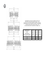
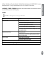
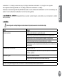
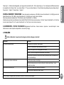
N. di giri della fresa al 1’ (minuto primo) - Motozappe a 3 velocità + 1 RM
Cultivator RPM - Motor driven rotary cultivator with 3 speeds + 1 reverse
Revoluciones por minuto de la fresa - Motoazada de 3 velocidades + 1 marcha atrás
Fräsenumdrehungen pro Minute - Motorhacken mit 3 Vorwärts - und 1 Rückwärstgang
N. de tours de la fraise par minute - Motohoues à 3 vitesses + 1 MA
Nº de rotações da fresa por minuto – Motoenxadas com 3 velocidades + 1 MA
N. giri max motore al 1’
Max engine rpm
RPM
Max Motordrehzahl
N. de tours max engine par minute
N. máx. de rotações do motor por min.
I marcia
I st gear
I marcha
1. Gang
I marche
I velocidade
II marcia
II st gear
II marcha
2. Gang
II marche
II velocidade
III marcia
III st gear
III marcha
3. Gang
III marche
III velocidade
3.000 32,31 108,09 143,76
3.600 38,77 129,71 172,51

8Velocità di marcia in km/h - Motozappe a 3 velocità + 1 RM
Driving speed in kph - Motor driven rotary cultivator with 3 speeds + 1 reverse
Velocidad en km/h - Motoazada de 3 velocidades + 1 marcha atrás
Fahrgeschwindigkeit in km/h - Motorhacken mit 3 Vorwärts + 1 Rückwärtsgang
Vitesse de marche en km/h - Motohouse à 3 vitesses + 1 MA
Velocidade de marcha em km/h - Motoenxada com 3 velocidades + 1 MA
Pneumatici
Tyres
Neumáticos
Bereifung
Pneumatique
Pneus
I marcia
Ist gear
I marcha
1. Gang
I marche
I velocidade
II marcia
IInd gear
II marcha
2. Gang
II marche
II velocidade
III marcia
IIIrd gear
III marcha
3. Gang
III marche
III velocidade
RM
Rev
RPM
Rückwärtsgang
MA
Marcha atrás
5.00-10 2,98 9,97 13,27 2,98
5.00-10 3,58 11,97 15,92 3,58
Motore con regime massimo 3000 giri/1’
Max engine Rpm: 3000
Motor con regimen max. de 3000 RPM
Motor mit max. drehzahl von 3.000 U/min
Moteur à plein regime de 3000 tours
Motor com regime máximo a 3000 rpm
Motore con regime massimo 3600 giri/1’
Max engine Rpm: 3600
Motor con regimen max. de 3600 RPM
Motor mit max. drehzahl von 3.600 U/min
Moteur à plein regime de 3600 tours
Motor com regime máximo a 3600 rpm

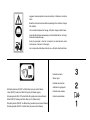
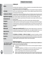
Indicazione marce
Sticker: gear
Indicador de marchas
Aufkleber zur gangwahl
Indication des vitesses
Indice de velocidades
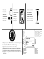
Etichetta posizione ON-OFF su Motor Stop (solo per motori Diesel)
Label ON-OFF position on Motor Stop (only for Diesel engine)
Etiqueta posición ON- OFF sobre Motor-Stop (sólo para motores Diesel)
Etikett ON-OFF stellung auf Motor Stop (nur für Diesel motor)
Etiquette position ON-OFF sur Motor-Stop (seulement pour moteurs Diesel)
Etiqueta posição ON-OFF no Motor Stop (só para motores Diesel)
Leggere il manuale prima di usare la macchina - Attenzione: rotazione
fresa.
Read the instructions manual before operating on the machine - Danger
tiller rotation.
Lire le mode d'emploi avant l'usage - Attention: danger rotation fraise.
Lesen Sie die Gebrauchsanweisung vor der Inbetriebnahme - Achtung:
drehende Hackwerkzeuge.
Antes de proceder a montar la màquina lea atentamente estas
instrucciones - Atencion: la fresa gira.
Ler o manual das instruções antes do uso - Atenção: rotação da fresa.

Retromarcia
Reverse drive
Marcha atrás
Rückwärtsgang
Marche arrière
Marcha atrás
1
Costruttore
Manufacturer
Constructor
Hersteller
Constructeur
Fabricante
2
Modello
Type
Modelo
Modell
Modèle
Modelo
3
Anno di costruzione
Year of construction
Año de construcción
Baujahr
Année de construction
Ano de fabricação
4
Numero di serie articolo – Progressivo
Serial number - Progressive
Número de serie artículo – Progresivo
Serienummer - fortlaufend
Numéro de série article - Progressif
Numero de série - Progressivo
5
Massa
Mass
Masa
Gewicht
Masse
Massa
6
Potenza in kW
Power in kW
Potencia en kW
Leistung in kW
Puissance en kW
Potência em kW
Obbligatorio portare le cufe di protezione acustica durante la zappatura.
Acoustic protection muffs must be worn when mowing.
Obligatorio llevar protectores de oido durante el trabajo.
Während der Arbeit ist das Tragen von Gehörschutz vorgeschrieben.
Port obligatoire du casque de protection de l’ouïe pendant le binage.
É obrigatório o uso de protectores auriculares durante o trabalho com a
motoenxada.
Innesto frizione
Clutch connection
Embrague
Einkuppeln
Embrayage
Embraiagem
Etichetta acceleratore
Label accelerator
Etiqueta acelerador
Aufkleber - Gashebel
Plaquette acceleration
Plaqueta do acelerador

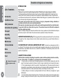
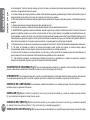
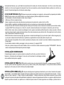
INTRODUZIONE
Gentile cliente, la ringraziamo per la ducia accordata ai ns. prodotti e le auguriamo un piacevole utilizzo della
sua macchina.
Abbiamo creato queste istruzioni per I’uso allo scopo di assicurare, n dall’inizio, un funzionamento privo
d’inconvenienti. Seguite attentamente questi consigli, avrete la soddisfazione di possedere per molto tempo
una macchina che funziona a dovere.
Le nostre macchine, prima di essere fabbricate in serie, vengono collaudate in maniera molto rigorosa e, durante
la fabbricazione vera e propria, sono sottoposte e severi controlli. Ciò costituisce, per noi e per voi, la migliore
garanzia che si tratta di un prodotto di riprovata qualità.
Questa macchina é stata sottoposta a rigorosi test neutrali, nel paese d’origine, e risponde alle norme di
sicurezza in vigore.
Per garantire questo, é necessario utilizzare esclusivamente ricambi originali.
L’utilizzatore perde ogni diritto di garanzia qualora vengano utilizzati ricambi non originali.
Con riserva di variazioni tecnico-costruttive.
Per informazioni e per ordinazioni di pezzi di ricambio si prega citare il numero di articolo e il numero di
produzione.
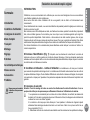
n Dati per l’identicazione (Fig. 1) L’etichetta con i dati della macchina e il numero di matricola è sul
anco sinistro della scatola cambio. Nota - Nelle eventuali richieste di Assistenza Tecnica o nelle ordinazioni
delle Parti di Ricambio, citare sempre il numero di matricola della motozappa interessata.
n Condizioni di utilizzazione - Limiti d’uso La motozappa è progettata e costruita per eseguire
operazioni di zappatura del terreno. La motozappa deve lavorare esclusivamente con attrezzi e con ricambi
originali. Ogni utilizzo diverso da quello sopra descritto è illegale; comporta, oltre al decadimento della garanzia,
anche un grave pericolo per l’operatore e per le persone esposte.
n Norme di sicurezza
Attenzione: prima del montaggio e la messa in funzione leggere attentamente il libretto istruzione. E’ vietato
l’utilizzo a persone non adeguatamente addestrate sull’uso della macchina.
1 - L’ uso della macchine è vietato ai minori di 16 anni e alle persone che hanno assunto alcol, medicine
o droghe.
2 - La macchina è stata progettata per essere utilizzata da un solo operatore addestrato.
L’utilizzatore dell’apparecchio è responsabile di danni arrecati ad altre persone ed alle loro proprietà;
controllare che altre persone, sopratutto i bambini stiano lontani dalla zona di lavoro (10 metri).
3 - Togliere i corpi estranei dal terreno prima di iniziare le operazioni di fresatura . Lavorare solo alla luce
del giorno oppure in presenza di una buona illuminazione articiale.
ITALIANO
1
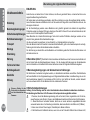
Indice
Introduzione
Condizioni di utilizzazione
Suggerimenti di sicurezza
Istruzioni d’ uso
Trasporto
Montaggio
Regolazione
Manutenzione
Dati tecnici
Rumore aereo
Accessori
Guasti
Pericolo grave per
l’incolumità dell’operatore e
delle persone esposte.
Istruzioni d’uso originali

ITALIANO
2
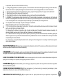
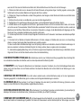
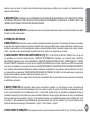
4 - Non mettere in moto la macchina quando si è davanti alla fresa, né avvicinarsi ad essa quando è in moto. Tirando la corda di avviamento
del motore, le frese e la macchina stessa devono rimanere ferme (se le frese girano intervenire sul registro di regolazione del tendi-cinghia).
5 - Durante il lavoro, per maggiore protezione, vanno indossate calzature robuste e pantaloni lunghi. Fare attenzione, perchè il pericolo di
ferirsi le dita o i piedi con la macchina in funzione, è molto elevato. Camminare, non correre, durante il lavoro.
6 - Durante il trasporto della macchina e tutte le operazioni di manutenzione, pulitura, cambio degli attrezzi, il motore deve essere spento.
7 - Allontanarsi dalla macchina non prima di aver spento il motore.
8 - Non avviare la macchina in locali chiusi dove si possono accumulare esalazioni di carbonio.
9 - AVVERTENZA La benzina è altamente inammabile, conservare il carburante in appositi recipienti. Non fare il pieno di benzina in locali
chiusi né con il motore in moto. Non fumare e fare attenzione alle fuoriuscite di combustibile dal serbatoio. In caso di fuoriuscita non tentare di
avviare il motore, ma allontanare la macchina dall’area interessata evitando di creare fonti di accensione nché non si sono dissipati i vapori
della benzina. Rimettere a posto correttamente i tappi del serbatoio e del contenitore della benzina. Non aprire il tappo della benzina con
motore acceso o quando è caldo.
10 - Attenzione al tubo di scarico. Le parti vicine possono arrivare a 80°. Sostituire i silenziatori usurati o difettosi.
11 - Non lavorare sui pendii eccessivamente ripidi ed usare la massima precauzione nell’invertire il senso di marcia o nel tirare verso sé stessi
la macchina.
12 - Prima di iniziare il lavoro con la macchina procedere ad un controllo visivo e vericare che tutti i sistemi antinfortunistici, di cui essa è
dotata, siano perfettamente funzionanti. E’ severamente vietato escluderli o manometterli. Sostituire le lame danneggiate o usurate per lotti
campione per mantenere il bilanciamento.
13 - Ogni utilizzo improprio, le riparazioni effettuate da personale non specializzato o l’impiego di ricambi non originali, comportano il
decadimento della garanzia e il declino di ogni responsabilità della ditta costruttrice.
14 - Nel caso si utilizzino le ruote di trasporto, dall’area di lavoro al magazzino di stoccaggio, occorre inserire le marce più basse in modo da
ridurre la velocità.
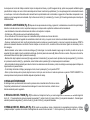
n DISPOSITIVO DI SICUREZZA (Fig. 6) Tutte le motozappe sono dotate di dispositivo antinfortunistico. Detto dispositivo causa il disinnesto
automatico della trasmissione quando si rilascia la relativa leva di comando (8).
n TRASPORTO Per la movimentazione è previsto l’uso di carrello elevatore. Le forche, allargate al massimo consentito, vanno inserite negli
appositi spazi del pallet. La massa della macchina è indicata nella etichetta della marcatura e riportata nei dati tecnici.
n MONTAGGIO DELLA MOTOZAPPA La motozappa viene consegnata a destinazione, salvo accordi diversi, smontata e sistemata in un
adeguato imballaggio. Per completare il montaggio della motozappa osservare la seguente procedura.
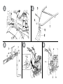
n MANUBRIO (Fig. 2) Fissare il manubrio di guida (1) al supporto (2) tramite la leva (3), il dado con rondella (4) infrapponendo lo snodo (5) con
i denti della regolazione rivolti verso l’operatore.
n BRACCIO DEL TIMONE E TIMONE (Fig. 3) Posizionare il braccio del timone (1) al porta braccio (2), bloccare con il perno (3) e la spilla
di sicurezza (4). Inlare il timone (5) nella parte terminale del braccio (1), bloccare con il perno (6) e la spilla (7).

n MONTAGGIO DELLE FRESE A ZAPPETTE (Fig. 4) L’albero porta-frese è realizzato con un prolo esagonale per consentire la
sostituzione rapida degli attrezzi in funzione del lavoro da eseguire. Pulire i mozzi delle frese e il prolo esagonale dell’albero; spalmare una piccola
quantità di grasso per facilitare il montaggio e la futura rimozione delle frese. Inlare il mozzo delle frese (1) all’albero esagonale della motozappa
tenendo presente che: la parte tagliente delle zappette deve essere rivolta verso l’avanti della motozappa; il foro praticato sul mozzo della fresa
deve corrispondere con il foro dell’albero esagonale della motozappa. Bloccare la fresa a zappette all’albero della motozappa mediante la vite (2), la
rondella (3) e il dado (4). Procedere in modo analogo per il montaggio dell’altra fresa a zappette.
n USO DELLA MOTOZAPPA (Fig. 6) Dopo le operazioni di montaggio e regolazione la motozappa è pronta per lavorare. ATTENZIONE
prima di avviare il motore controllare sempre che la macchina sia in perfette condizioni di funzionamento.
- Leggere attentamente il libretto istruzioni allegato del relativo motore.
- Controllare che il ltro aria sia ben pulito.
- Riempire il serbatoio di carburante del tipo indicato dalle speciche nel libretto del motore, usando un imbuto con il ltro.
- Non modicare la taratura del regolatore di velocità del motore e non far raggiungere ad esso una condizione di elevata velocità.
- Messa in moto del motore Aprire il rubinetto del carburante (per i motori provvisti) e posizionare su START la levetta dell’acceleratore posta sulla
stegola. Per la partenza con il motore a freddo consultare il libretto del motore. Afferrare la maniglia di avviamento e dare uno strappo energico.
- Marcia avanti: muovere l’asta cambio (3) sino a posizionarsi nella marcia desiderata, quindi impugnare le stegole e sollevare il fermo di sicurezza
(A) che impedisce l’innesto accidentale delle frese. Premere la leva avanzamento (B) per tutta la sua corsa. Per innestare una marcia differente è
necessario prima rilasciare la leva avanzamento B.
- Marcia indietro: rilasciare la leva avanzamento (B), quindi posizionare l’asta cambio (3) nella posizione di folle. Premere il fermo di sicurezza (C) e
tirare verso di sé la leva di retromarcia (D), mantenendola premuta innestare anche la leva (B). A questo punto la macchina inizierà a retrocedere.
- Fine lavoro: terminato il lavoro, per arrestare il motore, portare la levetta (1) nella posizione STOP.
Nota. Al primo avviamento della giornata lasciare girare il motore per qualche minuto con tutte le leve in posizione FOLLE. E’ buona norma osservare
questa precauzione anche dopo il periodo di rodaggio.
n REGOLAZIONE DELLA FRIZIONE
La frizione deve staccare solo quando la leva del manubrio si trova a ne corsa.
Vericare periodicamente il corretto funzionamento, nel caso rivolgersi ad un centro
di assistenza, per la messa a punto.
n REGOLAZIONE DEL TIMONE (Fig. 3) Per ottenere una buona fresatura e un avanzamento regolare della motozappa, è necessario
regolare il timone (5) 1. Zappatura leggera: estrarre la spina di sicurezza (7) slare il perno (6) e abbassare il timone (5) no alla posizione desiderata.
2. Zappatura profonda: estrarre la spina di sicurezza (7) slare il perno (6) e alzare il timone (5) no alla posizione desiderata.
n REGOLAZIONE DEL MANUBRIO (Fig. 6) Il manubrio di guida è orientabile sia lateralmente che in altezza. E’ consigliabile prima di
iniziare qualsiasi tipo di lavoro, adattare la posizione del manubrio alle esigenze dell’operatore per rendere la motozappa facilmente manovrabile.
1 - Ruotare in senso antiorario la leva (5). 2 - Regolare il manubrio nella posizione desiderata. 3 - Bloccare nuovamente il manubrio ruotando la leva
ITALIANO
3

ITALIANO
4
(5) in senso orario (accertarsi che i denti dello snodo siano perfettamente innestati). La macchina è congurata per lavorare con i manubri orizzontali
rispetto al piano ed in asse con il telaio della macchina. Per ragioni ergonomiche e di utilizzo è tuttavia possibile inclinarla lateralmente ed in altezza.
Occorre prestare attenzione se si lavora in queste congurazioni, in quanto si riduce la distanza tra la posizione di guida e gli utensili in rotazione.
n MANUTENZIONE NON ATTENDERE CHE I COMPONENTI DELLA MOTOZAPPA SIANO LOGORATI DALL’USO, PRIMA DI
PROCEDERE ALLA LORO SOSTITUZIONE. INTERVENIRE IN TEMPO SIGNIFICA UN MIGLIOR FUNZIONAMENTO DELLA MACCHINA E
CONTEMPORANEAMENTE UN RISPARMIO, DOVUTO AL FATTO CHE SI EVITANO DANNI MAGGIORI.
n MANUTENZIONE DEL MOTORE Le prescrizioni per l’uso e la manutenzione del motore sono contenute nel rispettivo libretto, copia del
quale viene fornita con ogni motozappa.
n OPERAZIONI DI SERVIZIO
n RIMESSAGGIO Mantenere serrati tutti i dadi, i bulloni e le viti per garantire il funzionamento della macchina nelle condizioni di sicurezza. Lasciar
raffreddare la macchina prima di immagazzinarla e comunque non riporla con benzina nel serbatoio all’interno di un edicio, dove i vapori possono
raggiungere una amma libera o una scintilla. Svuotare il serbatoio all’esterno. Per ridurre il pericolo di incendio mantenere il motore, il silenziatore e
la zona di immagazzinamento della benzina liberi da foglie, erba e grasso in eccesso.
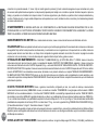
n CAPACITÀ E PUNTI DI RIFORNIMENTO (Fig. 5) 1- FILTRO ARIA MOTORE 4T-DIESEL Per il tipo di olio e la capacità (vedi libretto
motore). 2 - SERBATOIO COMBUSTIBLE Capacità - vedi libretto motore. 3 - SCATOLA CAMBIO Capacità Kg 2.5 usare olio SAE 85/90 W. 4 - ASTA
LIVELLO OLIO - TAPPO DI SFIATO. 5 - COPPA OLIO MOTORE Capacità - vedi libretto motore. SCATOLA DEL CAMBIO: dopo 100 ore: cambiare
l‘olio. AVVERTENZA Le motozappe nuove sono lubricate con i prodotti indicati nelle OPERAZIONI DI SERVIZIO. NON MISCELARE FRA LORO
PRODOTTI DIVERSI; per l’impiego di lubricanti diversi da quelli prescritti, scaricare completamente l’olio esistente ed usare esclusivamente i
prodotti corrispondenti. ORGANI MECCANICI PER LE PRIME 80 ORE: controllare frequentemente la sicurezza di ssaggio dei vari organi (se
necessario, serrare accuratamente viti, dadi, ecc.)
IMPORTANTE! Per evitare l’inquinamento delle falde acquifere, l’olio esausto non deve essere gettato in scarichi fognari o canali idrici. Depositi
per l’olio esausto sono ubicati presso tutti i distributori di benzina, oppure in discariche autorizzate secondo le normative comunali del Comune di
residenza.
n DATI TECNICI Motore: Diesel, a benzina, monocilindrico, raffreddato ad aria, con avviamento a strappo, con autoavvolgente (vedi libretto
motore). Frizione: a secco con comando sulla stegola di guida. Trasmissione: ad ingranaggi in bagno d’olio. Cambio: a 3 velocità in avanti + 1
retromarcia. Presa di potenza: a velocità ssa, indipendente dal cambio. Presa di potenza: sincronizzata con il cambio. Manubrio di guida: registrabile
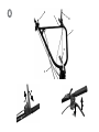
lateralmente ed in altezza, con possibilità di bloccaggio rapido in tutte le posizioni. Fresa (Fig. 7): a zappette intercambiabili, con possibilità di
larghezza di lavoro da 61 a 125 cm. (in gura n.7 sono indicate le varie possibilità di composizione della fresa). Peso: con motore Diesel Kg. 111, con
motore a Benzina Kg. 95. Pressione di gonaggio dei pneumatici (Fig.8): Pneumatici Anteriori: 1,2 kg./cm2 - Pneumatici Posteriori: 1,6 kg./cm2.
n RUMORE AEREO E VIBRAZIONI: Valore di pressione acustica al posto di lavoro secondo EN 709 Leq= 90,9 dB (A), valore d’incertezza
nella misura K = ± 1,3 dB(A) per mod. con motore diesel; 83,1 dB (A), K = ±1,2 per mod. con motore a benzina. Valore di potenza acustica secondo

ITALIANO
5
En709 Lwa = 104,4 dB(A), valore d’incertezza nella misura K = ±1,5 dB(A). Vibrazioni alle stegole secondo EN 709 e ISO 5349= 8,2 m/s2, valore
d’incertezza nella misura K = ±4,1 m/s2 per mod. con motore diesel; 7,5 m/s2, K = ±3,7 m/s2 per mod. con motore a benzina.
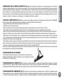
n ACCESSORI - ATTREZZI UTILIZZABILI Allargamento fresa - aratro monovomere, assolcatore - ruote di trasferimento - ruote motrici
con o senza cricchetto compensatore - ruote in ferro (a gabbia).
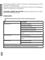
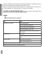
n GUASTI
Prima di effettuare qualsiasi operazione, staccare il cappuccio della candela !
Guasto Rimedio
Il motore non si avvia Carburante esaurito, fare rifornimento.
Controllare che l’acceleratore sia posizionato su START.
Controllare che il cappuccio candela sia ben inserito.
Controllare lo stato della candela ed eventualmente sostituire.
Controllare che il rubinetto del carburante sia aperto (solo per i modelli di motore
in cui è previsto il rubinetto).
La potenza del motore diminuisce Filtro aria sporco, pulirlo.
Controllare che sassi o residui di terra e vegetazione non frenino la rotazione
delle frese, nel caso rimuoverli.
Le frese non ruotano Regolare i registri del cavo trasmissione.
Controllare che le frese siano ssate all’albero.
Nel caso non si riesca a porre rimedio al guasto, rivolgersi ad un centro di assistenza autorizzato.

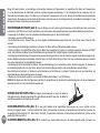
INTRODUCTION
Dear Customer:
Thank you for your trust in purchasing our products. We wish you to enjoy using our machines.
The following working instructions have been issued to ensure reliable operating from the beginning. If you
carefully follow such information the machine will operate with complete satisfaction have a long service life.
Our machines are tested under the most severe conditions before being put into production and are subject to
strict continuous tests during manufacturing stages.
This present unit has been tested in the country of origin by independent testing authorities in
accordance with strict work norms and safety standards.
When required, only original spare parts must be used to maintain guaranteed function and safety levels.
The operator forfeits any claims which may arise, if the machine shows to be tted with components
other than original spare parts.
Subject to changes in design and construction without notice. For any questions or further information and spare
part orders,we need to be informed of the unit serial number printed on the side of the machine.
n IDENTIFICATION DATA (Fig. 1) The tag plate with the machine data and Serial N° is on the left side
of the gear box. Note - Always state your motor cultivator serial number when you need Technical Service or
Spare Parts.
n CONDITIONS OF USE AND LIMITATIONS OF USE This motor-hoe is designed and built to
hoe the land. The motor-hoe must only be used with original equipment and spares. Any use other than that
described above is prohibited and will involve, in addition to cancellation of the warranty, serious risk for the
operator and bystanders.
n SAFETY PRECAUTIONS
Attention: Before assembly and putting into operation, please read the operating instruction carefully.
The use of the machine is forbidden for people who are not adequately trained .
1- Persons who are not familiar with the operating manual, as well as children, adolescents under the
age of 16 and persons under the inuence of alcohol, drugs or medication must not operate the mower.
2 - The unit was designed in order to be used by 1 trained operator only. The person using the mower is
responsible for any accidents involving other persons or their property. When operating the machine, the
user should ensure that no others, particularly children, are standing in the area (10 mt.).
3 - Before starting to mill, remove any foreign bodies from the soil. Work only in daylight or in good
articial light.
4 - Do not start the machine if standing in front of the rotary cutter, neither get near the machine when
working. If pulling the starter short rope, the rotary cutter and the machine have to standstill (if rotation
ENGLISH
6
List of contents
Introduction
Conditions of use
Safety measures
Instructions for operating
Transport
Assembly
Regulating
Maintenance
Technical Details
Noise
Accessories
Fault
Serious risk for operator
and bystander safety.
Translation of original user instructions

ENGLISH
7
is experienced, take action on the belt stretcher control nut).
5 - During working operations, for protection purposes, it is recommended to wear technical/strong shoes and long trousers. Be careful ,
because when machine is operating the danger to be wounded in the toes or feet is really high. Walk, never run with the machine.
6 - During the machine transport and all the maintenance, cleaning, equipment change operations, the engine must be switched off.
7 - Before leaving the machine, please switch the engine off.
8 - Do not switch the machine on in closed rooms/areas where you can have carbon monoxide exhalations.
9 - WARNING !! The petrol/gasoline is highly inammable: Don’t ll the tank neither in closed areas, nor when engine is on, don’t smoke and
be careful to the petrol/gasoline loss from the tank. In case of leak, don’t try to switch the engine on but move the machine away from the area
in order to avoid ignition source until the gasoline vapours fade away. Re-place the tank caps and the gasoline box.
10 - Keep attention to the exhaust pipe. The parts near the pipe can reach 80°C.
Replace the defective and/or worn out silencers Burn hazards !!!.
11- Don’t use the motor hoe on steep slopes: it could overturn!. On slope it is recommended to work crosswise, neither in slope nor in descent
and be vary careful during any change of direction.
12 - Before putting the machine into operations, check it visually and make sure all the accident prevention measures are working. It is
absolutely forbidden to exclude and/or to tamper with them. Replace worn or damaged elements.
13 - In case the machine is incorrectly used, and/or the repairs are performed by non-authorized technical staff, and/or tted by spare parts
other then original ones: any use other than that described above is prohibited and will involve the cancellation of the warranty and the refuse
all responsibility from the manufacturer.
14 - In the case you are using the transport wheels, from the working area to the storage place, it is necessary to insert the lower gears in
order to reduce the speed.
n SAFETY FEATURE (Fig. 6) All motor-hoes are provided with a safety feature which acts. The device causes the transmission to disconnect
automatically anytime the respective control lever is released (8).
n TRANSPORT A forklift truck should be used to move the machine. The forks should be opened as far as possible and inserted into the pallet.
The weight of the machine is given on the Manufacturer’s data plate together with the other technical information.
n HOW TO ASSEMBLE YOUR MOTOR-HOE Unless otherwise agreed, the motor cultivator is delivered disassembled and placed in a
packing case. For assembly to be completed, the step/by/step procedure is as follows.
n HANDLEBAR (Fig. 2) Attach the handlebar (1) to its mounting (2) using link-rod (3) washer and nut (4) and the swivel between (5) with the
teeth turned towards the operator.
n DRAW BAR ARM AND DRAWBAR (Fig. 3) Place the drawbar arm (1) on the arm carrier (2), lock with pin (3) and safety pin (4). Insert
drawbar (5) into the arm end (1), secure with the pin (6) and safety pin (7).
n MOUNTING THE HOE-TILLER (Fig. 4) The implement shaft hex. shaped prole allows for quick replacement of implements in

accordance with the job to be performed. Clean thoroughly the tiller hubs and the hex. shaft section; applicate some grease to make mounting and
tiller future removal easier. Fit the tiller hub (1) to the hex. motor-hoe tiller shaft. Make sure that: the cutting edge of the small hoes is towards the
machine FRONT the bore on tiller hub matches the hole of the motor-hoe hex. shaft. Fasten the tiller to the motor-hoe shaft by means of screw (2),
washer (3) and nut (4). For mounting the other tiller, follow the same procedure as laid down.
n USING THE ROTARY CULTIVATOR (Fig. 6) : after the assembly and adjusting operations the tiller is ready to be used. ATTENTION !
before swtching the engine on , please carefully check the unit to be in good working conditions.
- carefully read the instructions booklet you can nd with the engine
- check the air lter to be very well cleaned
- ll the tank in using the kind of fuel that is specied in the engine instructions booklet, using a funnel equipped with lter.
- Do not modify the calibration of the engine speed adjuster and do not allow it to reach high speed.
- How to switch the engine on : open the fuel cock ( for the engines equipped with it ) and put the throttle lever ( you can see on handlebar ) on START
position. In case you need to switch the engine on at cold conditions, please read the engine instructions booklet. Grasp the switching on handle and
give a strong pull to it.
- Forward speed: move the shift rod (3) until the desired gear position, then grip the handles and lift the safety catch (A) that prevents accidental
engagement of the tines. Push the lever forward (B) for its entire run. To engage a different gear you must rst release the forward lever B.
- Reverse gear : release the lever forward (B), then position the shift rod (3) in the neutral position. Press the safety pin/lock (C) and pull towards the
reverse lever (D), keeping it pressed the lever also insert lever(B). At this point the machine will start to move reverse direction.
- The present tiller has been designed to reduce the noise and vibration emissions to their minimum levels but we recommend to suspend a long work
with some short breaks.
- End of the work : once you have ended your work , in order to stop the engine , bring the lever (1) on STOP position .
- NOTE : during the rst switch on of the day, please let the engine turn for some minutes keeping all the levers on NEUTRAL position. It is also
recommended to perform the a.m. operation even after the running in period.
n CLUTCH ADJUSTMENT The clutch control must be disengaged only when the handlebar lever is
end all its way. We recommend to verify the correct working from time to time, in case it is not correct please
apply to an authorized servicing centre for the adjustment.
n ADAPTING THE DRAWBAR (Fig. 3) To obtain a smooth forward movement and a good job, adjust as follows: 1. On soft soils: remove
shaped safety pin (7); take out lock pin (6) and lower drawbar (5) until the position desired. 2. On hard soils: remove shaped safety pin (7), take out
lock pin (6) and raise drawbar (5) to the position desired.
n ADJUSTMENT OF THE HANDLE BAR (Fig. 6) The handlebar provides for being aligned both sideways and in vertical in a few
positions. Prior to undertaking any job, it is recommended the handlebar be adated to the operator for easier handling any time. 1. Rotate lever (5),
counterclockwise for lock be released. 2. Set handlebar in the position desired (sideways and vertical adjustment are obtaind at the same time). 3.
ENGLISH
8

Have handlebar locked again through clockwise rotation of lever (5), and make certain that teeth mesh accurately. The unit is intended to be used
in an upright manner with the handlebars in a horizontal position in relation to the plane of the earth and in axis with the frame of the machine. For
ease of use in some conditions it is possible to adjust the unit’s handlebar (side / up or down). However, please be careful if you are working in any
such adjusted conguration as the distance between the operator and the rotation tools becomes shorter, and thus presents a greater risk of injury.
n MAINTENANCE DO NOT WAIT UNTIL THE ROTARY CULTIVATOR PARTS ARE COMPLETELY WORN FROM USE BEFORE CHANGING
THEM. SERVICING THE MACHINE IN GOOD TIME WILL GREATLY IMPROVE MACHINE PERFORMANCE AND WILL ALSO SAVE YOU MONEY
SINCE COSTLY MAJOR REPAIRS CAN BE AVOIDED.
n ENGINE MAINTENANCE Engine operating and maintenance instructions are given in the Engine Manual supplied with each rotary
cultivator.
n SERVICING OPERATIONS
n GARAGING AND SCHEDULED MAINTENANCE Keep attention that all the nuts, screws and bolts are tightened in order to guarantee
a good machine working on safety conditions. Leave the machine to cool before garaging anyhow don’t room it if the tank still contains some fuel as
the vapours could reach some blazes or sparks. The fuel tank is to be drained outdoors only. To lower the re danger , keep the engine, the silencer
and the fuel area free from leaves , grass or greasy substances.
n FUEL AND OIL CAPACITY AND FILLING POINTS (Fig. 5) 1) Engine air lter 4T-DIESEL. Refer to the engine manual for the type
and amount of oil. 2) Fuel tank: capacity: capacity - refer to engine manual. 3) Gearbox: capacity: 2.5 kg; use SAE 85/90 W oil; 4) Oil level dipstick;
vent plug; 5) Engine crankcase: capacity - refer to engine manual.
Gearbox: after 100 hours: change the oil. IMPORTANT! New rotary cultivators are lubricated using the types of oil listed in the section on SERVICING
OPERATIONS. DO NOT MIX DIFFERENT TYPES OF OIL. If you have to use lubricants other than those listed, completely drain the oil contained
and make sure the lubricants selected strictly comply with the characteristics of the original oils. Mechanisms: during the rst 80 hours: frequently
check for proper and safe clamping of the mechanisms (tighten down screws, nuts etc. as necessary).
ATTENTION! The used oil must not be drained into the sewer system or waterworks. In order to prevent any pollution to the water-table. Most garages
have used oil deposits, or use the authorized deposits according to your local authority regulations.
n TECHNICAL SPECIFICATION Engine: diesel, petrol, single cylinder, air cooled, self-winding pull starter (refer to Engine Manual). Clutch:
dry single-disc type, lever-controlled from the handlebars. Transmission: all gears in oil Gearbox: 3 forward speeds + 1 reverse with safety device.
PTO: xed speed; gearbox independent. PTO: synchronized with gearbox Handlebars: sideways and height adjustment, quick lock in any positions.
Tiller (Fig.7): tted with interchangeable hoes. Working width 61 to 125 cm. Provided with protection hood. The working width range being obtained
by adding or removing hoes are shown in gure 7. Weight: with diesel engine: 111 kg; with petrol engine: 95 kg. Tyre ination pressure (Fig. 8): front
wheels: 1.2 kg/cm2; rear wheels: 1.6 kg/cm2.
n NOISE AND VIBRATION LEVEL Measured sound power level with En709, Lwa = 104,4 dB (A), with a uncertainty value K = ±1,5 dB (A).
ENGLISH
9

ENGLISH
10
Measured sound pressure level with En709, Leq = 90,9 dB (A), with a uncertainty value K = ±1,3 dB (A) with diesel engine and Leq = 83,1 dB (A),
with a uncertainty value K = ±1,2 dB (A) with petrol engine.
Handlebar vibration in compliance with EN 709 and ISO 5349. Level max detected = 8,2 m/s2, uncertainty value K = ±4,1 m/s2 with diesel engine; level
max detected = 7,5 m/s2, uncertainty value K = ±3,7 m/s2 with petrol engine.
n ACCESSOIRES - IMPLEMENTS THAT CAN BE USED Cultivator expansion - single share ploughs - furrower - on-road wheels -
drive wheel with or without compensating jack - cage wheels.
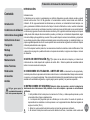
n TROUBLESHOOTING
Before performing any maintenance and clearing work operation , please take the spark-plug cap off.!
FAULT FAULT CLEARANCE
The engine does not start Check the fuel level, if necessary refuel.
Check the throttle to be on START position.
Check the spark-plug connector to be properly attacched.
Check the spark-plug condition and if necessary replace it.
Check the fuel valve to be in the opened position( only for the models showing
such feature).
The engine power goes down The air lter is dirty – please clean it.
Check if any stone or soil/vegetation residue is stopping the tines rotation, in case
clean them.
The tines are not rotating Adjust the transmission cables registers.
Check the tines to be fasten to the shaft.
In case you are not able to remedy the defect/damage according to a.m. table, please contact an authorized service center only .

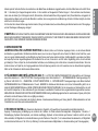
INTRODUCCIÓN
Estimado cliente:
Lo felicitamos por su compra y le agradecemos su conanza. Esperamos que esta máquina sea de su agrado
durante muchos años. Con el n de garantizar un funcionamiento correcto, hemos creado este folleto de
utilización. Si Ud. sigue exactamente las indicaciones que le damos, su motoazada funcionará siempre a su
gusto y permanecerá utilizable durante mucho tiempo. Antes de la fabricación en serie, nuestras motoazadas
son puestas a prueba en las condiciones mas duras; durante el proceso de fabricación se les somete también
a controles muy rigurosos. De este modo tenemos la certeza y Ud. la garantía de obtener siempre una máquina
a toda prueba. Esta máquina ha sido sometida a pruebas y controles por un laboratorio independiente, según
normas de trabajo y de seguridad muy severas. Para que esta máquina conserve las cualidades y proporcione
los resultados previstos, deben utilizarse únicamente piezas de recambio de origen. La calidad de trabajo y su
propia seguridad dependen de ello. El usuano perderá todos sus derechos de garantía si modilica la máquina
utilizando piezas distintas a las originales.
Con el n de mejorar nuestros productos, nos reservamos el derecho de realizar en ellos modicaciones. Para
cualquier tipo de pregunta o pedidos referentes a las piezas de recambio, le rogamos nos indique el número
de referencia.
n DATOS DE IDENTIFICACIÓN (Fig. 1) La placa con los datos de la máquina y el número de la
matrícula está en el lado izquierdo de la palanca de cambio. Nota - Todos los pedidos de recambios deberan
indicar el numero de serie de la máquina.
n CONDICIONES DE UTILIZACION - LIMITES DE USO La motoazada ha sido proyectada y
construida para efectuar operaciones de binadura sobre terrenos. La motoazada debe trabajar exclusivamente
con aperos y con repuestos originales. Todo empleo distinto del descripto precedentemente es ilegal e implica,
además de la caducidad de la garantía, un grave peligro para el operador y las personas expuestas.
n INSTRUCCIONES DE SEGURIDAD Atención: Antes de proceder a montar la máquina lea
atentamente estas instrucciones. Está prohibido el uso de la máquina a personas no correctamente
calicadas
1- Está prohibido utilizar la máquina a los menores de 16 años y a todas aquellas personas que han
consumido alcohol, drogas o medicamentos.
2 - La máquina está proyectada para ser utilizada por un sólo utente. El usuario del aparato es
responsable de los accidentes con otras personas o con la propiedad de éstas. Mantener alejados del
equipo a los niños (10 mt.).
3 - Quitar los cuerpos extraños del terreno antes de iniciar las operaciones de fresado.
4 - No arrancar la máquina cuando se encuentra delante de la fresa, ni acercarse a ésta cuando está
ESPAÑOL
11
Contenido
Introducción
Condiciones de utilizacion
Instrucciones de seguridad
Instrucciones de uso
Transporte
Montaje
Regulacion
Mantenimiento
Datos Técnicos
Ruido aéreo
Accesorios
Averiás
Peligro grave para la
incolumidad del operador y
de las personas expuestas.
Traducción del manual de instrucciones original

ESPAÑOL
12
en funcionamiento. Tirando el cable de arranque del motor, las fresas y la máquina misma deben permanecer paradas (si las fresas giran
intervenir en la regulación del tensor de correa).
5 - Durante el trabajo, para mayor protección, se deben calzar zapatos de seguridad y pantalones largos. Prestar mucha atención, porque el
peligro de heridas en los dedos o en los pies con la máquina en función es muy elevado.
6 - Durante el transporte de la máquina y todas las operaciones de mantenimiento, limpieza, cambio de los aperos, el motor debe encontrarse
apagado.
7 - Alejarse de la máquina únicamente después de haber apagado el motor.
8 - No encender la máquina en ambientes cerrados donde se pueden acumular exhalaciones de carbono.
9 - ADVERTENCIA La gasolina es altamente inamable. Guardar la gasolina en el depósito indicado para este n. No llenar el tanque de
gasolina en ambientes cerrados ni con el motor en funcionamiento, no fumar y prestar atención a las pérdidas de combustible del tanque. En
caso de pérdidas no intentar arrancar el motor, sino alejar la máquina del área interesada evitando crear fuentes inamables hasta que no se
hayan disipado los vapores de la gasolina. Volver a poner correctamente los tapones del tanque y del contenedor de la gasolina. Mientras el
motor está en funcionamiento o la máquina permanece caliente, no repostar gasolina ni abrir el tapón del depósito.
10 - Prestar atención al tubo de escape. Las partes cercanas pueden alcanzar los 80°C. Sustituir los silenciadores desgastados o defectuosos.
11- No utilizar la motoazada en terrenos con declives pronunciados, podría volcarse. En terrenos con declives trabajar siempre
transversalmente, jamás en subida o bajada y observar la máxima cautela en los cambios de dirección.
12 - Antes de iniciar el trabajo con la máquina efectuar un control visivo y vericar que todos los sistemas de prevención de accidentes, que
posee la máquina, funcionen perfectamente. Está absolutamente prohibido excluirlos o adulterarlos.
13 - Toda utilización inapropiada, las reparaciones efectuadas por personal no especializado o el empleo de repuestos no originales,
comportan la caducidad de la garantía y eximen al fabricante de toda responsabilidad.
n DISPOSITIVO DE SEGURIDAD (Fig. 6) Todas las motoazadas están dotadas de un dispositivo contra accidentes. Este dispositivo
provoca la desconexión automática de la transmisión cuando se suelta la relativa palanca de mando (8).
n TRANSPORTE Para el transporte está previsto el uso de una carretilla elevadora. Las horquillas abiertas al máximo permitido, deben inserirse
en los especiales espacios del pallet. La masa de la máquina se indica en la etiqueta de la motoazada y expuesta en los datos técnicos.
n MONTAJE DE LA MOTOAZADA La motoazada se suministra desmontada y en un embalaje apropiado. Para el montaje de la máquina
se deberán seguir las siguientes instrucciones.
n MANILLAR (Fig. 2) Fijar el manillar (1) al soporte (2), con la leva (3), la tuerca con arandela (4), y colocar en el medio la pieza de conexión
(5), con los dientes de la regulación mirando hacía el usuario.
n MONTAJE DEL TIMON (Fig. 3) Posicionar el brazo del timón (1) en su soporte (2), bloquear con el bulón (3) y el pasador de seguridad
(4). Insertar el timón en el extremo del brazo (1) y jar con el bulón (6) y el pasador de seguridad (7).
n MONTAJE DE LAS FRESAS (Fig. 4) El eje del porta-fresas ha sido fabricado con un perl hexagonal para así lograr la sustitucíon rápida
A página está carregando...
A página está carregando...
A página está carregando...
A página está carregando...
A página está carregando...
A página está carregando...
A página está carregando...
A página está carregando...
A página está carregando...
A página está carregando...
A página está carregando...
A página está carregando...
A página está carregando...
A página está carregando...
A página está carregando...
A página está carregando...
A página está carregando...
A página está carregando...
A página está carregando...
A página está carregando...
-
 1
1
-
 2
2
-
 3
3
-
 4
4
-
 5
5
-
 6
6
-
 7
7
-
 8
8
-
 9
9
-
 10
10
-
 11
11
-
 12
12
-
 13
13
-
 14
14
-
 15
15
-
 16
16
-
 17
17
-
 18
18
-
 19
19
-
 20
20
-
 21
21
-
 22
22
-
 23
23
-
 24
24
-
 25
25
-
 26
26
-
 27
27
-
 28
28
-
 29
29
-
 30
30
-
 31
31
-
 32
32
-
 33
33
-
 34
34
-
 35
35
-
 36
36
-
 37
37
-
 38
38
-
 39
39
-
 40
40


EUROSYSTEMS 12 Instruções de operação
- Categoria
- Mini lavradores
- Tipo
- Instruções de operação
em outras línguas
- español: EUROSYSTEMS 12 Instrucciones de operación
- français: EUROSYSTEMS 12 Mode d'emploi
- italiano: EUROSYSTEMS 12 Istruzioni per l'uso
- Deutsch: EUROSYSTEMS 12 Bedienungsanleitung