
WT23L-F430
A
!
B
$
§
-------------------------------------------------------------------------------- 8015428.ZM29 1118 COMAT ------------------------------------------------------------------------------
ENGLISH
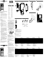
Photoelectric Proximity Sensor
with laser light
Operating Instructions
EN/IEC 60825-1:2014
IEC60825-1:2007
LASERKLASSE 1
Laser
1
Maximum pulse power < 2,0 mW
Puls length: 4,5 µs
Wavelength: 650 nm
Complies with 21 CFR 1040.10
and 1040.11 except for deviations
pursuant to Laser Notice No. 50,
dated June 24, 2007
a
CAUTION: Use of controls or adjustments or performance of
procedures other than those specied herein may result in
hazardous radiation exposure.
Safety Specifications
• Read the operating instructions before starting operation.
• Connection, assembly, and settings only by competent technicians.
• The light beam of the LED may not focused with additional optical
parts.
• Protect the device against moisture and soiling when operating.
• No safety component in accordance with EU machine guidelines.
Proper Use
The WT23L photoelectric retro-reective sensor is an opto electronic
sensor and is used for optical, non-contact detection of objects and
animals.
Starting Operation
!
The WT23L has antivalent switching outputs:
WT23L-F (PNP, load → M):
Q: dark-switching; object is not detected, output HIGH.
Q: light-switching; object is detected, output HIGH.
Select desired operating mode and connect as per connection
diagram B (Q, q).
"
Connect and secure cable receptacle tension-free.
The following apply for connection in B: brn = brown, blu = blue,
blk = black, wht = white.
§
Fix sensor to suitable holders (e.g. SICK mounting bracket).
Maintain direction in which object moves relative to sensor
( Standard direction).
Connect photoelectric proximity sensor to operating voltage (see
type label).
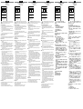
Check application conditions such as sensing distance, size and
reectance of object to be detected as well as of background,
and compare with characteristic in diagram. (x = sensing
distance, y = transition range between set sensing distance and
reliable background suppression (z) in % of sensing distance,
Ro = reectance of object, Rh = reectance of background).
Reectance: 6 % = black, 18 % = gray, 90 % = white (based on
standard white to DIN 5033).
$
Alignment of sensor to the object:
Position object, position light spot on object, red sender light spot
visible on object.
Turn potentiometer to the right; the yellow signal strength indicator
must light continuously. Object is detected reliably.
If required, correct the sensing distance precisely for adaption to
the application conditions: Minimum turn of the potentiometer to
the right: sensing distance is increased. Minimum turn of potenti-
ometer to the left: sensing distance is decreased.
If the yellow signal strength indicator does not light, readjust the
photoelectric proximity switch, clean it and/or check the applica-
tion conditions and then repeat setting.
When the object is removed the signal strength indicator should
not light up. If it still lights up or ashes, the background is
detected. Reduce sensing distance with potentiometer until the
signal strength indicator does not light up any longer.
Maintenance
SICK photoelectric sensors do not require any maintenance. We rec-
ommend that you clean the external lens surfaces and check the screw
connections and plug-in connections at regular intervals.
Modications of devices may not be made.
DEUTSCH
Reexions-Lichttaster
mit Laserlicht
Betriebsanleitung
EN/IEC 60825-1:2014
IEC60825-1:2007
LASERKLASSE 1
Laser
1
Maximale Pulsleistung: < 2,0 mW
Impulsdauer: 4,5 µs
Wellenlänge: 650 nm
Entspricht 21 CFR 1040.10
und 1040.11 mit Ausnahme von
Abweichungen nach
Laser-Hinweis 50, 24. Juni 2007
a
ACHTUNG: Eingrie oder Manipulationen oder nicht bestim-
mungsgemäße Verwendung kann zu gefährlicher Belastung
durch Laser-Lichtstrahlung führen.
Sicherheitshinweise
• Vor der Inbetriebnahme die Betriebsanleitung lesen.
• Anschluss, Montage und Einstellung nur durch Fachpersonal.
• Die Strahlung des Sendelichtes darf nicht durch zusätzliche
optische Bauteile fokussiert werden.
• Gerät bei Inbetriebnahme vor Feuchte und Verunreinigung schüt-
zen.
• Kein Sicherheitsbauteil gemäß EU-Maschinenrichtlinie.
Bestimmungsgemäße Verwendung
Der Reexions-Lichttaster WT23L ist ein opto elektronischer Sensor
und wird zum optischen, berührungslosen Erfassen von Sachen und
Tieren eingesetzt.
Inbetriebnahme
!
Der WT23L hat antivalente Schaltausgänge:
WT23L-F (PNP, Last → M):
Q: dunkelschaltend, Objekt wird nicht erkannt, Ausgang HIGH,
Q: hellschaltend, Objekt wird erkannt, Ausgang HIGH.
Gewünschte Betriebsart laut B anschliessen (Q, Q).
"
Leitungsdose spannungsfrei aufstecken und festschrauben.
Für Anschluss in B gilt: brn = braun, blu = blau, blk = schwarz,
wht = weiß.
§
Sensor an geeignete Halter anschrauben (z.B. SICK-Haltewinkel).
Bewegungsrichtung des Objektes relativ zum Taster einhalten
(Vorzugsrichtung).
Lichttaster an Betriebsspannung legen (s. Typenaufdruck).
Einsatzbedingungen wie Tastweite, Objektgröße und Remissions-
vermögen des Tastgutes sowie des Hintergrundes überprüfen
und mit der Kennlinie im Diagramm vergleichen. (x = Tastweite,
y = Übergangsbereich zwischen eingestellter Tastweite und siche-
rer Hintergrundausblendung (z) in % der Tastweite, Ro = Remission
Objekt, Rh = Remission Hintergrund).
Remission: 6 % = schwarz, 18 % = grau, 90 % = weiß (bezogen
auf Standardweiß nach DIN 5033).
$
Ausrichtung des Sensors auf das Objekt:
Objekt positionieren, Lichteck auf Objekt ausrichten, sichtbarer
roter Sendelichteck auf Objekt erkennbar.
Potentiometer nach rechts drehen, gelbe Empfangsanzeige muss
konstant leuchten: Objekt wird sicher erkannt.
Bei Bedarf Feinkorrektur des Tastabstandes zur Anpassung an
die Applikationsbedingungen: Minimale Rechtsdrehung des
Poti: Tastabstand wird erhöht. Minimale Linksdrehung des Poti:
WT23L -F430
Sensing range
1)
, max. Tastweite
1)
, max. Distance de détection
1)
, max. Raio de exploração
1)
, max. 50 ... 800 mm
Operating distance, adjustable
1)
Betriebstastweite, einstellbar
1)
Distance de détection, réglable
1)
Raio de exploração, ajusável
1)
100 … 800 mm
Light spot diameter/distance Lichtfleckdurchmesser/Entfernung Diamètre de la tache lumineuse/distance Diâmetro do ponto de luz/distância 2 mm/400 mm
Supply voltage V
S
2)
Versorgungsspannung U
V
2)
Tension d'alimentation U
V
2)
Tensão de força U
V
2)
10 ... 30 V DC
Output current I
max
Ausgangsstrom I
max.
Courant de sortie I
maxi
Corrente de saída I
máx.
100 mA
Switching frequency Schaltfrequenz
3)
Fréquence de commutation Frequência de ligação 50 Hz
Response time
4)
Ansprechzeit
4)
Temps de réponse
4)
Tempo de reação
4)
25 ms
Enclosure rating Schutzart Type de protection Tipo de proteção IP 65
Protection class
5)
Schutzklasse
5)
Classe de protection
5)
Classe de proteção
5)
Circuit protection
6)
Schutzschaltungen
6)
Circuits de protection
6)
Circuitos protetores
6)
A, B, C
Ambient operating temperature Betriebsumgebungstemperatur Température ambiante Temperatura ambiente de operação –10 … +45 °C
1)
Object 90 % reflection according to DIN 5033
2)
Limits
Residual ripple max. 5 V
PP
Operation in short-circuit protected network max. 8 A
3)
With light/dark ratio 1:1
4)
Signal transit time with resistive load
5)
Reference voltage 50 V DC
6)
A = V
S
connections reverse polarity protected
B = Outputs protected against short circuits
C = Interference pulse suppression
1)
Objekt 90 % Remission nach DIN 5033
2)
Grenzwerte
Restwelligkeit max. 5 V
SS
Betrieb im kurzschlussgeschützten Netz max. 8 A
3)
Bei Hell/Dunkelverhältnis 1:1
4)
Signallaufzeit bei ohmscher Last
5)
Bemessungsspannung DC 50 V
6)
A = U
V
-Anschlüsse verpolsicher
B = Ausgänge kurzschlussfest
C = Störimpulsunterdrückung
1)
Objet Luminance de 90 % selon DIN 5033
2)
Valeurs limites Ondulation résiduelle maxi 5 V
SS
Service dans un réseau protégé contre les courts-circuits 8 A au maximum
3)
Pour un rapport clair/sombre 1:1
4)
Durée du signal en charge ohmique
5)
Tension de calcul 50 V c.c.
6)
A = Raccordements U
V
protégés contre les inversions de polarité
B = Sorties protégées contre les courts-circuits
C = Suppression des impulsions parasites
1)
Objeto: 90% de remissão segundo DIN 5033
2)
Valores limite
Ondulação residual máx. 5 V
SS
Operação em rede protegida contra curto-circuitos máx. 8 A
3)
Com uma relação luminoso/escuro de 1:1
4)
Tempo de transição do sinal com carga ôhmica
5)
Tensão de dimensionamento DC 50 V
6)
A = Conexões U
V
protegidas contra inversão de polos
B = Saídas protegidas contra curto circuito
C = Supressão de impulsos parasitas
WT23L -F430
Portata di ricezione
1)
, max. Alcance de palpación
1)
, max.
探测距离
1)
,max. 検出範囲
1)
、 最大
50 ... 800 mm
Distanza di ricezione, registrabile
1)
Margen de palpado en servicio, adjustable
1)
工作距离,可调节
1)
動作範囲、調節可能
1)
100 … 800 mm
Diametro punto luminoso/distanza Diámetro/distancia de mancha de luz
光点直径/距离 スポット径/距離
2 mm/400 mm
Tensione di alimentazione U
V
2)
Tensión de alimentación U
V
2)
电源电压U
V
2)
供給電圧 U
V
2)
10 ... 30 V DC
Corrente di uscita max. I
max.
Corriente de salida I
max.
输出电流I
max.
最大出力電流 I
max.
100 mA
Frequenza di commutazione Frecuencia de conmutación
开关频率 スイッチング周波数
50 Hz
Tempo di risposta
4)
Tiempo de reacción
4)
触发时间
4)
応答時間
4)
25 ms
Tipo di protezione Tipo de protección
保护种类(IEC60529) 保護等級
IP 65
Classe di protezione
5)
Protección clase
5)
保护级别
5)
保護クラス
5)
Commutazioni di protezione
6)
Circuitos de protección
6)
保护电路
6)
保護回路
6)
A, B, C
Temperatura ambiente circostante Temperatura ambiente de servicio
工作环境-温度 動作周囲温度
–10 … +45 °C
1)
Oggetto 90 % remissione sec. DIN 5033
2)
Valori limite
ondulazione residua max. 5 V
SS
Funzionamento in rete con protezione dai cortocircuiti max. 8 A
3)
Con relatio chiaro/scuro 1:1
4)
Tempo di continuare de segnale a resistenza ohmica
5)
Tensione di taratura DC 50 V
6)
A = U
V
-collegamenti con protezione contro inversione di poli
B = Uscite a prova di corto circuito
C = Soppressione impulsi
1)
Objeto 90 % de remission en base a DIN 5033
2)
Valores límite
ondulación residual max. 5 V
SS
Funcionamiento en la red protegida contra cortocircuito, máx. 8 A
3)
Con una relación claro/oscuro de 1:1
4)
Duración de la señal con carga óhmica
5)
Tensión tolerable DC 50 V
6)
A = Conexiones U
V
a prueba de inversión de polaridad
B = Salidas resistentes al cortocircuito
C = Represión de impulso de interferencia
1)
90 %漫反射比物体按照DIN5033
2)
极限值剩余波纹度max.5V
SS
操作电流:在防短路的网络里,
最大8A
3)
亮 / 暗比 1:1
4)
电阻性负载时,传感器检测到变化时输出信号的转换时间
5)
限定电压DC50V
6)
A = U
V
-接头防反接
B = 输出端抗过流-及短路
C = 消除干扰脉冲
1)
対象物 90 % 、反射率 DIN 5033 に準拠
2)
限界値:短絡保護された回路での使用
最大 8 A、リップル 最大 5 V
PP
3)
ライト/ダークの比率 1:1
4)
負荷のある信号経過時間
5)
基準電圧 50 V DC
6)
A = V
S
電源電圧逆接保護
B = 出力回路逆接保護
C = 干渉パルス抑制
"
53.5
(2.11)
24.6
(0.97)
50.5
(1.99)
18
(0.71)
80
(3.15)
70
(2.76)
40
(1.57)
50
(1.97)
28.5
(1.12)
14.1
(0.56)
5
(0.20)
5
(0.20)
max.
16
(0.63)
5.2
(0.20)
43.5
(1.71)
61
(2.40)
20
(0.79)
25
(0.98)
28.5
(1.12)
14.1
(0.56)
12
(0.47)
4
(0.16)
5
(0.20)
4
(0.16)
5 (0.20)
1
L+
Q
Q
M
4
2
3
brn
blk
blu
wht
More representatives and agencies at www.sick.com ∙ Subject to change
without notice ∙ The specied product features and technical data do not
represent any guarantee.
Weitere Niederlassungen nden Sie unter www.sick.com ∙ Irrtümer
und Änderungen vorbehalten ∙ Angegebene Produkteigenschaften und
technische Daten stellen keine Garantieerklärung dar.
Plus de représentations et d’agences à l’adresse www.sick.com ∙ Sujet à
modication sans préavis ∙ Les caractéristiques de produit et techniques
indiquées ne constituent pas de déclaration de garantie.
Para mais representantes e agências, consulte www.sick.com ∙ Alterações
poderão ser feitas sem prévio aviso ∙ As características do produto e os
dados técnicos apresentados não constituem declaração de garantia.
Altri rappresentanti ed agenzie si trovano su www.sick.com ∙ Contenuti
soggetti a modiche senza preavviso ∙ Le caratteristiche del prodotto e i dati
tecnici non rappresentano una dichiarazione di garanzia.
Más representantes y agencias en www.sick.com ∙ Sujeto a cambio sin
previo aviso ∙ Las características y los datos técnicos especicados no
constituyen ninguna declaración de garantía.
欲了解更多代表机构和代理商信息,请登录 www.sick.com ∙
如有更改, 不另行通知 ∙ 对所给出的产品特性和技术参数
的正确性不予保证。
その他の営業所はwww.sick.com よりご覧ください ・ 予告なしに変更され
ることがあります ・ 記載されている製品機能および技術データは保証を明
示するものではありません。
---------------------------------------------------------------------------------------------------------------------------------------------------------------------------------------------------------------------------------------------------
BZ int48
Please find detailed addresses and further locations in all major industrial
nations at www.sick.com
Australia
Phone +61 (3) 9457 0600
Austria
Phone +43 (0) 2236 62288-0
Belgium/Luxembourg
Phone +32 (0) 2 466 55 66
Brazil
Phone +55 11 3215-4900
Canada
Phone +1 905.771.1444
Czech Republic
Phone +420 2 57 91 18 50
Chile
Phone +56 (2) 2274 7430
China
Phone +86 20 2882 3600
Denmark
Phone +45 45 82 64 00
Finland
Phone +358-9-25 15 800
France
Phone +33 1 64 62 35 00
Germany
Phone +49 (0) 2 11 53 01
Hong Kong
Phone +852 2153 6300
Hungary
Phone +36 1 371 2680
India
Phone +91-22-6119 8900
Israel
Phone +972-4-6881000
Italy
Phone +39 02 27 43 41
Japan
Phone +81 3 5309 2112
Malaysia
Phone +603-8080 7425
Mexico
Phone +52 (472) 748 9451
Netherlands
Phone +31 (0) 30 229 25 44
New Zealand
Phone +64 9 415 0459
Norway
Phone +47 67 81 50 00
Poland
Phone +48 22 539 41 00
Romania
Phone +40 356-17 11 20
Russia
Phone +7 495 283 09 90
Singapore
Phone +65 6744 3732
Slovakia
Phone +421 482 901 201
Slovenia
Phone +386 591 78849
South Africa
Phone +27 (0)11 472 3733
South Korea
Phone +82 2 786 6321
Spain
Phone +34 93 480 31 00
Sweden
Phone +46 10 110 10 00
Switzerland
Phone +41 41 619 29 39
Taiwan
Phone +886-2-2375-6288
Thailand
Phone +66 2 645 0009
Turkey
Phone +90 (216) 528 50 00
United Arab Emirates
Phone +971 (0) 4 88 65 878
United Kingdom
Phone +44 (0)17278 31121
USA
Phone +1 800.325.7425
Vietnam
Phone +65 6744 3732
SICK AG, Erwin-Sick-Strasse 1, D-79183 Waldkirch
Tastabstand wird verringert.
Leuchtet die gelbe Empfangsanzeige nicht oder blinkt sie, Licht-
taster neu justieren, reinigen bzw. Einsatzbedingungen prüfen und
Einstellung wiederholen.
Wenn Objekt entfernt wird, muss gelbe LED erlöschen. Erlischt sie
nicht oder blinkt sie, wird der Hintergrund erfasst. Tastweite am
Drehknopf so weit reduzieren, bis die gelbe LED erlischt.
Wartung
SICK-Lichttaster sind wartungsfrei. Wir empfehlen, in regelmäßigen
Abständen
– die optischen Grenzächen zu reinigen,
– Verschraubungen, Steckverbindungen und Justage zu überprüfen.
Veränderungen an Geräten dürfen nicht vorgenommen werden.

FRANÇAIS
Détecteur réex
à lumière laser
Instructions de service
EN/IEC 60825-1:2014
IEC60825-1:2007
LASERKLASSE 1
Laser
1
Maximum pulse power < 2,0 mW
Puls length: 4,5 µs
Wavelength: 650 nm
Complies with 21 CFR 1040.10
and 1040.11 except for deviations
pursuant to Laser Notice No. 50,
dated June 24, 2007
a
ATTENTION: toute intervention ou manipulation ou bien
encore toute utilisation non conforme peut conduire à des
blessures graves par le faisceau laser.
Conseils de sécurité
• Lire les Instructions de Service avant la mise en marche.
• Installation, raccordement et réglage ne doivent être eectués que
par du personnel qualié.
• Le rayon de lumière émise ne doit pas être concentré au moyen
d’autres composants optiques supplémentaires.
• Lors de la mise en service, protéger l’appareil de l’humidité et des
saletés.
• N’est pas un composant de sécurité au sens de la directive euro-
péenne concernant les machines.
Utilisation correcte
Le détecteur réex WT23L est un capteur optoélectronique qui s’utilise
pour la saisie optique de choses et d’animaux sans aucun contact.
Mise en service
!
La barrière WT23L-F430 est équipée de sorties de commutation
antivalente :
WT23L-F430 (PNP, charge → M) :
Q : commutation sombre, l’objet n’est pas détecté, sortie HIGH,
Q : commutation claire, l’objet est détecté, sortie HIGH.
Brancher le mode de fonctionnement souhaité conf. à B (Q, Q).
"
Encher la boîte à conducteurs sans aucune tension et la visser.
Pour le raccordement dans B on a: brn = brun, blu = bleu,
blk = noir, wht = blanct.
§
Installer le capteur muni de trous de xation sur des supports
appropriés (p.e. cornière de maintien SICK).
Respecter le sens de déplacement de l’objet par rapport au
détecteur (Sens recommandé).
Appliquer la tension de service au détecteur (voir incription
indiquant le modèle).
Vérier les conditions d’utilisation telles que distance de détec-
tion, taille de l’objet, facteur de luminance du matériel à détecter
et de l’arrière-plan, et les comparer à la courbe caractéristique
du diagramme. (x = distance de détection, y = plage de transition
entre la distance de détection ajustée et une élimination certaine
de l’arrière-plan (z) en % de la distance de détection, Ro = lumi-
nance objet, Rh = luminance arrière-plan).
Luminance: 6 % = noir, 18 % = gris, 90 % = blanc (par rapport au
blanc étalon selon DIN 5033).
$
Orientation du capteur sur le réecteur :
Positionner l’objet. Pointer la tache lumineuse vers l’objet. La
tache rouge émise est visible sur l’objet.
Faire tourner le potentiomètre vers la droite, le témoin de récep-
tion jaune doit rester allumé : l’objet est détecté à coup sûr.
Correction ne, le cas échéant, de la distance de détection pour
adaptation aux conditions de l’application : faire tourner le poten-
tio. légèrement vers la droite: la distance de détection augmente.
Faire tourner le potentio. légèrement vers la gauche : la distance
de détection se réduit.
Si le témoin d’achage lumineux de réception jaune ne s’allume
pas ou s’il clignote, procéder à un nouveau réglage de la barrière
lumineuse ou la nettoyer ou contrôler les conditions d’utilisation
et procéder à un nouveau réglage de l’appareil.
Si l’on enlève l’objet, le témoin jaune doit s’éteindre. Dans le cas
contraire, ou s’il clignote, c’est que le l’arrière-plan est détecté.
Réduire la portée de détection avec la molette jusqu’à ce que le
témoin jaune s’éteigne.
Maintenance
Les détecteurs de lumière SICK ne nécessitent pas d’entretien. Nous
recommandons, à intervalles réguliers
– de nettoyer les surfaces optiques,
– au contrôle des liaisons vissées et des connexions
Il n’est pas permis d’eectuer des modications sur les appareils.
PORTUGUÊS
Foto-célula de reexão no objeto
com luz de raios laser
Instruções de operação
EN/IEC 60825-1:2014
IEC60825-1:2007
LASERKLASSE 1
Laser
1
Maximum pulse power < 2,0 mW
Puls length: 4,5 µs
Wavelength: 650 nm
Complies with 21 CFR 1040.10
and 1040.11 except for deviations
pursuant to Laser Notice No. 50,
dated June 24, 2007
a
ATENÇÃO: Intervenções, manipulações ou a utilização
diferente da descrita nas instruções podem levar a uma pe-
rigosa sobrecarga por meio da radiação luminosa do laser.
Instruções de segurança
• Antes do comissionamento dev ler as instruções de operação.
• Conexões, montagem e ajuste devem ser executados exclusiva-
mente por pessoal devidamente qualicado.
• A radiação da luz emissora não pode ser focalizada por meio de
componentes ópticos adicionais.
• Guardar o aparelho ao abrigo de umidade e sujidade.
• Não se trata de elemento de segurança segundo a Diretiva Máqui-
nas da União Europêa.
Utilização devida
A foto-célula de reexão no objeto WT23L é um sensor
optoeletrônico que é utilizado para a análise ótica, sem contato, de
objetos e animais.
Comissionamento
!
O sensor WT23L-F430 é equipado com saídas de comutação
antivalentes:
WT23L-F430 (PNP, carga → M):
Q: comutação por sombra, o objeto não é detectado, saída HIGH
Q: comutação por luz, objeto é reconhecido, saída HIGH
Conectar o modo operacional desejado conforme B (Q, Q).
"
Enar a caixa de cabos sem torções e aparafusá-la.
Para a ligação elétrica em B é: brn = marron, blu = azul,
blk = preto, wht = branco.
§
Montar o sensor mediante os furos de xação num suporte
apropriado (p.ex. em suporte angular SICK).
Observar o sentido do movimento do objeto para com o sensor
(Direção preferencial).
Ligar a foto-célula à tensão operacional (ver identicação de
tipo).
Controlar os parâmetros de operação, como sejam: raio de ex-
ploração, dimensões do objeto e capacidade de remissão, tanto
do objeto a analisar como do fundo, comparando-os com a linha
caraterística do diagrama. (x = raio de exploração, y = espaço
intermédio entre raio de exploração e plena iluminação do
fundo (z) em % do raio de exploração, Ro = remissão do objeto,
Rh = remissão do fundo).
Remissão: 6 % = preto, 18 % = cinzento, 90 % = branco
(em função do branco normal segundo DIN 5033).
$
Alinhamento do sensor sobre o objeto:
Posicionar o objeto. Centrar o ponto de luz no objeto. O ponto da
luz deve ser visível sobre o objeto.
Girar o potenciômetro para a direita, o indicador de recepção
amarelo deve car permanentemente aceso: o objeto é segura-
mente detectado.
Se necessário, efetuar leve correção da distancia de detecção
para ajuste às condições de aplicação: giro mínimo do potenciô-
metro para a direita: a distância de detecção aumenta. Giro míni-
mo do potenciômetro para a esquerda: a distância de detecção é
reduzida.
Se o indicador de recepção amarelo não acender ou se piscar,
ajustar, limpar e vericar as condições de operação do sensor
luminoso e repetir a conguração.
Quando o objeto é afastado, o LED amarelo deve apagar. Caso
não apague ou caso pisque, o plano de fundo é detectado.
Reduzir o alcance de detecção com o botão giratório até o LED
amarelo apagar.
Manutenção
Os sensores de luz SICK não requerem manutenção. Recomendamos
que se faça, em intervalos regulares,
– a limpeza das superfícies óticas,
– uma vericação das conexões roscadas e dos conectores.
Não é permitido proceder a alterações nos equipamentos.
ITALIANO
Sensore luminosa a riessione
con luce laser
Istruzioni per l'uso
EN/IEC 60825-1:2014
IEC60825-1:2007
LASERKLASSE 1
Laser
1
Maximum pulse power < 2,0 mW
Puls length: 4,5 µs
Wavelength: 650 nm
Complies with 21 CFR 1040.10
and 1040.11 except for deviations
pursuant to Laser Notice No. 50,
dated June 24, 2007
a
ATTENZIONE: Modiche e manipolazioni o uso non con-
forme alla destinazione possono comportare sollecitazioni
pericolose dovute all’emissione di luce laser.
Avvertimenti di sicurezza
• Leggere prima della messa in esercizio.
• Allacciamento, montaggio e regolazione solo da parte di personale
qualicato.
• L’irradiazione del fascio di luce non deve essere focalizzata da
ulteriori componenti ottici.
• Durante la messa in esercizio proteggere da umidità e sporcizia.
• Non componente di sicurezza secondo la Direttiva macchine EN.
Impiego conforme allo scopo
Il sensore luminosa a riessione WT23L è un sensore opto elettronico
che viene impiegato per il rilevamento ottico a distanza di oggetti e
animali.
Messa in esercizio
!
WT23L-F430 ha uscite di commutazione antivalenti:
WT23L-F430 (PNP, carico → M):
Q: commutazione scura, l’oggetto non viene riconosciuto, uscita
HIGH,
Q: commutazione chiara, l’oggetto viene riconosciuto, uscita HIGH.
Collegare la modalità di funzionamento desiderata secondo B (Q, Q).
"
Inserire scatola esente da tensione e avvitare stringendo.
Per collegamento B osservare: brn = marrone, blu = blu,
blk = nero, wht = bianco.
§
Montare il sensore a un supporto adatto (supporto angolare
SICK).
Mantenere la direzione di moto dell’oggetto in relazione al senso-
re (Direzione preferenziale).
Allacciare a tensione di esercizio (cf. stampigliatura).
Vericare le condizioni di impiego quali distanza di ricezione,
dimensioni dell’oggetto e riettenza dell’oggetto e dello sfondo
alla mano della curva caratteristica nel diagramma. (x = distanza
di ricezione, y = ambito di passaggio tra distanza di ricezione
impostata e mascheramento sfondo (z) in % della distanza di
ricezione, Ro = riettenza oggetto, Rh = riettenza sfondo).
Riettenza: 6 % = nero, 18 % = grigio, 90 % = bianco (bianco
standard DIN 5033).
$
Regolazione del sensore sull’oggetto:
Posizionare l’oggetto. Il raggio di luce rossa deve essere visibile
sull’oggetto.
Girare il potenziometro verso destra, l’indicatore di ricezione giallo
deve essere costantemente illuminato: l’oggetto viene riconosciu-
to sicuramente.
Se necessario correggere accuratamente la distanza di rilevazio-
ne per adeguamento alle condizioni di applicazione: rotazione
minima verso destra del potenziometro: la distanza di rilevazione
aumenta. Rotazione minima verso sinistra del potenziometro: la
distanza di rilevazione diminuisce.
Se l’indicatore di ricezione giallo non si accende o lampeggia,
regolare di nuovo la fotocellula, pulirla, vericarne le condizioni di
impiego e ripetere le impostazioni.
Quando l’oggetto si allontana, il LED giallo si deve spegnere. Se
non si spegne o lampeggia, viene rilevato lo sfondo. Diminuire la
distanza di rilevazione sulla manopola no a che si spegne il LED
giallo.
Manutenzione
Le barriere luminose SICK non richiedono manutenzione. Si consiglia
– di pulire regolarmente le superci ottiche limite,
– Vericare i collegamenti a vite e gli innesti a spina.
Non è consentito apportare modi che agli apparecchi.
ESPAÑOL
Palpador fotoeléctrico de reexión
con luz laser
Manual de Servicio
EN/IEC 60825-1:2014
IEC60825-1:2007
LASERKLASSE 1
Laser
1
Maximum pulse power < 2,0 mW
Puls length: 4,5 µs
Wavelength: 650 nm
Complies with 21 CFR 1040.10
and 1040.11 except for deviations
pursuant to Laser Notice No. 50,
dated June 24, 2007
a
ATENCIÓN: cualquier intervención, manipulación o utiliza-
ción contraria a lo previsto puede provocar una situación
de peligro por radiación láser.
Observaciones sobre seguridad
• Leer el Manual de Servicio antes de la puesta en marcha.
• Conexión, montaje y ajuste solo por personal técnico.
• No deben utilizarse componentes ópticos para concentrar el haz
del emisor.
• A la puesta en marcha proteger el aparato contra humedad y
suciedad.
• No es elemento constructivo de seguridad según la Directiva UE
sobre maquinaria.
Empleo para usos debidos
El palpador fotoélectrico de reexión WT23L es un sensor optoelec-
trónico empleado para la detección óptica y sin contacto de objetos y
animales.
Puesta en marcha
!
El WT23L-F430 dispone de salidas de conmutación antivalente:
WT23L-F430 (PNP,Carga → M):
Q: conmutación oscuro activado, el objeto no es activado, Salida
HIGH,
Q: conmutación claro activado, el objeto es detectado, Salida
HIGH.
Conectar el modo operativo elegido según B (Q, Q).
"
Insertar y atornillar bien la caja de conexiones sin tensión.
Para conectar B: brn = marrón, blu = azul, blk = negro, wht = blan-
co.
§
Montar el sensor a un soporte adecuado (p. ej. escuadra SICK de
soporte).
Conservar el sentido de movimiento del objeto relativamente
hacia el palpador (Sentido preferente).
Poner el palpador luminoso en tensión (ver impresión tipográca).
Comprobar las condiciones de trabajo, como amplitud de palpa-
ción, tamaño del objeto y capacidad de remisión del producto
a detectar, así como también el fondo, y comparar con la línea
característica del diagrama. (x = amplitud de palpación, y = zona
transitoria entre el alcance de palpación ajustado y enmasca-
ramiento seguro de fondo (z) in % del alcance de palpación,
Ro = reexión espectral del objeto, Rh = reexión espectral del
fondo).
Reexión espectral: 6 % = negra, 18 % = gris, 90 % = blanca
(referida a blanco estándar en base a la norma DIN 5033).
$
Alineación del sensor sobre el objeto:
Ajustar al máximo el alcance de detección. Posicionar el objeto.
Orientar la mancha fotoeléctrica hacia el objeto. Mancha foto-
eléctrica roja emitida visible sobre el objeto.
Girar el potenciómetro hacia la derecha, la indicación de recep-
ción se debe iluminar de modo constante: El objeto es detectado con
abilidad.
En caso necesaria realizar una corrección de precisión de la
distancia de exploración con el n de adaptar las condiciones
de aplicación: Giro a derechas mínimo del potenciómetro: la
distancia de exploración aumenta. Gira a izquierdas mínimo del
potenciómetro: la distancia de exploración disminuye.
Si el indicador de recepción no se ilumina o parpadea, vuelva a
ajustar el sensor luminoso, límpielo bien compruebe las condicio-
nes de uso y repita el ajuste.
Si se retira el objeto el LED amarillo deberá apagarse. Si no se
apaga o parpadea, es indicio que se está captando el fondo.
Reducir con el botón giratorio el ancho de exploración hasta que
se apague el LED amarillo.
Mantenimiento
Los palpadores fotoeléctricos SICK están libres de mantenimiento.
Recomendamos a intérvalos regulares
– limpiar las supercies ópticas limítrofes,
– Comprobar las uniones roscadas y las conexiones.
No deben realizarse cambios en los aparatos.
中文
镜面反射型光电传感器
用激光的
操作规程
EN/IEC 60825-1:2014
IEC60825-1:2007
LASERKLASSE 1
Laser
1
Maximum pulse power < 2,0 mW
Puls length: 4,5 µs
Wavelength: 650 nm
Complies with 21 CFR 1040.10
and 1040.11 except for deviations
pursuant to Laser Notice No. 50,
dated June 24, 2007
a
注意:干预、操控或未按规定使
用会导致因激光光束引发的危险的负荷。
安全使用说明
• 使用前阅读操作规程。
• 只允许专业人员进行接线,安装及调整。
• 不得通过附加光学组件汇聚发射束。
• 使用时应防潮湿防污染。
• 按照EU-机器规程无保护元件。
参量使用
反射光传感器 WT23L 是一种光电传感器,用于对物体进
行非接触式的光学探测。
投入使用
!
WT23L 具有反效输出端:
WT23L-F430(PNP,负载 → M):
Q:暗通,未识别到物体,输出端 HIGH;
Q:亮通,识别到物体,输出端 HIGH。
根据 B 连接所需的操作模式 (Q, Q).
"
无电状态下插上电线插座并拧紧。
B 中的接头:brn = 棕色,blu = 蓝色,blk = 黑色,
wht = 白色
§
将传感器安装在适宜托架上(比如 SICK 角架)。
物件与传感器的相对运动方向应保持不变 (优先方向)
。
将传感器接通工作电源 ( 电压要求见型号标签)。
检查使用环境,如:感知距离、物件大小、被测
物及背景的反光能力,并与曲线图作比较 (x = 感知
距离,y = 设定的感知距离与感知距离中以% 计的
背景消退(z)之间的过渡区,Ro = 物件反光比,
Rh = 背景反光比)。
反光:6 % = 黑色,18 % = 灰色,90 % = 白色
(以DIN 5033 中规定的标准白色为基准)。
$
使传感器对准物体:
放置物件。将光斑对准物件。物件上可见到红色光
斑,受光灯应恒亮。
将电位计向右转,黄色接收指示灯持续亮起:正确识
别到物体。
需要时精调探测间距,以适应应用条件:电位计的最
小右转量:增加探测间距。电位计的最小左转量:减
小探测间距。
如果黄色接收指示灯未亮起或闪烁,则重新校准光学
传感器,并进行清洁,或者检查使用条件,重新进行
调整。
移除物体时,黄色 LED 将熄灭。如果 LED 未熄灭或
闪烁,则表明感测到背景。通过旋钮减小探测距离,
直至黄色 LED 熄灭。
维护
SICK-漫反射型光电器全部免维护。
我们建议,
定期地清洁光学反光面,
检查螺丝接头和插头连接。
不得对设备进行任何改装。
日本語
反射形光電スイッチ
レーザー光使用
取扱説明書
EN/IEC 60825-1:2014
IEC60825-1:2007
LASERKLASSE 1
Laser
1
Maximum pulse power < 2,0 mW
Puls length: 4,5 µs
Wavelength: 650 nm
Complies with 21 CFR 1040.10
and 1040.11 except for deviations
pursuant to Laser Notice No. 50,
dated June 24, 2007
a
警告:分解、改造または不適切な 使用を行った
場合、レーザ光照射により危険にさらさ れる可
能性 があります。
安全上の注意事項
• 使用を開始する前に取扱説明書をお読みください。
• 接続、取付けおよび設定できるのは専門技術者に限り
ます。
• 透過光の照射が、追加的な光学部品などによって集中
してはなりません。
• 装置を使用開始する際には、濡れたり汚れたりしない
ように保護してください。
• 本製品は EU 機械指令の要件を満たす安全コンポーネ
ントではありません。
用途
反射形光電スイッチ WT23L は光電センサで、対象物を
光学技術により非接触で検知するための装置です。
操作の開始
!
WT23L-F430 のスイッチング出力は非等価です:
WT23L-F430 (PNP、負荷 → M):
Q: ダークオン、対象物は検知されません、出力
HIGH、
Q: ライトオン、対象物は検知されます、出力
HIGH。
B に従って必要な動作モードを接続します (Q, Q)。
"
接続ケーブル式の
場合は、ケーブルに張力がかからないように接続し
ます。PIN 割り当て/配線割り当ては、図 B を参照し
てく
ださい (brn = 茶、blu = 青、blk = 黒、wht = 白)。
続いて動作電圧を供給します。
§
センサを適したホルダにネジで取り付けます (例えば
SICK 取付ブラケット)。対象物の移動方向がセンサ
に対し、相対的になるように維持します (優先方向)
。
光電センサに稼働電圧を供給します (型式ラベル参
照)。
検出範囲、対象物の大きさや対象物ならびに背景の
反射能力の使用条件を点検し、図の指数と比較しま
す。(x = 検出範囲、 y = 設定した検出範囲と確実な
背景抑制 (z) の間の移行範囲 = 検出範囲内 % 、Ro =
対象物反射率、Rh = 背景反射率)。
反射率: 6 % = 黒、18 % = グレー、 90 % = 白 (DIN
5033 に準拠した白)
$
対象物へのセンサーの方向調整:
対象物を位置づけ、光点を対象物に合わせると、対
象物上に可視赤色投光スポットを認識できます。ポ
テンショメータを右に回すと、黄色の信号強度表示
が点灯し続けるはずです: 対象物は確実に検知されま
す。
必要に応じて、アプリケーション条件に適合するよ
うに検出距離を微調整します: ポテンショメータを最
小限度右に回します: 検出距離が増大します。ポテン
ショメータを最小限度左に回します: 検出距離が減少
します。
黄色の信号強度表示が点灯しないかまたは点滅する
場合は、光電スイッチを新たに調整し、洗浄する
か、ないしは動作条件を点検し設定を繰り返しま
す。
対象物を取り除くと、黄色の LED が消えます。消
えないかまたは点滅する場合は、背景が検知されま
す。黄色の LED が消えるまで、ロータリースイッチ
で検出距離を減少させます。
メンテナンス
SICK の光センサはメンテナンス不要です。 推奨する定
期的な保全作業
– レンズ境界面の清掃
– ネジ締結と差込み締結の点検
デバイスを改造することは許可されていません。
-
 1
1
-
 2
2


em outros idiomas
- español: SICK WT23L-F430 Instrucciones de operación
- français: SICK WT23L-F430 Mode d'emploi
- italiano: SICK WT23L-F430 Istruzioni per l'uso
- 日本語: SICK WT23L-F430 取扱説明書
Artigos relacionados
-
SICK WT23L-F430 Instruções de operação
-
SICK WT27K_2F430 Instruções de operação
-
-
-
-
-
-
-
-