Liberty Pumps P382LE41 Guia de usuario

Tipo
Guia de usuario
©Copyright 2015 Liberty Pumps Inc. All Rights Reserved.
IMPORTANT:
Prior to installation, record Model, Serial Number,
and Code Number from pump nameplate for future
reference.
MODEL ________________________
SERIAL ________________________
CODE ________________________
INSTALLATION
DATE ________________________
Pumps
7000 Apple Tree Avenue
Bergen, NY 14416
Phone: (800) 543-2550
Fax: (585) 494-1839
www.libertypumps.com
Contents
1.) General Information
2.) The Basin
3.) Installation and Connections
4.) QuickTree® and Access Cover
5.) Electrical Service and Operation
6.) Maintenance and Troubleshooting
Installation Manual 7225000G
Pro-Series Sewage Systems
Models
Pro370-Series
21” x 30” System
41 Gallons
Pro380-Series
24” x 24” System
41 Gallons
Pro680-Series
28” x 24” System
46 Gallons
2
Before installation, read the following instructions carefully. Each Liberty pump is individually factory tested to ensure proper
performance. Closely following these instructions will eliminate potential operating problems, assuring years of trouble-free service.
Risk of electric shock. To reduce risk of electric shock, always disconnect pump from power source before handling.
The electrical connections and wiring for a pump installation should only be made by qualified personnel.
This pump is supplied with a grounding conductor or a grounding-type attachment plug. To reduce the risk of electric shock,
be certain that the grounding conductor is connected only to a properly grounded control panel or, if equipped with a
grounding-type plug, that it is connected to a properly grounded, grounding-type receptacle.
Do not bypass grounding wires or remove ground prong from attachment plugs.
Do not remove cord and strain relief, and do not connect conduit to pump.
Do not use an extension cord.
This pump requires separate, properly fused and grounded branch circuit. Make sure the power source is properly sized for
the voltage and amperage requirements of the motor, as noted on the pump nameplate.
The electrical outlet or panel shall be within the length limitations of the pump power cord, and at least 4 feet above floor level
to minimize possible hazards from flood conditions.
These pumps are not to be installed in locations classified as hazardous in accordance with the National Electric Code,
ANSI/NFPA 70.
The installation must be in accordance with the National Electric Code and all applicable local codes and ordinances.
Do not use these pumps in water over 140F.
The Uniform Plumbing Code (UPC) states that sewage systems shall have an audio and visual alarm that signals a
malfunction of the system, to reduce the potential for property damage.
Pro-Series System: The Pro-Series 370, 380, and 680 systems are shipped from the factory fully assembled with a wide range of
possible pumps. The following chart lists the pumps available in the Pro370, Pro380, and Pro680. Your specific pump is identified by
the model number on the nameplate attached to the Pro-Series cover.
Systems ordered with alarm option have an “/A” suffix designating the alarm. “/A2” …ALM-2, “/A2W” …ALM-2W, “/A3” …ALM-3
Side discharge systems will have SD attached to the pump model. “P382LE41SD-2, P382LE51SD-2/A2W, …”
MODEL SPECIFICATIONS
System Model
HP
Volts
Phase
Full Load
Amps
Solids
Handling
Discharge
Shut-off
Head (no-flow)
P372LE41, P382LE41(V)
P382LE41SD
P373LE41, P383LE41
P682XLE41
4/10
4/10
4/10
4/10
115
115
115
115
1
1
1
1
12
12
12
12*
2”
2”
2”
2”
2” FNPT
2” PVC NIPPLE
3” FNPT
2” FNPT
17’
17’
17’
17’
P372LE51, P382LE51(V)
P382LE51SD
P373LE51, P383LE51
P682XLE51
1/2
1/2
1/2
1/2
115
115
115
115
1
1
1
1
12
12
12
12*
2”
2”
2”
2”
2” FNPT
2” PVC NIPPLE
3” FNPT
2” FNPT
25’
25’
25’
25
P372LE52, P382LE52
P373LE52, P383LE52
P682XLE52
1/2
1/2
1/2
208-230
208-230
208-230
1
1
1
6.8
6.8
6.8*
2”
2”
2”
2” FNPT
3” FNPT
2” FNPT
25’
25’
25’
P372LE71, P382LE71
P373LE71, P383LE71
3/4
3/4
115
115
1
1
12
12
2”
2”
2” FNPT
3” FNPT
28’
28’
P372LE72, P382LE72
P373LE72, P383LE72
3/4
3/4
208-230
208-230
1
1
6
6
2”
2”
2” FNPT
3” FNPT
28’
28’
P372LE102, P382LE102
P373LE102, P383LE102
1
1
208-230
208-230
1
1
7
7
2”
2”
2” FNPT
3” FNPT
36’
36’
NOTE: LEH-Series High-Head pumps require a minimum application of 15’ head.
P372LEH102, P382LEH102
P373LEH102, P373LEH102
1
1
208-230
208-230
1
1
12
12
2”
2”
2” FNPT
3” FNPT
53’
53’
1. General Information
Note: (V) denotes that the system is available with a vertical float.
*Amperage values are shown per pump. In a duplex system (P680), electrical service should be sized to accommodate both pumps.
3
In most systems, pump and alarm floats are pre-set on the QuickTree® system at proper operating levels. Do not adjust floats.
Was your system sized by a professional? Minimum fluid flows are required in sewage applications. Consult Factory for proper pump
sizing prior to installation.
QuickTree® Technology: The Pro-Series basins by Liberty Pumps (excluding side discharge models) feature new QuickTree® float
system technology. The QuickTree® system is located under a separate access cover for ease of maintenance and service. Floats for
both pump activation and alarm (if equipped) are mounted on a stainless steel tree (rod), separate from the pump. There is no need to
disconnect plumbing or remove the pump to inspect service or replace floats. QuickTree® floats are preset at the factory for optimum
operating levels and should not be adjusted.
The Pro-Series Systems features a clear disposable construction cover designed to protect the system during rough-in and masonry
work. The protective cover should remain in place until finish plumbing; however, can be removed and reinstalled if required. The
cover is snapped into the threaded ports of the discharge and vent. To remove the clear cover, simply pull upward disengaging it from
the discharge and vent holes.
In Ground Installation of Pro-Series Basins
A. Excavation: Excavate the hole as small as possible, with a minimum recommended 8" diametrical clearance around the tank.
Never place the basin directly in contact with rocks or other sharp objects. Place only fine, 1/8" to 3/4" pea gravel or 1/8" to 1/2"
washed, crushed stone as bedding between the basin and the hole walls. Do not use sand or native soil as backfill. Properly
compact underneath the basin to provide a solid, level base that can support the weight of the filled basin. It is recommended that
the top lip of the basin be level with the finished floor.
B. Initial Backfill: Only fine, 1/8" to 3/4" pea gravel or 1/8" to 1/2" washed, crushed stone should be used around the bottom of the
basin to hold it in place. Do not use sand or native soil as backfill. Make the inlet connection as required for your basin.
C. Inlet Connection: The Liberty Pro-Series basins have a 4" inlet molded to the side of the tank. This inlet is sized to accept a 4"
no-hub type coupling. Connect the gravity drainage line from the fixtures to this hub.
D. Final Backfill: Large rocks, clods, and foreign objects should be kept out of the backfill material. Only fine, 1/4" to 3/4" pea
gravel, or 1/8" to 1/2" washed, crushed stone is recommended. Do not use sand or native soil as backfill. Mound the backfill
slightly and allow for natural settling. Provide access to the basin cover for maintenance and service.
Do not exert heavy pressure or run heavy equipment on the backfill material as this could cause the
tank to collapse.
Dimensional Data
2. The Basin
Pro370
Pro380
Pro380 Side Discharge
Pro680
4
A. Discharge: Using an adapter, connect the discharge pipe to the threaded
2” or 3” port provided on the cover (or the 2” PVC nipple used on side
discharge models). IMPORTANT: Do not reduce the discharge pipe
size below that which is provided on the pump. Sewage pumps should
not be smaller than 2". In some applications, it may be necessary to
increase the pipe size to reduce friction losses. Contact Liberty Pumps if
you have questions regarding proper pipe sizes and flow rates. Install the
remaining discharge line. In vertical discharge applications, a union should
be installed just above the cover to facilitate pump removal if necessary
(side discharge applications are equipped with an in-basin union).
In both vertical and side discharge models, a check valve is recommended after the union to prevent the backflow of liquid after
each pumping cycle. A gate or ball valve should follow the check valve to allow periodic cleaning of the check valve or removal of
the pump. The remainder of the discharge line should be as short as possible with a minimum number of turns, to minimize friction
head loss. Do not restrict the discharge below 2" in sewage applications. Larger pipe sizes may be required to eliminate friction
head loss over long runs. Contact Liberty Pumps or other qualified person if there are questions regarding proper pipe size and
flow rates.
B. Vent: On vertical discharge P370 and P380 models, a threaded 2” or 3” connection is provided on top of the cover. On P680
models a 2” or 3” slip type Uni-Seal is provided. The vent must be piped to the existing building vent, or extended outside on its
own standpipe. On both side and vertical discharge systems, the vent size should be in accordance with applicable codes, but not
less than the discharge size.
Note: Pro-Series systems shipped with steel pipe option have a rubber grommet seal on the discharge instead of female NPT
connections.
Vertical Discharge P380
3. Installation and Connections
Side Discharge P380
P680
(Vertical Discharge only)
5
Typical Installation
This is a recommended vertical discharge installation only. Variations may apply.
6
Vertical discharge Pro-Series P370, P380 and P680 systems feature QuickTree® technology. The QuickTree® float system uses a
stainless steel mounting rod (tree) and specially designed cord clamping brackets to affix the pump float and (optional) alarm float in the
system. All floats are pre-set at the factory at optimum levels and do not require adjustment. NOTE: Field adjusting floats
may cause improper activation or turn-off of the pump and optional alarm.
QuickTree® removal and float inspection: The QuickTree® system is located under the separate access cover to help ease
inspection, service, and replacement of a float. To inspect the float(s), simply unbolt the access cover and lift out the QuickTree®
assembly from its holder. There is no need to disconnect plumbing or remove the pump. Vertical discharge Pro-Series systems
feature a manual LE-series pump (with no switch attached directly to the pump). Operation of the pump is accomplished by the
QuickTree® system. Note: Side discharge Pro-Series systems are equipped with an automatic LE-series pump.
Re-inserting the QuickTree®: After service or inspection of the floats, re-insert the QuickTree® into its holder. Cords from the pump,
float switch and optional alarm need to be properly sealed as described below in the Integrated Cord Seal System.
Integrated Cord Seal System: It is important that cords from the pump motor, float switch and optional alarm float are sealed in the
specially designed rubber sealing channels under the access cover. Proper sealing is required to keep sewer gas from leaking from the
system. Place the cords securely in the rubber channels as shown in FIGURE B. being careful to remove excessive cord “slack” from
inside the system. IMPORTANT: Three cord channels are provided. For systems without the alarm option, only two channels will be
used and the third must be “plugged” with an attached rubber plug seal. SEE FIGURE C. If the alarm cord is present, all three
channels will be used. All rubber cover gaskets are permanently attached and do not require replacement.
IMPORTANT: Proper cord sealing – behind QuickTree® rod
RUBBER PLUG SEAL
4. QuickTree® and Access Cover
7
QuickTree® settings for Vertical Discharge Pro370 and Pro380 Systems:
When servicing the QuickTree®, place the switch cord into the trough or channel and then slip the stainless steel rod through the
clamp. Tighten the screw with a Phillips screw driver, being sure not to over tighten. Flats have been stamped on the rod to designate
float position, and the screw should be tightened onto the flat. The tether length is the amount of cord between the clamp and float.
TETHER LENGTH (SWITCH TO CLAMP)
ROD
POSITION Alarm Float Control Float Alarm Float Control Float
1 3.5"
2 3.5"
3 3.0"
4 3.5"
Pro370
Pro380 and Pro680
8
Fig. 5 – Direct Wiring of 115V or 208-230V,
Single Phase, Automatic Pumps
TEMPORARY
MANUAL
OPERATION
DO!
DON’T!
Fig. 4 Piggyback plug installation.
Risk of electric shock. Always disconnect the pump from the power source before handling or making adjustments.
The electrical connections and wiring for a pump installation should only be made by qualified personnel.
This pump is supplied with a grounding conductor or a grounding-type attachment plug. To reduce the risk of electric shock, be
certain that the grounding conductor is connected only to a properly grounded control panel or, if equipped with a grounding-type
plug, that it is connected to a properly grounded, grounding-type receptacle.
Do not bypass grounding wires or remove ground prong from attachment plugs.
Do not remove cord and strain relief, and do not connect conduit to pump.
Do not use an extension cord.
This pump requires separate, properly fused and grounded branch circuit. Make sure the power source is properly sized for the
voltage and amperage requirements of the motor, as noted on the pump nameplate.
The electrical outlet or panel shall be within the length limitations of the pump power cord, and at least 4 feet above floor level to
minimize possible hazards from flood conditions.
The installation must be in accordance with the National Electric Code and all applicable local codes and ordinances.
All P370 and vertical discharge P380 & P680 models come factory-equipped with the float switch mounted on the QuickTree®
assembly. These models come with two cords - one to the float switch and the other to the pump motor. The switch cord has a series
(piggyback) plug enabling the pump (motor) cord to be plugged into the back of it (See Fig.4). The purpose of this design is to allow
manual operation of the pump.
For automatic operation the two cords should be interconnected and plugged into a separately fused, grounded outlet of proper amp
capacity for your selected pump model. (See Section 1, General Information, or the pump nameplate for electrical specifications of
your model.) Both cords are equipped with 3-prong plugs and must be plugged into a properly grounded 3-wire receptacle. DO NOT
REMOVE THE GROUND PRONGS.
For manual operation, or in the event of switch failure, the
pump cord can be separated and plugged into the electrical
outlet, directly bypassing the switch. 208-230V single phase
pumps should only be operated without the float switch by
using the circuit breaker or panel disconnect. Do not let the
pump run dry for extended periods.
If the pump is to be wired directly into a control device or
junction box, and it is necessary to remove the plugs, have a
certified electrician do the wiring in accordance with the
National Electric Code and applicable local codes. See Fig. 5
for direct wire installation of single phase, automatic pumps.
In 208-230V installations, one side on
the line going to the pump is always
“hot”, whether the float switch is on or
off. To avoid hazards, install a double
pole disconnect near the pump
installation.
5. Electrical Service and Operation
9
P680 duplex systems are connected to a controller that monitors the operation of the pumps. The controller will automatically alternate
the two pumps each cycle to maintain equal wear. It will also monitor for high water conditions and alarms if necessary. The controller
has visual indicators that show the operation of the sump as well as operator controls to test functionality. The controller will also
identify a non-functioning component. For complete operation please reference the user manual for the controller.
Liberty offers both an indoor and outdoor version of the controller. Note, the cord ends must be removed in order to wire the outdoor
version.
MODELS:
PDC-115
PDC-230
(INDOOR)
MODELS:
PDCW-115
PDCW-230
(OUTDOOR)
10
Risk of electric shock. Always disconnect the pump from the power source before handling or making
adjustments.
NOTE: Liberty Pumps, Inc. assumes no responsibility for damage or injury due to disassembly in the field. Disassembly, other than at
Liberty Pumps or its authorized service centers, automatically voids warranty.
Problem
Cause
Correction
Pump will not run.
Blown fuse or other interruption of
power; improper voltage.
Check that the unit is securely plugged in.
Have an electrician check all wiring for proper
connections and adequate voltage and
capacity.
Switch is unable to move to the
“turn on” position due to
interference with the side of basin
or other obstruction
Position the pump or switch so that it has
adequate clearance for free operation.
Insufficient liquid level.
Make sure the liquid level is allowed to rise
enough to activate switch(s).
Defective switch.
Remove and replace switch.
Pump will not turn
off.
Switch(s) unable to move to the
“turn off” position due to
interference with the side of basin
or other obstacle.
Position the pump or switch so that it has
adequate clearance for free operation.
Defective switch.
Remove and replace switch.
Pump runs or hums,
but does not pump.
Discharge is blocked or restricted.
Check the discharge line for foreign material,
including ice if the discharge line passes
through or into cold areas.
Check valve is stuck closed or
installed backwards.
Remove check valve(s) and examine for
freedom of operation and proper installation.
Gate or ball valve is closed.
Open gate or ball valve.
Total lift is beyond pump's
capability.
Try to route piping to a lower level. If not
possible, a larger pump may be required.
Consult the factory.
Pump impeller is jammed or volute
casing is plugged.
Remove the pump from the basin. Detach the
pump base and clean the area around the
impeller. Reassemble and reinstall.
Pump runs
periodically when
fixtures are not in
use.
Check valve was not installed, is
stuck open or is leaking.
Remove check valve(s) and examine for
freedom of operation and proper installation.
Fixtures are leaking.
Repair fixtures as required to eliminate leakage.
Pump operates
noisily.
Foreign objects in the impeller
cavity.
Remove the pump from the basin. Detach the
pump base and clean the area around the
impeller. Reassemble and reinstall.
Broken impeller.
Consult the factory for information regarding
replacement of impeller.
Worn bearings.
Return pump to the factory or authorized repair
station for repair.
Piping attachments to building are
too rigid.
Replace a portion of the discharge line with
rubber hose or connector.
6. Maintenance and Troubleshooting
11
Supplemental Installation Instructions
PRO 370XL/380XL/680XL Series 10 stack test basins
XL Series sewage ejector basins are designed to withstand the 10’ stack test required by some municipalities. Proper installation of the
specified cover flange is essential to ensure that the test is met. Strict adherence to these instructions is required. Under no
circumstances should the cover be installed in a manner inconsistent with these instructions.
Types of Systems:
XL Series Basins are available as Fully Assembled Systems complete with pump and discharge piping, as Basin and Cover Assembly
Kits with no pump or plumbing, and as Basins only. Please follow the instructions below as required to correspond to the type of
system you have.
Basin Installation:
1. For all systems refer to the primary instructions as supplied with this Ejector System or Basin for excavating the pit, plumbing
connections, and backfilling.
2. If the top of the 370XL, 380XL, 680XL Series basin is below grade, an access riser model ARC18 is required. The maximum
burial depth of 18" with respect to the top of the basin. Consult Liberty Pumps or your distributor for more information on ARC
Series Access Risers. 1-800-543-2550.
Installing the pump in the XL Series Basin or XL Basin and Cover Assembly Kit:
1. Liberty Pumps XL Series Basins as purchased separately will require the appropriate 16-bolt Pro-Series cover assembly to make
an effectively sealed ejector system. Contact the factory for the proper cover for your application.
2. Size the length of the discharge piping to reach from the discharge of the pump to be within the discharge pipe socket with integral
lip seal on the underside of the Pro-Series cover. Liberty Pumps sewage pumps will use threaded-one-end (TOE) nipples of
23.75" length for 370XL Series Basins, or 17.50" long for 380XL and 680XL Series Basins. Install the pipe into the threaded
discharge of the pump.
3. Lower the pump into the basin, fitting the pump legs into the Torque Stops.
4. Insert power cord for the pump -- and the piggyback switch cord, if so equipped -- through the underside of the inspection cover
hole and position cover over pipe nipple while aligning the bolt holes. Use sixteen 1/4 - 20 UNC bolts and washers to secure cover
to the basin. Tighten bolts to 40 inch-pounds. WARNING: Do not over tighten bolts. The soft, integral gasket will conform to the
top of the tank. The bolts may be re-torqued up to 60 inch-pounds to seal any leaks that may occur during a 10' stack test.
Additionally, a small amount of RTV silicone sealant may be used should the gasket or inserts be damaged.
5. Liberty Pumps recommends the use of manual type pumps and the appropriate Liberty QuickTree
®
Switch Kit for mounting of
pump control and alarm floats. Contact the factory for ordering information. Install the QuickTree
®
Kit per the instructions included.
Liberty Pumps automatic type pumps with piggyback float switches may also be used. Lay the power cable and switch cable in the
grooves in the inspection cover recess as is shown in the primary instructions as included with this system. Attach the inspection
cover to the main cover using six 1/4 - 20 UNC bolts and washers. Tighten the bolts furthest away from the power cord grooves
first, torqueing to 40 inch-pounds. WARNING: Do not over tighten bolts. The soft, integral gasket will conform to the top of the
cover and power cords. The bolts may be re-torqued up to 60 inch-pounds to seal any leaks that may occur during a 10' stack test.
Additionally, a small amount of RTV silicone sealant may be used should the gasket or inserts be damaged.
370XL and 380XL Series Basins IAPMO listed, # 4361
12
NOTE: Liberty Pumps, Inc. assumes no responsibility for damage or injury due to disassembly in the field. Disassembly,
other than at Liberty Pumps or its authorized service centers, automatically voids warranty.
Liberty Pumps, Inc. warrants that pumps of its manufacture are free from all factory defects in material and workmanship
for a period of 3 years from the date of purchase. The date of purchase shall be determined by a dated sales receipt
noting the model and serial number of the pump. The dated sales receipt must accompany the returned pump if the date
of return is more than 3 years from the "CODE" (date of manufacture) number noted on the pump nameplate.
The manufacturer's obligation under this Warranty shall be limited to the repair or replacement of any parts found by the
manufacturer to be defective, provided the part or assembly is returned freight prepaid to the manufacturer or its
authorized service center, and provided that none of the following warranty-voiding characteristics are evident.
The manufacturer shall not be liable under this Warranty if the product has not been properly installed; if it has been
disassembled, modified, abused or tampered with; if the electrical cord has been cut, damaged or spliced; if the pump
discharge has been reduced in size; if the pump has been used in water temperatures above the advertised rating, or
water containing sand, lime, cement, gravel or other abrasives; if the product has been used to pump chemicals or
hydrocarbons; if a non-submersible motor has been subjected to excessive moisture; or if the label bearing the serial,
model and code number has been removed. Liberty Pumps, Inc. shall not be liable for any loss, damage or expenses
resulting from installation or use of its products, or for consequential damages, including costs of removal, reinstallation or
transportation.
There is no other express warranty. All implied warranties, including those of merchantability and fitness for a particular
purpose, are limited to three years from the date of purchase.
This Warranty contains the exclusive remedy of the purchaser, and, where permitted, liability for consequential or
incidental damages under any and all warranties are excluded.
3 Year Limited Warranty
7000 Apple Tree Avenue
Bergen, NY 14416
Phone: (800) 543-2550
Fax: (585) 494-1839
www.libertypumps.com
©Copyright 2016 Liberty Pumps Inc. Todos los derechos reservados.
IMPORTANTE:
Antes de instalar la bomba, apunte el modelo, el
número de serie y el código que aparecen en la placa
de identificación de la bomba para que le sirvan de
referencia en el futuro.
MODELO ______________________________
NÚMERO DE SERIE ____________________
CÓDIGO ______________________________
FECHA DE
INSTALACIÓN __________________________
Bombas
7000 Apple Tree Avenue
Bergen, NY 14416
Teléfono: (800) 543-2550
Fax: (585) 494-1839
www.libertypumps.com
Índice
1.) Información general
2.) La cubeta
3.) Instalación y conexiones
4.) QuickTree® y tapa de acceso
5.) Servicio eléctrico y operación
6.) Mantenimiento y diagnóstico de
problemas
Manual de instalación 7225000G
Sistemas de aguas residuales serie profesional
Modelos
Serie Pro370
Sistema de 53.34 cm x 76.20 cm
(21 x 30 pulg.)
41 galones
Serie Pro380
Sistema de 60.96 cm x
60.96 cm (24 x 24 pulg.)
41 galones
Serie Pro680
Sistema de 76.20 cm x
60.96 cm (30 x 24 pulg.)
46 galones
©Copyright 2016 Liberty Pumps Inc. Todos los derechos reservados. 2
Lea con atención estas instrucciones antes de instalar la unidad. Todas las bombas de Liberty se someten individualmente a pruebas
en fábrica para garantizar un funcionamiento adecuado. Siga estas instrucciones al pie de la letra para prevenir problemas de
funcionamiento y asegurar años de servicio satisfactorio.
Riesgo de descarga eléctrica. Desenchufe la bomba siempre que vaya a moverla o a realizar algún ajuste, para evitar una
posible electrocución.
Solo personal cualificado deberá encargarse de instalar las conexiones y cables eléctricos necesarios para montar la bomba.
Esta unidad lleva un conector a tierra y un enchufe tomacorriente con conexión a tierra. Para reducir el riesgo de descargas
eléctricas, el conector de puesta a tierra tiene que estar conectado a un panel de control a tierra o si lleva un enchufe a tierra
tendrá que enchufarse a un tomacorriente conectado a tierra.
No derive los cables de puesta a tierra ni retire las espigas a tierra de los enchufes.
No quite el cable ni la protección contra tirones, y no conecte canal para cables a la bomba.
No use cables de extensión.
Con esta bomba, hay que utilizar un circuito derivado independiente conectado a tierra y con fusibles. La fuente de
alimentación tendrá que tener suficiente capacidad para cumplir los requisitos de voltaje y amperaje del motor, indicados en la
placa de la bomba.
El tomacorriente o panel deberá encontrarse al alcance del cable de alimentación de la bomba y a 1.22 metros (4 pies) como
mínimo por encima del piso para evitar problemas en caso de inundación.
Estas bombas no se deberán instalar en un lugar clasificado como peligroso según el Código eléctrico nacional de Estados
Unidos, ANSI/NFPA 70.
Se deberá instalar la unidad según las disposiciones del Código eléctrico nacional de Estados Unidos y todos los códigos y
reglamentos locales que correspondan.
La bomba no se debe utilizar con agua por encima de los 60 C (140 ° F).
El Código uniforme de plomería (UPC) de Estados Unidos exige que todos los sistemas de aguas residuales dispongan de
una alarma visual y sonora que indique averías del sistema con el fin de evitar daños a la propiedad.
Sistema serie profesional: los sistemas de la serie Pro370, Pro380 y Pro680 vienen completamente ensamblados de la fábrica con
una amplia variedad de bombas. En el cuadro a continuación se incluye una lista de las bombas disponibles para sistemas Pro370 y
Pro380. El número del modelo se puede encontrar en la placa que viene sobre la tapa de los sistemas serie profesional.
Los sistemas que vienen con la opción de alarma tienen el sufijo “/A” que indica el tipo de alarma. “/A2” …ALM-2, “/A2W” …ALM-2W,
“/A3” …ALM-3
Los sistemas de desagüe lateral tendrán marcado “SD” donde se encuentra el modelo de la bomba. “P382LE41SD-2, P382LE51SD-
2/A2W, …”
Nota: La (V) indica que el sistema está disponible con un flotador vertical.
ESPECIFICACIONES DEL MODELO
Modelo del sistema
Modelo de
bomba
HP
Voltios
Fase
Carga
total
Amperios
Tratamiento
de sólidos
Desagüe
Altura práctica con
válvula cerrada
(sin caudal)
P372LE41, P382LE41(V)
P382LE41SD
P373LE41, P383LE41
P682XLE41
LE41M
LE41A
LE41M
LE41M
4/10
4/10
4/10
4/10
115
115
115
115
1
1
1
1
12
12
12
12
5.08 cm (2 pulg.)
5.08 cm (2 pulg.)
5.08 cm (2 pulg.)
5.08 cm (2 pulg.)
5.08 cm (2 pulg.) FNPT
BOQUILLA, 5.08 cm
(2 pulg.) PVC
7.62 cm (3 pulg.) FNPT
5.08 cm (2 pulg.) FNPT
5.18 m (17 pies)
5.18 m (17 pies)
5.18 m (17 pies)
5.18 m (17 pies)
P372LE51, P382LE51(V)
P382LE51SD
P373LE51, P383LE51
P682XLE51
LE51M
LE51A
LE51M
LE51M
1/2
1/2
1/2
1/2
115
115
115
115
1
1
1
1
12
12
12
12
5.08 cm (2 pulg.)
5.08 cm (2 pulg.)
5.08 cm (2 pulg.)
5.08 cm (2 pulg.)
5.08 cm (2 pulg.) FNPT
BOQUILLA, 5.08 cm
(2 pulg.) PVC
7.62 cm (3 pulg.) FNPT
5.08 cm (2 pulg.) FNPT
7.62 m (25 pies)
7.62 m (25 pies)
7.62 m (25 pies)
7.62 m (25 pies)
P372LE52, P382LE52
P373LE52, P383LE52
P682XLE52
LE52M
LE52M
LE52M
1/2
1/2
1/2
208-230
208-230
208-230
1
1
1
6.8
6.8
6.8
5.08 cm (2 pulg.)
5.08 cm (2 pulg.)
5.08 cm (2 pulg.)
5.08 cm (2 pulg.) FNPT
7.62 cm (3 pulg.) FNPT
5.08 cm (2 pulg.) FNPT
7.62 m (25 pies)
7.62 m (25 pies)
7.62 m (25 pies)
P372LE71, P382LE71
P373LE71, P383LE71
LE71M
LE71M
3/4
3/4
115
115
1
1
12
12
5.08 cm (2 pulg.)
5.08 cm (2 pulg.)
5.08 cm (2 pulg.) FNPT
7.62 cm (3 pulg.) FNPT
8.53 m (28 pies)
8.53 m (28 pies)
P372LE72, P382LE72
P373LE72, P383LE72
LE72M
LE72M
3/4
3/4
208-230
208-230
1
1
6
6
5.08 cm (2 pulg.)
5.08 cm (2 pulg.)
5.08 cm (2 pulg.) FNPT
7.62 cm (3 pulg.) FNPT
8.53 m (28 pies)
8.53 m (28 pies)
P372LE102, P382LE102
P373LE102, P383LE102
LE102M
LE102M
1
1
208-230
208-230
1
1
7
7
5.08 cm (2 pulg.)
5.08 cm (2 pulg.)
5.08 CM (2 PULG.) FNPT
7.62 cm (3 pulg.) FNPT
10.97 m (36 pies)
10.97 m (36 pies)
NOTA: las bombas de elevación Serie LEH requieren una altura mínima de 4.57 m (15 pies).
P372LEH102, P382LEH102
P373LEH102, P373LEH102
LEH102M
LEH102M
1
1
208-230
208-230
1
1
12
12
5.08 cm (2 pulg.)
5.08 cm (2 pulg.)
5.08 cm (2 pulg.) FNPT
7.62 cm (3 pulg.) FNPT
16.15 m (53 pies)
16.15 m (53 pies)
1. Información general
©Copyright 2016 Liberty Pumps Inc. Todos los derechos reservados. 3
Pro380
Desagüe lateral Pro380
Pro370
Pro680
En la mayoría de los casos, los flotadores de alarma y de la bomba del sistema QuickTree® vienen de fábrica en los niveles de
operación correctos. No ajuste los flotadores.
¿Hizo medir su sistema por un profesional? En las aplicaciones de saneamiento se requiere un caudal de fluido mínimo. Comuníquese
con la fábrica para que le den el tamaño adecuado de bomba para su caso antes de la instalación.
Tecnología QuickTree®: Las cubetas de la serie profesional de Liberty Pumps (excepto los modelos de desagüe lateral) cuentan con
la tecnología del sistema de flotadores QuickTree®. El sistema QuickTree® está ubicado debajo de una tapa de acceso aparte para
facilitar su mantenimiento y servicio. Los flotadores de activación de la bomba y de la alarma (si vienen instalados) se deben montar en
una barra vertical de acero inoxidable aparte de la bomba. No es necesario que desconecte la tubería ni que quite la bomba cuando
vaya a inspeccionar o a reemplazar los flotadores. Los flotadores QuickTree® vienen configurados de la fábrica con los parámetros de
operación óptimos y no deben ser modificados.
Los sistemas de la serie profesional vienen con una tapa desechable transparente que sirve para proteger el sistema durante la
preparación del terreno y los trabajos de albañilería. La tapa de protección debe dejarse puesta hasta terminar los trabajos de
fontanería; sin embargo, si es necesario, puede quitarse y reemplazarse. La tapa se sujeta de los puertos roscados del desagüe y
respiradero. Para quitar la tapa, tire de ella para que se suelte de los orificios del desagüe y de la ventilación.
Instalación en tierra de las cubetas de la serie profesional
A. Excavación: excave un hoyo tan pequeño como sea posible, dejando un espacio libre de alrededor de 20.32 cm (8 pulg.) como
nimo alrededor del tanque. No coloque la cubeta en contacto directo con rocas ni objetos cortantes. Instale gravilla fina de 0.31-1.90
cm (1/8-3/4 pulg.) o piedra pulverizada fina y lavada de 0.31-1.27 cm (1/8-1/2 pulg.) entre la cubeta y las paredes del hoyo. No utilice
arena ni tierra del suelo como relleno. Compacte la superficie sobre la que se asentará la cubeta para que quede sólida y nivelada y
pueda soportar el peso de la misma. Se recomienda que el borde superior de la cubeta esté nivelado con respecto al piso.
B. Relleno inicial: instale gravilla fina de 0.33-1.90 cm (1/8-3/4 pulg.) o piedra pulverizada fina y lavada de 0.33-1.27 cm
(1/8-1/2 pulg.) alrededor del fondo de la cubeta para sujetarla en su sitio. No utilice arena ni tierra del suelo como relleno. Instale
las tuberías de admisión que necesite su modelo de cubeta.
C. Conexión de admisión: las cubetas de la serie Liberty P370, P380, y P680 tienen una conexión de admisión de 10.16 cm (4
pulg.) moldeada sobre el costado del tanque. Está hecha para conectar un manguito (no para bocas de admisión) de 10.16 cm (4
pulg.). Conecte la línea de drenaje por gravedad de los accesorios a esta boca.
D. Relleno final: el relleno no debe contener rocas, terrones y otros objetos foráneos grandes. Sólo se recomienda usar gravilla fina
de 0.63-1.90 cm (1/4-3/4 pulg.) o piedra pulverizada fina y lavada de 0.31-1.27 (1/8-1/2 pulg.). No utilice arena ni tierra del suelo
como relleno. Forme un ligero montículo con el relleno y deje que se asiente naturalmente. Deberá dejarse acceso a la tapa para
tareas de mantenimiento y servicio.
No ejerza una presión excesiva ni trabaje con equipo pesado encima del material de relleno, ya
que esto podría hacer colapsar el tanque.
Dimensiones
2. La cubeta
DESAGÜE
DE PVC DE
5.08 CM
(2 PULG.)
SALIDA DEL CABLE
BOCA DE PVC DE
5.08 CM (2 PULG.)
©Copyright 2016 Liberty Pumps Inc. Todos los derechos reservados. 4
Desagüe vertical P380
ADMISIÓN
PLACA DEL NOMBRE
MODELO Y
NÚMERO DE SERIE
DESAGÜE
VENTILACIÓN
TAPA DE ACCESO/INSPECCIÓN
ALARMA (OPCIONAL,
VIENE EN LA PARTE
SUPERIOR DEL SISTEMA)
Desagüe lateral P380
PLACA DEL NOMBRE
Modelo y número de serie
Desagüe: Junta de PVC de
5.08 cm (2 pulg.)
Inspección /
Tapa de acceso
ADMISIÓN
Boca de salida del cable de
PVC de 5.08 cm (2 pulg.)
Desagüe P680
A. Desae: Conecte mediante un adaptador el tubo de desagüe al puerto roscado
de 5.08 cm (2 pulg.) a 7.62 cm (3 pulg.) que viene en la tapa (o en la boquilla de
5.08 cm (2 pulg.) de los modelos de desagüe lateral). IMPORTANTE: no
reduzca el tamaño de la tubería de desae por debajo del tamaño de la
salida de la bomba. En las bombas de aguas residuales no debe ser inferior a
5.08 cm (2 pulg.). En ciertos casos hará falta aumentar el tamaño de la tubería
para reducir las pérdidas por fricción. Comuníquese con Liberty Pumps si tiene
alguna pregunta sobre el tamaño de la tubería y el caudal.
Instale el resto de la línea de desagüe. En las aplicaciones de desagüe vertical, se debe instalar una junta justo encima de la tapa
para facilitar el desmontaje de la bomba si fuera necesario (las aplicaciones con desagüe lateral están equipadas con una junta en
la cubeta). En los modelos de desagüe vertical y desagüe lateral, se recomienda instalar una válvula de retención después de la
junta para evitar contraflujos después de un ciclo de bombeo. A continuación de la válvula de retención se deberá instalar una
válvula de compuerta para poder limpiar periódicamente la de retención y desmontar la bomba. El resto de la línea de desagüe
deberá ser tan corto como sea posible con el mínimo número de giros para evitar la pérdida de carga por rozamiento. El desagüe
no se deberá restringir por debajo de los 5.08 cm (2 pulg.) en aplicaciones de aguas residuales. En algunos casos se requerirán
tuberías más anchas para evitar las pérdidas de carga por rozamiento en trayectos largos. Comuníquese con Liberty Pumps o con
una persona calificada si tiene alguna pregunta sobre el tamaño de la tubería y el caudal.
B. Ventilación: En los modelos P370 y P380 con descarga vertical, se proporciona una conexn de rosca de 2 "o 3" en la parte superior de
la cubierta. En los modelos P680 se proporciona un Uni-Seal tipo deslizamiento de 2 "o 3". El respiradero debe ser conducido hacia el
respiradero ya existente en el edificio, o extenderlo hacia afuera en su propia tubea vertical. En ambos sistemas con descarga
horizontal y vertical, el tamo del respiradero debe ser de acuerdo con losdigos aplicables, pero no menor al tamaño de la descarga.
NOTA: el desagüe de los sistemas de la serie profesional que vienen con el tubo de acero opcional tiene una arandela obturadora
de goma en vez de conexiones NPT hembra.
3. Instalación y conexiones
ADMISIÓN
VENTILACIÓN
ADMISIÓN OPCIONAL
PLACA DEL NOMBRE
Modelo y numero de serie
DESAGUE: 5.08 cm
(2 pulg.) NPT
INSPECCIÓN /
TAPA DE ACCESO
©Copyright 2016 Liberty Pumps Inc. Todos los derechos reservados. 5
Instalación típica
Esta es solo la instalación recomendada para aplicaciones de desagüe vertical. Pueden presentarse variaciones.
ALARMA (OPCIONAL)
VENTILACIÓN
JUNTA
VÁLVULA DE
RETENCIÓN
VÁLVULA DE BOLA
DESAGÜE
USE UN ESTILO SIN BOCA
CONECTOR
TUBERÍA DE ADMISIÓN
DE 10.16 CM (4 PULG.)
SISTEMA DE CONTROL
DOBLE PROVORE
USE UN CONECTOR DE
ESTILO SIN BOCA
TUBERÍA DE ADMISIÓN
DE 10.16 cm (4 pulg.)
VÁLVULA DE BOLA
VÁLVULA DE
RETENCIÓN
VENTILACIÓN
JUNTA
DESAGÜE
©Copyright 2016 Liberty Pumps Inc. Todos los derechos reservados. 6
Los sistemas de desagüe vertical de la serie profesional P370, P380, y P680 cuentan con la nueva tecnología QuickTree®. El sistema
de flotación QuickTree® usa una barra de montaje de acero inoxidable (árbol) y abrazaderas especialmente diseñadas para amarrar el
flotador de la bomba y el de alarma (opcional) al sistema. Todos los flotadores vienen configurados de la fábrica con los
parámetros de operación óptimos y no deben ser modificados. NOTA: el ajuste en campo de los flotadores podría provocar la
activación o desactivación inesperada de la bomba y alarma opcional.
Inspección de los flotadores y desmontaje de QuickTree®: el sistema QuickTree® está colocado debajo de una tapa de acceso
aparte para facilitar la inspección, servicio y reemplazo de los flotadores. Para inspeccionar los flotadores, desatornille la tapa de
acceso y saque el sistema QuickTree® de su sujetador. No es necesario que desconecte la tubería ni que quite la bomba. Los
sistemas de desagüe vertical de la serie profesional vienen con una bomba manual de la serie LE (sin un interruptor directamente
conectado a la bomba). El sistema QuickTree® se encarga de operar la bomba. Nota: Los sistemas de desagüe lateral de la serie
profesional están equipados con una bomba automática de la serie LE.
Reinserción del sistema QuickTree®: después de prestar servicio o inspeccionar los flotadores vuelva a poner el sistema
QuickTree®en su sitio. Los cables de la bomba, los cables del interruptor de flotadores y los cables de la alarma opcional deben
obturarse como se describe a continuación en el Sistema de obturación de cables integrado.
Sistema de obturación de cables integrado: es importante que los cables provenientes del motor de la bomba, del interruptor de los
flotadores y de la alarma opcional estén protegidos en los canales obturadores de goma especialmente diseñados debajo de la tapa de
acceso. Se debe contar con una buena obturación para que no haya fugas de gases de alcantarilla en el sistema. Coloque los cables
firmemente en los canales de goma como se muestra en la FIGURA B. asegurándose de eliminar la "holgura" excesiva de los cables
del interior del sistema. IMPORTANTE: los sistemas cuentan con tres canales para cables. En los sistemas sin la opción de alarma
solo se usarán dos de los canales, el tercero se deberá tapar con un tapón hermético de goma incluido. VEA LA FIGURA C. Si se tiene
el cable de alarma, se usarán los tres canales. Todas las juntas obturadoras de goma de la tapa son permanentes y no necesitan ser
reemplazadas.
IMPORTANTE: la obturación de los cables detrás de la barra del sistema QuickTree® debe ser correcta
4. QuickTree® y tapa de acceso
TAPÓN HERMÉTICO DE GOMA
©Copyright 2016 Liberty Pumps Inc. Todos los derechos reservados. 7
Configuración de QuickTree® para los sistemas de desagüe vertical Pro370 y Pro380:
Cuando le haga mantenimiento al sistema QuickTree® meta el cable del interruptor por el canal y pase la barra de acero inoxidable por la
brida; apriete el tornillo con un destornillador de estrella pero no lo apriete demasiado. Apriete el tornillo con un destornillador de estrella
pero no lo apriete demasiado. La barra viene estampada con los puntos de ubicación de los flotadores y el tornillo debe estar apretado
sobre la marca estampada. La longitud del amarre será igual a la extensión de cable requerida entre el flotador y la abrazadera.
SE MUESTRA LA SERIE P370
LAS POSICIONES 1, 2, 3 Y 4 DE LOS FLOTADORES
ESTÁN IDENTIFICADAS POR UN ESTAMPADO EN
LA BARRA DE ACERO INOXIDABLE.
FLOTADOR DE ALARMA
3 (EN EL LADO OPUESTO)
FLOTADOR DE CONTROL DE LA BOMBA
LOS AMARRES DE LOS SISTEMAS P370 Y P380 TIENEN
DISTINTAS LONGITUDES. CONSULTE LA TABLA ANTERIOR
PARA VER LA LONGITUD DE AMARRE ADECUADA Y LA
CORRECTA POSICIÓN DE LA BARRA.
LONGITUD DE AMARRE
LONGITUD DE AMARRE (INTERRUPTOR A ABRAZADERA)
POSICIÓN
DE LA
VARILLA
Pro370
Pro380 y Pro680
Flotador
de alarma
Flotador
de control
Flotador
de alarma
Flotador
de control
1
8.89 cm
(3.5 pulg.)
2
8.89 cm
(3.5 pulg.)
3
7.62 cm
(3.0 pulg.)
4
8.89 cm
(3.5 pulg.)
©Copyright 2016 Liberty Pumps Inc. Todos los derechos reservados. 8
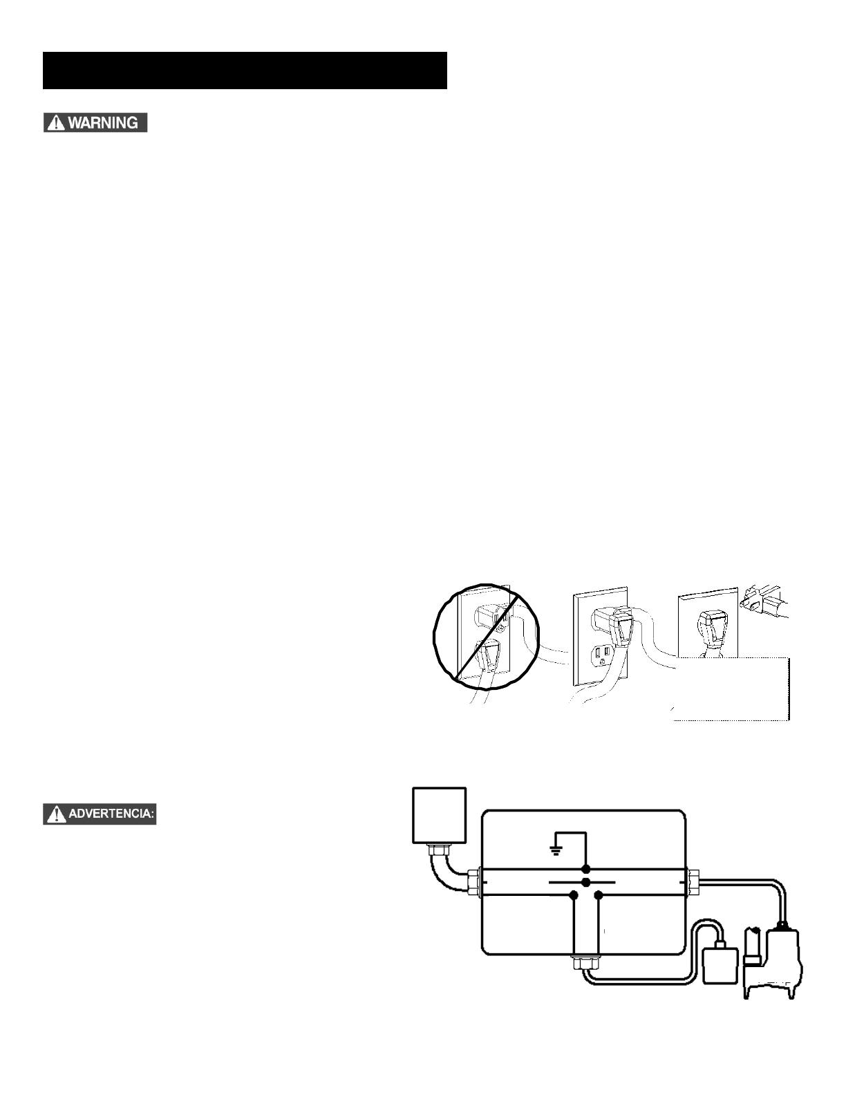
Fig. 5 – Cableado directo de bombas automáticas
monofásicas de 115 V o 208-230 V
Riesgo de descarga eléctrica. Desconecte la bomba de la fuente de alimentación siempre que vaya a manipularla o a realizar
algún ajuste.
Solo personal cualificado deberá encargarse de instalar las conexiones y cables eléctricos necesarios para montar la bomba.
Esta unidad lleva un conector a tierra y un enchufe tomacorriente con conexión a tierra. Para reducir el riesgo de descargas
eléctricas, el conector de puesta a tierra tiene que estar conectado a un panel de control a tierra o si lleva un enchufe a tierra
tendrá que enchufarse a un tomacorriente conectado a tierra.
No derive los cables de puesta a tierra ni retire las espigas a tierra de los enchufes.
No quite el cable ni la protección contra tirones, y no conecte canal para cables a la bomba.
No use cables de extensión.
Con esta bomba, hay que utilizar un circuito derivado independiente conectado a tierra y con fusibles. La fuente de alimentación
tendrá que tener suficiente capacidad para cumplir los requisitos de voltaje y amperaje del motor, indicados en la placa de la bomba.
El tomacorriente o panel deberá encontrarse al alcance del cable de alimentación de la bomba y a 1.22 metros (4 pies) como
mínimo por encima del piso para evitar problemas en caso de inundación.
Se deberá instalar la unidad según las disposiciones del Código eléctrico nacional de Estados Unidos y todos los códigos y
reglamentos locales que correspondan.
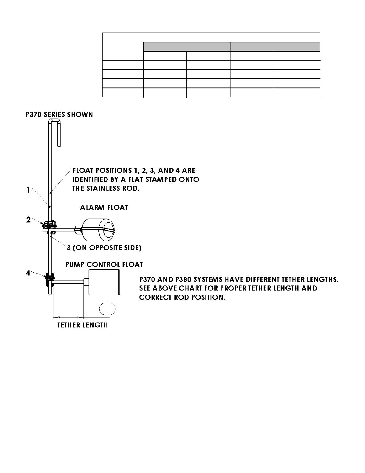
Todos los modelos P370 y de desagüe vertical vienen equipados con un interruptor de flotador montado en el ensamblaje
QuickTree®. Estos modelos vienen con dos cables: uno al interruptor de flotador y el otro al motor. El cable del interruptor lleva un
enchufe en serie, o cascada, en el que se puede enchufar el cable de la bomba (motor) (vea la Figura 4) Esto permite la operación
manual de la bomba.
Si se quiere activar la operación automática se deberán interconectar los dos cables y enchufarse a un tomacorrientes con toma a
tierra y fusibleado independiente y con el amperaje apropiado para su modelo. (Consulte la Sección 1, Información general, o la placa
de la bomba para informarse de las especificaciones eléctricas de su modelo.) Ambos cables llevan enchufes de 3 espigas y se deben
enchufar en un tomacorrientes trifilar con toma a tierra. NO DESMONTE LAS PATAS A TIERRA.
Si se prefiere la operación manual, o falla el interruptor, el
cable de la bomba se puede separar y enchufar en un
tomacorriente, evitando de esta manera el interruptor. Las
bombas monofásicas de 208-230 V se deben operar solamente
sin el interruptor de flotador por medio de un disyuntor o panel de
desconexión. No deje que la bomba funcione en seco por
períodos prolongados.
Si la bomba va a estar cableada directamente a un dispositivo de
control o caja de conexión y es necesario retirar los enchufes, la
labor la deberá llevar a cabo un electricista certificado según el
Código eléctrico nacional de Estados Unidos y los códigos
locales. Vea la Fig. 5 sobre instrucciones acerca de cómo
cablear directamente una bomba automáticamonofásica.
En instalaciones de 208-230 V, uno de
los extremos de la línea que va a la
bomba está siempre activo mientras que
el flotador se encenderá y se apagará.
Instale un desconectador bipolar cerca
de la bomba para no correr riesgos.
5. Servicio eléctrico y operación
FUNCIONAMIENTO
MANUAL
TEMPORAL
¡NO!
¡SÍ!
Fig. 4 Instalación del enchufe en cascada.
Fuente de
alimentación
Tierra
Verde
Verde
Blanco
Blanco
Negro
Negro
Negro
Blanco
Caja de conexión
Bomba
Interruptor
del flotador
  • Page 1 1
  • Page 2 2
  • Page 3 3
  • Page 4 4
  • Page 5 5
  • Page 6 6
  • Page 7 7
  • Page 8 8
  • Page 9 9
  • Page 10 10
  • Page 11 11
  • Page 12 12
  • Page 13 13
  • Page 14 14
  • Page 15 15
  • Page 16 16
  • Page 17 17
  • Page 18 18
  • Page 19 19
  • Page 20 20
  • Page 21 21
  • Page 22 22
  • Page 23 23
  • Page 24 24
  • Page 25 25
  • Page 26 26
  • Page 27 27
  • Page 28 28
  • Page 29 29
  • Page 30 30
  • Page 31 31
  • Page 32 32
  • Page 33 33
  • Page 34 34
  • Page 35 35
  • Page 36 36

Liberty Pumps P382LE41 Guia de usuario

Tipo
Guia de usuario