DeWalt D28700 Manual do usuário
- Categoria
- Ferramentas elétricas
- Tipo
- Manual do usuário
Este manual também é adequado para

D28700
14" (355 mm) Chop Saw
Cortadora/Tronzadora de metales de 14" (355 mm)
Serra de Corte Rápido de 355 mm (14")
INSTRUCTION MANUAL
MANUAL DE INSTRUCCIONES
MANUAL DE INSTRUÇÕES
INSTRUÇÕES DE OPERAÇÃO, CENTRO DE SERVIÇOS E CERTIFICADO
DE GARANTIA. ADVERTÊNCIA: LEIA ESTAS INSTRUÇÕES ANTES DE
UTILIZAR O PRODUTO.
Questions? See us on the World Wide Web at www.dewalt.com
¿Dudas? Visítenos en Internet: www.dewalt.com
Dúvidas? Visite-nos na Internet em www.dewalt.com.br
INSTRUCTIVO DE OPERACIÓN, CENTROS DE SERVICIO Y PÓLIZA DE
GARANTÍA. ADVERTENCIA: LÉASE ESTE INSTRUCTIVO ANTES DE USAR
EL PRODUCTO.

English
11
Important Safety Instructions
WARNING! Read and understand all instructions.
Failure to follow all instructions listed below may result
in electric shock, fire and/or serious personal injury.
SAVE THESE INSTRUCTIONS
• KEEP GUARDS IN PLACE and in working order.
• REMOVE ADJUSTING KEYS AND WRENCHES. Form habit of
checking to see that keys and adjusting wrenches are removed
from tool before turning it on.
• KEEP WORK AREA CLEAN. Cluttered areas and benches
invite injuries.
• DON’T USE IN DANGEROUS ENVIRONMENT. Don’t use
power tools in damp or wet locations, or expose them to rain.
Keep work area well lighted.
• KEEP CHILDREN AWAY. All visitors should be kept at a safe
distance from work area.
• MAKE WORKSHOP KID PROOF with padlocks, master
switches, or by removing starter keys.
• DON’T FORCE TOOL. It will do the job better and safer at the
rate for which it was designed.
• USE RIGHT TOOL. Don’t force tool or attachment to do a job for
which it was not designed.
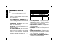
• USE PROPER EXTENSION CORD. Make sure your extension
cord is in good condition. When using and extension cord, be
sure to use one heavy enough to carry the current your product
will draw. An undersized cord will cause a drop in line voltage
resulting in loss of power and overheating. The following table
shows the correct size to use depending on cord length and
nameplate ampere rating. If in doubt, use the next heavier gage.
The smaller the gage number, the heavier the cord.
Voltage (Volts)
Total length of cord in meters (m)
120 - 127V 0 - 7 7 - 15 15 - 30 30 - 50
220 - 240V 0 - 15 15 - 30 30 - 60 60 - 100
Rated Ampere
range
Minimal cross-sectional area of the
cord in meters (mm
2
)
0 - 6A 1.0 1.5 1.5 2.5
6 - 10A 1.0 1.5 2.5 4.0
10 - 12A 1.5 1.5 2.5 4.0
12 - 16A 2.5 4.0 Not Recommended
• WEAR PROPER APPAREL. Do not wear loose clothing,
neckties, rings, bracelets, or other jewelry which may get
caught in moving parts. Nonslip footwear is recommended.
Wear protective hair covering to contain long hair.
Air vents
often cover moving parts and should also be avoided.
• ALWAYS USE SAFETY GLASSES which meet the ANSI Z87.1
requirements. Also use face or dust mask if cutting operation is
dusty. Everyday eyeglasses only have impact resistant lenses,
they are not safety glasses.
• SECURE WORK. Use clamps or a vise to hold work. It’s safer
than using your hand and it frees both hands to operate tool.
• DON’T OVERREACH. Keep proper footing and balance at all
times.
• MAINTAIN TOOLS WITH CARE. Keep tools sharp and clean for
best and safest performance. Follow instructions for lubricating
and changing accessories.
• DISCONNECT TOOLS before servicing; when changing acces-
sories, such as blades, bits, cutters, and the like.
• REDUCE THE RISK OF UNINTENTIONAL STARTING. Make
sure switch is in off position before plugging in.

English
22
• USE RECOMMENDED ACCESSORIES. Consult the instruction
manual for recommended accessories. The use of improper
accessories may cause risk of injury to persons.
• NEVER STAND ON TOOL. Serious injury could occur if the tool
is tipped or if the cutting tool is unintentionally contacted.
• CHECK DAMAGED PARTS. Before further use of the tool,
a guard or other part that is damaged should be carefully
checked to determine that it will operate properly and perform
its intended function — check for alignment of moving parts,
binding of moving parts, breakage of parts, mounting, and any
other conditions that may affect its operation. A guard or other
part that is damaged should be properly repaired or replaced.
• NEVER LEAVE TOOL RUNNING UNATTENDED. TURN
POWER OFF. Don’t leave tool until it comes to a complete stop.
• REPLACEMENT PARTS. When servicing use only identical
replacement parts.
• TO REDUCE THE RISK OF ELECTRIC SHOCK:
a. This equipment may have a polarized plug (one blade is
wider than the other.) This plug will fit in a polarized outlet
only one way. If the plug does not fit, contact a qualified
electrician to install the proper outlet.
b. The tool may be equipped with a 3-prong grounding type
plug. This plug is to be used in a grounded outlet only.
If the plug does not fit, contact a qualified electrician to
install the proper outlet.
c. Do not alter the plug in any way.
Additional Safety Rules for Chop Saws
• Always wear proper eye and respiratory protection.
• Before using, inspect the cutting wheel for cracks or
flaws. If such a crack or flaw is evident, discard the wheel.
The wheel should also be inspected whenever you think
the tool may have been dropped. Flaws may cause wheel
breakage.
• When starting the tool with a new or replacement wheel or
if you are unsure of the condition of the wheel, hold the tool
in a well protected area and let it run for one minute. If the
wheel has an undetected crack or flaw, it should burst in less
than one minute. Never start the tool with a person in line with
the wheel. This includes the operator.
• In operation, avoid bouncing the wheel or giving it rough
treatment. If this occurs, stop the tool and inspect the wheel for
cracks or flaws.
• Clean your chop saw periodically following the procedure in this
manual.
• Do not remove wheel guards or base.
• ALWAYS US E THE VISE OR SPECIAL FIXTURE TO CLAMP
WORK SECURELY. Other aids such as spring, bar, or
C-clamps may be appropriate for certain sizes and shapes of
workpiece. Use care in selecting and placing these clamps and
make a dry run before making a cut.
• Use only 14" type 1 wheels rated at 4100 rpm or higher.
• Allow cut off parts to cool before handling.
• Do not attempt to cut wood or plastic with this tool.
• NEVER CUT MAGNESIUM WITH THIS TOOL.
• Use chop saw in a well-ventilated area.
• Turn chop saw off before removing any pieces from the base.
• DO NOT CUT ELECTRICALLY LIVE MATERIAL.
• Do not use circular saw blades or any other toothed blades
with this tool. Serious injury may result.
• DO NOT OPERATE THIS TOOL NEAR FLAMMABLE
LIQUIDS, GASES OR DUST. Sparks or hot chips from cutting
or arcing motor brushes may ignite com bus tible materials.
• Do not use the side of the abrasive wheel as a deburring grinder.
This will substantially weaken the wheel creating an unsafe
condition. The wheel may come apart.

English
33
CAUTION: Wear appropriate hearing protection during use.
Under some conditions and duration of use, noise from this
product may contribute to hearing loss.
CAUTION: Spark deflector will get hot. Avoid touching or adjusting
while hot. Keep cordset and materials away from spark deflector.
WARNING: Some dust created by power sanding, sawing,
grinding, drilling, and other construction activities contains chemi-
cals known to the State of California to cause cancer, birth defects,
or other reproduc tive harm. Some examples of these chemicals
are:
• lead from lead-based paints,
• crystalline silica from bricks and cement and other masonry
products, and
• arsenic and chromium from chemically-treated lumber
(CCA).
Your risk from these exposures varies, depending on how often you
do this type of work. To reduce your exposure to these chemicals:
work in a well ventilated area, and work with approved safety
equipment, such as those dust masks that are specially designed
to filter out microscopic particles.
• Avoid prolonged contact with dust from power sanding,
sawing, grinding, drilling, and other construction activities.
Wear protective clothing and wash exposed areas with
soap and water. Allowing dust to get into your mouth, eyes, or
lay on the skin may promote absorption of harmful chemicals.
WARNING: Always use NIOSH/OSHA approved respiratory
protection appropriate for the dust exposure. Direct particles away
from face and body.
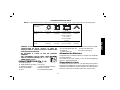
For your convenience and safety, the following warnings are on
your Heavy-Duty 14" (355 mm) Chop Saw:
FOR SAFE OPERATION READ THE INSTRUCTION
MANUAL.
DO NOT USE TOOTHED BLADES.
USE ONLY REINFORCED WHEELS RATED 4100 RPM OR
HIGHER.
WHEN SERVICING USE ONLY IDENTICAL REPLACEMENT
PARTS.
ALWAYS: WEAR EYE PROTECTION, USE GUARDS, CLAMP
WORK IN VISE, USE PROPER RESPIRATORY
PROTECTION.
DO NOT EXPOSE TO RAIN OR USE IN
DAMP LOCATIONS.
ONLY USE CHOP SAW WHEEL OF A MAX.
THICKNESS OF 3.1 mm AND A MAX.
DIAMETER OF 355 mm.
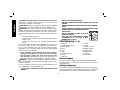
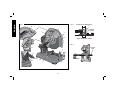
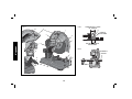
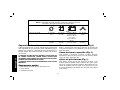
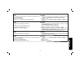
FEATURES (Fig. 1, 4)
A. Lock pin J. Wheel
B. Spark deflector screw K. Guard
C. Spark deflector L. Wheel lock lever
D. Base M. Depth stop bolt
E. Fence N. Trigger switch
F. Vise O. Padlock hole
G. 8 mm hex wrench P. Jam nut
H. Crank Q. Fence bolts
I. Vise lever
Power Supply
Be sure your power supply agrees with the nameplate marking.
A voltage decrease of more than 10% will cause a loss of power
and overheating.
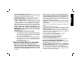
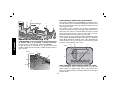
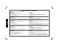
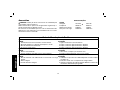
Cutting Capacity
The wide vise opening and high pivot point provide cutting capacity
for many large pieces. Use the cutting capacity chart to determine
total maximum size of cuts that can be made with a new wheel.

English
44
CAUTION: CERTAIN LARGE, CIRCULAR OR IRREGULARLY
SHAPED OBJECTS MAY REQUIRE ADDITIONAL HOLDING
MEANS IF THEY CANNOT BE HELD SECURELY IN VISE.
CAUTION: DO NOT CUT MAGNESIUM WITH THIS TOOL.
Standard Equipment
1 14" (455 mm) Metal Cutting Abrasive Wheel
1 Wheel Wrench
1 Instruction manual
To Carry (Fig. 1)
Fold down unit to position where you can carry the saw. Push in
lock pin (A) to lock arm down.
Unlocking (Fig. 1)
To unlock tool and raise head, depress motor arm slightly and pull
lock pin (A) out. Motor arm will then pivot upward.
Workpiece Shape:
A x B
90º Cutting Angle A = 4.5" A = 4-11/16" 4-1/2" x 5-1/8" A = 5-3/8"
(115 mm) (115 mm) (119 mm x 130 mm) (137 mm)
4" x 7-5/8"
(102 mm x 194 mm)
3" x 9"
(76 mm x 229 mm)
45º Cutting A = 3-13/16" A = 3-13/16" 4-1/2" x 3-13/16" A = 3-13/16"
Angle (98 mm) (98 mm) (115 mm x 98 mm) (98 mm)
Spark Deflector Adjustment (Fig. 1)
To best deflect sparks away from surrounding persons and
materials, loosen the screw (B), adjust the spark deflector (C)
and then retighten screw. Do not allow cordset to come into
contact with deflector or sparks as damage to cordset may occur.
Depth Stop (Fig. 1)
Depth stop is set at the factory for a new 14" (455 mm) wheel to
prevent wheel from cutting into the supporting surface. To allow
more depth of cut, use the 8 mm hex wrench provided (G) to
loosen the depth stop bolt (M) and raise bolt to desired height and
then turn jam nut (P) clockwise until seated firmly on the casting.
Securely tighten the depth stop bolt before use.
CAUTION: When changing to a new wheel, readjust depth stop
to original position to prevent cutting into supporting surface.
MAXIMUM CUTTING CAPACITY
NOTE: Capacity shown on chart assumes no wheel wear and optimum fence position.

English
55
F
DIAMETER OF WORKPIECE
E
SPACER
BLOCK
WIDTH OF SPACER BLOCK
FIG. 2
BLOCK
FIG. 3
CUT-OFF
END
FIG. 1
A
M
E
I
H
K
J
F
C
L
D
G
N
O
P
B
C

English
6
Trigger Switch (Fig. 1)
To start the tool, depress the trigger switch (N). To turn the tool off,
release the trigger switch. Keep hands and material from wheel until
it has coasted to a stop.
To prevent unauthorized use of tool, install a standard padlock (not
included) into the padlock hole (O) located in the trigger.
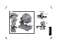
Material Clamping and Supporting
• Angles are best clamped and cut with both legs resting against
base.
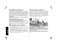
• A spacer block slightly narrower than the workpiece can be
used to increase wheel utilization (Fig. 2).
• Long workpieces must be supported by a block so it will be
level with top of base (Fig. 3). The cut off end should be free to
fall downward to avoid wheel binding.
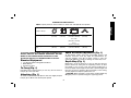
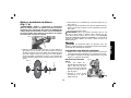
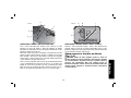
Vise Operation (Fig. 4)
The vise (F) has a quick-travel feature. To release the vise when it
is clamped tightly, turn the crank (H) counterclockwise one or two
times to remove clamping pressure. Lift vise lever (I) up. Pull crank
assembly out as far as desired. Vise may be pushed forward into
work without cranking. Lower vise lever (I) then tighten vise (F) on
work by using crank (H).
F
E
Q
FORWARD
FIG. 4
I
H
6
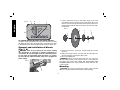
Fence Operation (Fig. 5, 6)
WARNING: Turn off and unplug the tool before making any
adjustments or removing or installing attachments or
accessories. Be sure the trigger switch is in the OFF position.
The fence (E) can be adjusted two ways: to change desired cutting
angle and to change spacing between the fence and vise.
FIG. 5
Q
E
G
F
R
TO CHANGE THE DESIRED CUTTING ANGLE
Use the wrench provided to loosen (do not remove) the two fence
bolts (Q). Align the desired angle indicator line with the slot line (R)
in the base (D). Securely tighten both fence bolts before use.
For more accurate square cuts, disconnect the power supply,
loosen the two fence bolts, push arm down until wheel extends into
base. Place a square against the wheel and adjust fence against
the square. Securely tighten both fence bolts before use.
When making a miter cut, the vise (F) may not clamp securely,
depending on the thickness of the workpiece and the miter angle.
Other aids (such as spring, bar or C-clamps) will be necessary to
secure the workpiece to the fence when making these cuts.

English
77
J
FIG. 6
E
Q
R
TO CHANGE SPACING BETWEEN THE FENCE AND VISE
Using the wrench provided, loosen and remove the two fence bolts
(Q). Adjust the fence (E) to desired locations. Insert both fence bolts
in provided locations. Securely tighten both fence bolts before use.
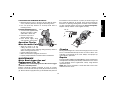
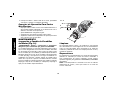
Removal and Installation of Wheels
(Fig. 7, 8)
WARNING: Turn off and unplug the tool before making
any adjustments or removing or installing attachments or
accessories. Be sure the trigger switch is in the OFF position.
Do not make any adjustment while the wheel is in motion.
Do not make any adjustment while chop saw is plugged into
power supply.
L
FIG. 7
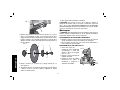
1. Push in wheel lock lever (L) and rotate wheel (J) by hand
until wheel lock lever engages slot in inside flange (S) to lock
wheel. Loosen the bolt (T) counterclockwise in the center of the
abrasive wheel with the 8 mm hex wrench (G). Bolt has right-
hand thread.
S
U
V
J
FIG. 8
T
2. Remove the bolt (T), washer (U), outside flange (V) and old
wheel (J).
3. Make sure flange surfaces are clean and flat. Install the new
abrasive wheel by reversing the above steps.
4. Do not overtighten bolt.
WARNING: Check the work surface that the chop saw rests
on when replacing with a new abrasive wheel. It is possible that
the wheel may contact ANY ITEMS OR STRUCTURE THAT
EXTENDS ABOVE work surface (under the base) when the arm
is fully lowered.
Mounting
CAUTION: Tool must be supported on stable, level, non-skid
surface to prevent unexpected movement when operating.

English
88
PROCEDURE FOR PERMANENT MOUNTING
1. Mark through the holes in the base (D) and drill two holes,
5/16" (7.94 mm) diameter, through the mounting surface.
2. Use 1/4" (6.35 mm) fasteners to securely mount base to
mounting surface.
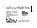
CRADLE MOUNTING (FIG. 9)
1. Cut two boards approximately
FIG. 9
20" long x 2" high x 4" wide
(508 x 50.8 x 101.6 mm).
2. Place the chop saw at
desired work location.
3. Place boards tightly along
side and nail to work surface.
Operation Tips for
More Accurate Cuts
• Allow the wheel to do the
cutting. Excessive force will
cause the wheel to glaze reducing cutting efficiency and/or to
deflect causing inaccurate cuts.
• Properly adjust fence angle.
• Make sure material is laying flat across base.
• Properly clamp material to avoid movement and vibration.
MAINTENANCE
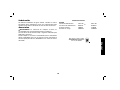
Motor Brush Inspection and
Replacement (Fig. 10)
WARNING: Turn off and unplug the tool. Be sure the trigger
switch is in the OFF position.
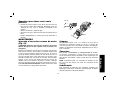
Brushes should be regularly inspected for wear. To inspect
brushes, unscrew the two end cap screws (W) and remove end cap
(X). Remove brush cap (Z). Brushes (Y) should slide freely in brush
box. If brushes are worn down to .3" (8 mm) as shown in Figure 10
they should be replaced. To reinstall, push new brush back into
brush box. If replacing existing brush, maintain same orientation
as when removed. Replace the brush cap (do not overtighten).
Replace end cap and two screws. Tighten securely.
.3"
(8 mm)
FIG. 10
Z
W
Y
X
Y
Cleaning
Blowing dust and grit out of the main housing by means of an air
hose is recommended and may be done as often as dirt is seen
collecting in and around the air vents. Always wear proper eye
and respiratory protection.
Repairs
To assure product SAFETY and RELIABILITY, repairs, maintenance
and adjustment should be performed by authorized service centers
or other qualified service organizations, always using identical
replacement parts.
NOTE: Unit may be converted to a 3-wire twist lock cord set at an
authorized service center.

English
99
Lubrication
Closed-type, grease-sealed ball bearings are used throughout.
These bearings have sufficient lubrication packed in them at the
factory to last the life of the chop saw.
Accessories
WARNING: The use of any other accessory not recommended
for use with this tool could be hazardous.
Use only high-strength Type 1 organic bonded wheels rated
4100 rpm or higher.
Recommended accessories for use with your tool are available at
extra cost from your local dealer or authorized service center.
Troubleshooting Guide
TROUBLE! TOOL WILL NOT START
WHAT’S WRONG? WHAT TO DO…
1. Tool not plugged in. 1. Plug in saw.
2. Fuse blown or circuit breaker tripped. 2. Replace fuse or reset circuit breaker.
3. Cord damaged. 3. Have cord replaced by authorized service center.
4. Brushes worn out. 4. Replace brushes.
TROUBLE! TOOL MAKES UNSATISFACTORY CUTS
WHAT’S WRONG? WHAT TO DO…
1. Glazed wheel. 1. Dress the wheel or replace with a new one.
2. Workpiece incorrectly placed or clamped. 2. Firmly clamp and support workpiece.
TROUBLE! BLADE DOES NOT COME UP TO SPEED
WHAT’S WRONG? WHAT TO DO…
1. Extension cord too light or too long. 1. Replace with adequate size cord. See chart on page 1.
2. Low voltage. 2. Contact your electric company.
3. Low generator voltage. 3. Check generator output voltage. Reduce number of tools powered
by the generator.

English
1010
Troubleshooting Guide…
TROUBLE! TOOL VIBRATES EXCESSIVELY DURING CUT
WHAT’S WRONG? WHAT TO DO…
1. Tool not mounted securely to stand or work bench. 1. Tighten all mounting hardware. See page 8, Procedure for
Permanent Mounting.
2. Damaged wheel. 2. Replace wheel.
3. Workpiece not clamped properly. 3. Refer to Material Clamping and Supporting page 6.
TROUBLE! DOES NOT MAKE ACCURATE CUTS
WHAT’S WRONG? WHAT TO DO…
1. Fence not adjusted correctly. 1. Check and adjust. See Fence Operation on page 6.
2. Wheel is not square to fence. 2. Check and adjust.
3. Excessive force used to make cut. 3. Reduce cutting force, let the wheel do the work.
4. Work piece moving. 4. Clamp workpiece securely. See Material Clamping and
Supporting, page 6. Make sure material is laying flat against the
base.
TROUBLE! CANNOT MOVE ARM
WHAT’S WRONG? WHAT TO DO…
1. Lock down pin is engaged. 1. Push down slightly on the arm, pull down lock down pin and
raise arm.
TROUBLE! MATERIAL MOVES DURING CUT
WHAT’S WRONG? WHAT TO DO…
1. Fence slipping or workpiece incorrectly placed or clamped. 1. See Material Clamping and Supporting, page 6.
2. Vise too loose 2. Tighten vise clamping.
3. Excessive cutting force. 3. Reduce cutting force.

Español
1111
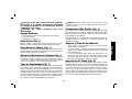
Instrucciones de seguridad
importantes
¡ADVERTENCIA! Lea todas las instrucciones hasta
comprenderlas. El incumplimiento con alguna de las
instrucciones enumeradas más abajo puede resultar en descarga
eléctrica, incendio y/o lesiones corporales serias.
CONSERVE ESTAS INSTRUCCIONES
• MANTENGA LOS PROTECTORES EN SU SITIO y en buenas
condiciones de funcionamiento.
• QUITE LAS LLAVES DE AJUSTE. Hágase el hábito de
comprobar que la herramienta no tenga ninguna llave de ajuste
puesta antes de encenderla.
• MANTENGA LIMPIA EL ÁREA DE TRABAJO. Las áreas
y mesas de trabajo desordenadas aumentan el riesgo de
lesiones.
• NO UTILICE LA HERRAMIENTA EN AMBIENTES
PELIGROSOS. No utilice máquinas herramienta en lugares
húmedos o mojados ni las exponga a lluvia. Mantenga el área
de trabajo bien iluminada.
• MANTENGA ALEJADOS A NIÑOS. Toda visita debería
mantenerse a una distancia segura del área de trabajo.
• QUE SU TALLER SEA A PRUEBA DE NIÑOS. Para ello
utilice candados o conmutadores maestros o quite las llaves de
arranque.
• NO FUERCE LA HERRAMIENTA. La herramienta hace el
trabajo mejor y más seguro a la velocidad para la cual fue
diseñada.
• UTILICE LA HERRAMIENTA CORRECTA. No fuerce la
herramienta o el accesorio a que realice una tarea para la cual
no fue diseñada.
• USE EL ALARGADOR INDICADO. Cerciórese de que
su alargador esté en buenas condiciones. Cuando use un
alargador, asegúrese de que sea lo bastante resistente como
para llevar la corriente que su producto requerirá. Un alargador
de menor calibre causará una caída en el voltaje de la línea
lo que resultará en pérdida de potencia y sobrecalentamiento.
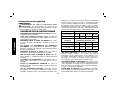
El siguiente cuadro muestra el tamaño correcto a utilizar,
dependiendo del largo del cable y del amperaje nominal. En
caso de tener dudas, utilice el de mayor calibre. Mientras menor
sea el número del calibre, mayor la capacidad del cable.
Ténsion (Volts) Longitud del cable in metros (m)
120 - 127V 0 - 7 7 - 15 15 - 30 30 - 50
220 - 240V 0 - 15 15 - 30 30 - 60 60 - 100
Corriente nominal
(Ampéres)
Sección nominal mínima del cable
in milímetros quadrados (mm
2
)
0 - 6A 1.0 1.5 1.5 2.5
6 - 10A 1.0 1.5 2.5 4.0
10 - 12A 1.5 1.5 2.5 4.0
12 - 16A 2.5 4.0 No recomendado
• USE ROPA ADECUADA. No lleve ropa suelta, guantes,
corbatas, anillos, pulseras u otras joyas que podrían
engancharse en las piezas móviles. Se recomienda el uso
de calzado antideslizante. Cúbrase y recójase el pelo si lo
tiene largo. Los orificios de ventilación suelen cubrir piezas
en movimiento, por lo que también se deben evitar.
• USE SIEMPRE GAFAS DE SEGURIDAD que cumplan con los
requisitos de ANSI Z87.1. Utilice además una máscara para la
cara o guardapolvo si la operación de corte genera demasiado
polvo. Los anteojos de uso diario sólo tienen lentes resistentes
a golpes, no son gafas de seguridad.
• AFIRME BIEN SU TRABAJO. Utilice abrazaderas o tornillos
para sujetar las piezas en las que trabaja. Es más seguro, y así
podrá utilizar ambas manos para operar la herramienta.

Español
1212
• NO SE SOBREEXTIENDA. Manténgase siempre bien apoyado
y equilibrado.
• CUIDE LAS HERRAMIENTAS. Mantenga las herramientas
afiladas y limpias para un funcionamiento mejor y más seguro.
Siga las instrucciones para lubricar y cambiar accesorios.
• DESENCHUFE LAS HERRAMIENTAS antes de reparar o
mantenerlas; cuando cambie accesorios tales como hojas,
brocas, mecanismos de corte y otros por el estilo.
• REDUZCA EL RIESGO DE PUESTAS EN MARCHA
ACCIDENTALES. Asegúrese de que el conmutador esté
apagado antes de enchufarla.
• UTILICE LOS ACCESORIOS RECOMENDADOS. Consulte
el manual de instrucciones para conocer los accesorios
recomendados. El uso de accesorios no debidos puede
producir un riesgo de lesiones corporales.
• NUNCA SE PARE SOBRE LA HERRAMIENTA. Podría sufrir
graves lesiones si la herramienta se cae a un lado o si se entra
en contacto no intencionado con la herramienta de corte.
• REVISE LAS PIEZAS DAÑADAS. Antes de continuar usando
la herramienta, se debe revisar cuidadosamente el protector o
cualquier otra pieza dañada para determinar que funcionará
correctamente y realizará la función para la que fue diseñada -
verifique que las piezas móviles estén alineadas, que no estén
atascadas, rotas, montadas una sobre otra o de otra forma
que pudiera afectar su operación. Cualquier protector o pieza
dañada debe repararse debidamente o cambiarse.
• JAMÁS DEJE SIN SUPERVISIÓN UNA HERRAMIENTA EN
FUNCIONAMIENTO. APAGUE LA HERRAMIENTA. No deje la
herramienta hasta que no se haya detenido completamente.
• REPUESTOS. Cuando realice mantenimiento, use sólo
repuestos originales.
• PARA REDUCIR EL RIESGO DE DESCARGA ELÉCTRICA:
a. Puede que este equipo tenga un enchufe polarizado (con
una para más ancha que la otra.) Este enchufe sólo puede
ser insertado en una toma de corriente polarizada de
una manera. Si el enchufe no entra, comuníquese con un
electricista calificado para que instale la toma de corriente
apropiada.
b. Puede que la herramienta venga equipada con un enchufe
con conexión a tierra de tres patas. Este enchufe sólo puede
ser utilizado en una toma de corriente con conexión a tierra.
Si el enchufe no entra, comuníquese con un electricista
calificado para que instale la toma de corriente apropiada.
c. No altere el enchufe de ninguna forma.
Reglas de seguridad adicionales para
tronzadoras de metal
• Use siempre protección ocular y respiratoria apropiada.
• Antes de usarla, revise el disco de corte para verificar que
no esté trizado o tenga fallas. Si tuviera alguna trizadura o
falla, descarte el disco. También se debe inspeccionar el
disco siempre que piense que la herramienta pudiera haber
caído. Las fallas pueden provocar la rotura del disco.
• Cuando arranque la herramienta con un disco nuevo o de
repuesto o si no está seguro de la condición del disco,
sostenga la herramienta en un lugar bien protegido y
déjela andar por un minuto. Si el disco tiene una trizadura
o falla que haya pasado inadvertida, se debería romper
en pedazos en menos de un minuto. Nunca encienda la
herramienta cuando haya una persona alineada con el disco.
Esto incluye al operador.
• Durante la operación, evite hacer rebotar el disco o tratarlo
bruscamente. Si ello sucediera, detenga la herramienta y
revise que el disco no tenga trizaduras o fallas.
• Limpie su sierra circular estacionaria periódicamente, siguiendo
el procedimiento de este manual.
• No quite los protectores del disco o la base.
• SIEMPRE USE EL TORNO O DISPOSITIVO DE FIJACIÓN
ESPECIAL PARA SOSTENER BIEN LA PIEZA DE TRABAJO.

Español
1313
Otros dispositivos tales como abrazaderas de resorte, de barra
o en C pueden ser apropiadas para piezas de trabajo de
diferentes tamaños y formas. Tenga cuidado al seleccionar y
colocar estas abrazaderas y haga un movimiento de práctica
antes de hacer un corte.
• Use sólo discos tipo 1 de 355 mm (14 pulg.) para 4100 rpm o
superiores.
• Deje que las piezas cortadas se enfríen antes de cogerlas.
• No intente cortar madera o plástico con esta herramienta.
• NUNCA CORTE MAGNESIO CON ESTA HERRAMIENTA.
• Use la sierra circular estacionaria en un lugar bien ventilado.
• Apague la sierra circular estacionaria antes de quitar cualquier
pieza de su base.
• NO CORTE MATERIALES CARGADOS DE ELECTRICIDAD.
• No use hojas para sierras circulares ni ninguna otra hoja
dentada con esta herramienta. Pueden producirse lesiones
graves.
• NO OPERE ESTA HERRAMIENTA CERCA DE LÍQUIDOS,
GASES O POLVOS INFLAMABLES. Las chispas o partículas
calientes generadas del corte o las escobillas del motor podrían
encender materiales combustibles.
• No use el lado del disco abrasivo como pulidor de rebabas. Esto
debilitará significativamente el disco y creará una condición
poco segura. El disco podría desarmarse.
ATENCIÓN: Use protección auditiva apropiada durante
el uso de esta herramienta. Bajo algunas condiciones y
duraciones de uso, el ruido producido por este producto puede
contribuir a la pérdida auditiva.
ATENCIÓN: El deflector de chispas se calienta. Evite tocarlo
o ajustarlo mientras está caliente. Mantenga cables y materiales
alejados del deflector de chispas.
ADVERTENCIA: Algunos tipos de polvo, como aquellos
generados por el lijado, serruchado, pulido y taladrado eléctrico
y otras actividades de construcción, contienen químicos que el
estado de California sabe causan cáncer, defectos de nacimiento
y otros daños reproductivos. Algunos ejemplos de estos químicos
son:
• plomo procedente de pinturas con base de plomo,
• óxido de silicio procedente de ladrillos, cemento y otros
productos de mampostería, y
• arsénico y cromo provenientes de maderas tratadas con
químicos (arseniato de cobre cromado).
El peligro derivado de la exposición a estos materiales varía en
función de la frecuencia con que se realice este tipo de trabajo.
Para reducir su exposición a estos químicos: trabaje en una
zona bien ventilada y llevando equipos de seguridad aprobados,
como mascarillas antipolvo especialmente diseñadas para filtrar
partículas microscópicas.
• Evite el contacto prolongado con polvo generado por el
lijado, serruchado, pulido y taladrado eléctricos y otras
actividades de construcción. Vista ropa protectora y lave las
áreas de la piel expuestas con agua y jabón. Si permite que el
polvo se introduzca en su boca o sus ojos, o que quede sobre la
piel, puede favorecer la absorción de químicos peligrosos.
ADVERTENCIA: Siempre use protección respiratoria aprobada
por NIOSH (Instituto Nacional de Seguridad y Salud en el Trabajo)
u OSHA (Administración de Seguridad y Salud en el Trabajo)
apropiada para la exposición al polvo. Dirija las partículas en
dirección contraria a la cara y el cuerpo.
Para su conveniencia y seguridad, su tronzadora de metales de
14 pulg. (355 mm) tiene las siguientes advertencias:
PARA OPERARLA DE UNA MANERA SEGURA, LEA EL
MANUAL DE INSTRUCCIONES.
NO UTILICE HOJAS DENTADAS.
UTILICE SÓLO DISCOS REFORZADOS CALIFICADOS
PARA 4100 RPM O SUPERIORES.
CUANDO REALICE MANTENIMIENTO, USE SÓLO
REPUESTOS ORIGINALES.

Español
14
Forma de la pieza
de trabajo:
A x B
Ángulo de corte A = 115 mm A = 4-11/16" 115 mm x 130 mm A = 137 mm
de 90º (4,5") (119 mm) (4-1/2" x 5-1/8") (5-3/8")
102 mm x 194 mm
(4" x 7-5/8")
76 mm x 229 mm
(3" x 9")
Ángulo de corte A = 98 mm A = 98 mm 115 mm x 98 mm A = 98 mm
de 45º (3-13/16") (3-13/16") (4-1/2” x 3-13/16") (3-13/16")
SIEMPRE: UTILICE PROTECCIÓN OCULAR; USE LOS
PROTECTORES DE HOJA; SUJETE LA PIEZA DE
TRABAJO CON EL TORNO; UTILICE LA PROTECCIÓN
RESPIRATORIA APROPIADA.
NO EXPONGA A LLUVIA NI USE EN LUGARES
HÚMEDOS.
USE ÚNICAMENTE DISCOS PARA CORTE
CON UN ESPESOR MÁXIMO DE 3.1 mm Y
DIÁMETRO DE 355 mm.
CARACTERÍSTICAS (Fig. 1, 4)
A. Clavija de fijación J. Disco
B. Tornillo deflector de chispas K. Protector
C. Deflector de chispas L. Palanca de fijación del disco
D. Base profundidad M. Perno de tope de
E. Guía N. Conmutador tipo gatillo
F. Torno O. Orificio para insertar candado
G. Llave hexagonal de 8 mm P. Tuerca de obstrucción
H. Manivela Q. Pernos para la guía
I. Palanca del torno
Alimentación Eléctrica
Compruebe que su suministro eléctrico concuerde con el indicado
en la placa nominal.
Una reducción de voltaje superior al 10% provocará pérdida de
potencia y sobrecalentamiento.
Capacidad de Corte
La amplitud de apertura del torno y la altura del punto de pivote
proporcionan capacidad de corte para varias piezas grandes. Use
la tabla de capacidad de corte para determinar el tamaño máximo
total de los cortes que se pueden realizar con un disco nuevo.
CAPACIDAD MÁXIMA DE CORTE
NOTA: La capacidad indicada en la tabla supone que el disco no está desgastado y que la guía está en la posición óptima.

Español
1515
F
DIÁMETRO DE LA PIEZA
DE TRABAJO
E
BLOQUE
ESPACIADOR
ANCHO DEL BLOQUE
ESPACIADOR
FIG. 2
BLOQUE
FIG. 3
EXTREMO A
CORTAR
FIG. 1
A
M
E
I
H
K
J
F
C
L
D
G
N
O
P
B
C

Español
1616
ATENCIÓN: Cuando cambie el disco por uno nuevo, vuelva
a ajustar el tope a la posición original para evitar que corte la
superficie de apoyo.
Conmutador Tipo Gatillo (Fig. 1)
Para arrancar la herramienta, presione el conmutador tipo gatillo
(N). Para apagar la herramienta, suelte el conmutador tipo gatillo.
Mantenga las manos y el material alejados del disco hasta que se
haya detenido completamente.
Para prevenir el uso no autorizado de la herramienta, instale un
candado estándar (no incluido) en el orificio para candados (O)
ubicado en el gatillo.
Soporte y Fijación del Material
• Podrá sujetar y cortar ángulos mejor con ambas piernas
descansando contra la base.
• Se puede utilizar un bloque espaciador ligeramente más
angosto que la pieza de trabajo para aumentar la utilización
de la rueda (Fig. 2).
• Las piezas de trabajo largas deben ser soportadas por un
bloque para que estén al mismo nivel que la parte superior
de la base (Fig. 3). El extremo a cortar debería poder caer
libremente para evitar que el disco se atasque.
Operación del Torno (Fig. 4)
El torno (F) tiene una característica que permite soltarlo
rápidamente. Para soltar el torno cuando está bien ajustado, gire
la manivela (H) en dirección contraria a las manillas del reloj una
o dos veces para liberar la presión de ajuste. Levante la palanca
del torno (I). Tire de la unidad de la manivela lo más que desee.
El torno puede ser empujado hacia la pieza de trabajo sin tener
que girar la manivela. Baje la palanca del torno (I) y luego ajuste el
torno (F) en la pieza de trabajo, girando la manivela (H).
ATENCIÓN: PUEDE QUE CIERTOS OBJETOS GRANDES,
CIRCULARES O DE FORMAS IRREGULARES REQUIERAN
DE SOPORTE ADICIONAL SI NO PUEDEN SER SUJETOS
FIRMEMENTE EN EL TORNO.
ATENCIÓN: NO CORTE MAGNESIO CON ESTA
HERRAMIENTA.
Equipo Estándar
1 disco abrasivo de 355 mm (14 pulg.) para cortar metales
1 Llave para el disco
1 Manual de instrucciones
Para Portar (Fig. 1)
Doble la unidad a una posición que le permita portar la sierra.
Empuje la clavija de fijación (A) para fijar el brazo hacia abajo.
Para Quitar el Seguro (Fig. 1)
Para quitar el seguro y elevar la cabeza de la herramienta, presione
el brazo del motor ligeramente y tire de la clavija de fijación (A) para
quitarla. El brazo del motor se levantará.
Ajuste del Deflector de Chispas (Fig. 1)
Para deflectar mejor las chispas de las personas y los materiales
circundantes, afloje el tornillo (B), ajuste el deflector de chispas
(C) y vuelva a ajustar el tornillo. No permita que el cable entre en
contacto con el deflector o las chispas para evitarle daños.
Tope de Profundidad (Fig. 1)
El tope de profundidad viene fijado de fábrica para un disco de 355
mm (14 pulg.) nuevo, para evitar que el disco corte la superficie de
apoyo. Para permitir una mayor profundidad de corte, use la llave
hexagonal de 8 mm incluida (G) para aflojar el perno de tope de
profundidad (M). Luego eleve el perno a la altura deseada y gire
la tuerca de obstrucción (P) en dirección de las manillas del reloj
hasta que queden firmemente asentadas sobre la moldura. Ajuste
bien el perno de tope de profundidad antes de usarlo.

Español
1717
PARA CAMBIAR EL ÁNGULO DE CORTE DESEADO
Use la llave incluida para aflojar (sin quitar) los dos pernos de la
guía (Q). Alinee la línea de indicación del ángulo deseado con la
línea de la ranura (R) en la base (D). Ajuste bien ambos pernos de
la guía antes de usarla.
Para realizar cortes cuadrados más precisos, desenchufe la
herramienta, afloja los dos pernos de la guía, empuje el brazo hacia
abajo hasta que el disco se extienda dentro de la base. Coloque
una escuadra contra el disco y ajuste la guía contra la escuadra.
Ajuste bien ambos pernos de la guía antes de usarla.
Puede que el torno (F) no sujete bien la pieza de trabajo al realizar
cortes a inglete, dependiendo del grosor de la pieza y el ángulo de
inglete. Otros dispositivos auxiliares (tales como abrazaderas de
resorte, de barra o en C) serán entonces necesarios para sujetar
la pieza a la guía al realizar estos cortes.
J
FIG. 6
E
Q
R
PARA CAMBIAR EL ESPACIO ENTRE LA GUÍA Y EL TORNO
Con la llave incluida, afloje y retire ambos pernos de la guía (Q).
Ajuste la guía (L) al lugar deseado. Inserte ambos pernos de la
guía en los lugares previstos. Ajuste bien ambos pernos de la guía
antes de usarla.
F
E
Q
HACIA ADELANTE
FIG. 4
I
H
Operación de la Guía (Fig. 5, 6)
ADVERTENCIA: Apague y desenchufe la herramienta antes
de realizar ajustes o de quitarle o ponerle accesorios.
Asegúrese que el conmutador tipo gatillo esté APAGADO.
La guía (E) puede ser ajustada en una de dos formas: para
cambiar el ángulo de corte deseado y cambiar el espacio entre la
guía y el torno.
FIG. 5
Q
E
F
R
G

Español
1818
FIG. 9
2. Retire el perno (T), la arandela (U), la pestaña exterior (V) y el
disco viejo (J).
3. Asegúrese que las superficies de la pestaña queden limpias y
planas. Instale el disco abrasivo nuevo invirtiendo los pasos de
más arriba.
4. No ajuste demasiado el perno.
ADVERTENCIA: Revise la superficie de trabajo sobre la cual
descansa la sierra cuando le cambie el disco abrasivo por uno
nuevo. Es posible que el disco entre en contacto con CUALQUIER
COSA O ESTRUCTURA QUE SE EXTIENDA por encima de la
superficie de trabajo (debajo de la base) cuando el brazo está
totalmente abajo.
Montaje
ATENCIÓN: La herramienta debe ser apoyada sobre una
superficie estable, nivelada y no deslizante para evitar el movimiento
inesperado de esta durante la operación.
PROCEDIMIENTO PARA MONTAJE PERMANENTE
1. Marque por los orificios de la base (D) y perfore dos orificios de
7,94 mm (5/16 pulg.) de diámetro en la superficie de montaje.
2. Use fijadores de 6,35 mm (1/4 pulg.) para fijar la base en forma
segura a la superficie de montaje.
MONTAJE CON SOPORTES
(FIG. 9)
1. Corte dos tablas de
FIG. 9
aproximadamente 508 mm de
largo x 50,8 mm de alto x
101,6 mm de ancho (20 pulg.
de largo x 2 pulg. de alto x 4
pulg. de ancho).
2. Coloque la sierra circular
estacionaria en el lugar de
trabajo deseado.
Retiro e Instalación de Discos
(Fig. 7, 8)
ADVERTENCIA: Apague y desenchufe la herramienta
antes de realizar ajustes o de quitarle o ponerle accesorios.
Asegúrese que el conmutador tipo gatillo esté APAGADO. No
realice ningún ajuste mientras el disco esté en movimiento.
No realice ningún ajuste mientras la tronzadora de metales
esté enchufada a la toma de corriente.
FIG. 7
L
1. Empuje la palanca de fijación del disco (L) hacia adentro y
gire el disco (J) con la mano hasta que la palanca de fijación
del disco enganche en la ranura dentro de la pestaña (S) para
fijar el disco. Afloje el perno (T) que está en el centro del disco
abrasivo girándolo en dirección contraria a las manillas del
reloj con la llave hexagonal de 8 mm (G). El perno tiene un hilo
diestro.
S
U
V
J
FIG. 8
T

Español
1919
Z
FIG. 10
Y
W
X
8 mm
(.3")
Y
Limpieza
Se recomienda limpiar el polvo y la arenilla de la caja principal
de la herramienta con una manguera de aire, tan frecuentemente
como sea necesario limpiar tierra acumulada en las rejillas de
ventilación y alrededor de estas. Use siempre protección ocular y
respiratoria apropiada.
Reparaciones
Las reparaciones, el mantenimiento y los ajustes de este producto
deberían ser realizados por centros de servicio autorizados u
otras organizaciones de servicio calificadas, usando siempre
repuestos originales, para garantizar la SEGURIDAD y FIABILIDAD
del producto.
NOTA: La unidad puede ser convertida a una con un cable de
alimentación de 3 hilos y cierre por torsión en un centro de
servicio autorizado.
3. Coloque las tablas a ambos lados de la sierra, ajustándola
entre ellas, y clávelas a la superficie de trabajo.
Consejos de Operación Para Cortes
Más Precisos
• Deje que el disco realice el corte. Si usa demasiada fuerza, el
disco podría resbalar, reduciendo así su eficiencia de corte o
deflectar, causando cortes imprecisos.
• Ajuste debidamente el ángulo de la guía.
• Asegúrese que el material esté plano contra la base.
• Sujete bien el material con dispositivos de sujeción para evitar
que se mueva y que la sierra vibre.
MANTENIMIENTO
Inspección y Cambio de Escobillas
del Motor (Fig. 10)
ADVERTENCIA: Apague y desenchufe la herramienta.
Asegúrese que el conmutador tipo gatillo esté APAGADO.
Las escobillas deberían ser revisadas regularmente para verificar
que no estén desgastadas. Para revisar las escobillas, destornille
los dos tornillos de la tapa (W) y retire la tapa (X). Retire la tapa
de las escobillas (Z). Las escobillas (Y) deberían poder deslizarse
libremente dentro de la caja. Si las escobillas están desgastadas
a 8 mm (0,3 pulg.), como aparece en la Figura 10, deberían ser
cambiadas. Para volverlas a instalar, empuje la escobilla nueva
dentro de la caja. Si va a reponer la escobilla existente, recuerde
poner la escobilla en la misma orientación que cuando fue retirada.
Reponga la tapa de las escobillas (no sobreajuste). Reponga la
tapa y los dos tornillos. Ajuste firmemente.
A página está carregando...
A página está carregando...
A página está carregando...
A página está carregando...
A página está carregando...
A página está carregando...
A página está carregando...
A página está carregando...
A página está carregando...
A página está carregando...
A página está carregando...
A página está carregando...
A página está carregando...
A página está carregando...
A página está carregando...
A página está carregando...
-
 1
1
-
 2
2
-
 3
3
-
 4
4
-
 5
5
-
 6
6
-
 7
7
-
 8
8
-
 9
9
-
 10
10
-
 11
11
-
 12
12
-
 13
13
-
 14
14
-
 15
15
-
 16
16
-
 17
17
-
 18
18
-
 19
19
-
 20
20
-
 21
21
-
 22
22
-
 23
23
-
 24
24
-
 25
25
-
 26
26
-
 27
27
-
 28
28
-
 29
29
-
 30
30
-
 31
31
-
 32
32
-
 33
33
-
 34
34
-
 35
35
-
 36
36


DeWalt D28700 Manual do usuário
- Categoria
- Ferramentas elétricas
- Tipo
- Manual do usuário
- Este manual também é adequado para
em outras línguas
- español: DeWalt D28700 Manual de usuario
- English: DeWalt D28700 User manual