Integra CODMAN® HAKIM® Programmable Valves Instruções de operação
- Tipo
- Instruções de operação

CODMAN® HAKIM®
Programmable Valves
LCN 200570-001 Rev M 06/20 1285496-4
© 2020 Integra LifeSciences Corporation.
All rights reserved.
Integra LifeSciences Production Corporation
11 Cabot Boulevard
Mansfield, MA 02048 USA
Integra LifeSciences Services (France)
Immeuble Séquoïa 2
97 Allée Alexandre Borodine
Parc Technologique de la Porte des Alpes
69800 Saint Priest – France 2797

i
CODMAN HAKIM Programmable Valves
1
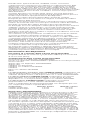
ENGLISH
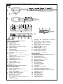
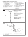
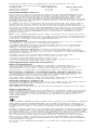
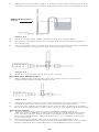
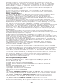
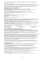
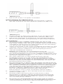
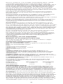
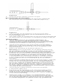
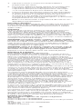
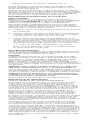
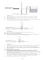
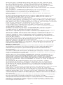
Right angle design with
SIPHONGUARD
A. Side view
B. Top view
C. Inlet connector
D. Reservoir
E. Direction-of-flow arrow
F. Inlet valve
G. Valve seat
H. Valve ball
I. Flat spring
J. Spring calibrating fulcrum
K. O-ring
L. Titanium base plate
M. Cam
N. X-ray cam position indicator
(pressure)
O. Right-hand side x-ray
indicator
P. Stepper motor
Q. Antisiphon device
R. Valve seat
S. Valve ball
T. Central passage
U. Spiral passage
FRANÇAIS
Modèle à angle droit avec
SIPHONGUARD
A. Vue latérale
B. Vue supérieure
C. Raccord d’admission
D. Réservoir
E. Flèche indiquant le sens
d’écoulement
F. Valve d’admission
G. Siège de la valve
H. Bille de la valve
I. Ressort plat
J. Pivot pour l’étalonnage du
ressort
K. Joint torique
L. Plaque de suppport en titane
M. Came
N. Indicateur radiologique
de position de la came
(pression)
O. Indicateur radiologique
latéral droit
P. Moteur pas à pas
Q. Dispositif
anti-siphonnage
R. Siège de la valve
S. Bille de la valve
T. Passage central
U. Passage à spirale
DEUTSCH
Rechtwinklige Ausführung mit
SIPHONGUARD
A. Seitenansicht
B. Draufsicht
C. Einlassverbindung
D. Reservoir
E. Flussrichtungspfeil
F. Einlassventil
G. Ventilsitz
H. Ventilkugel
I. Federscheibe
J. Verstellhebel
K. O-Ring
L. Titan-Basisplatte
M. Nocke
N. Röntgenindikator für
Nockenposition (Druck)
O. Röntgenindikator für rechte
Seite
P. Schrittmotor
Q. Antisiphon
R. Ventilsitz
S. Ventilkugel
T. Hauptkanal
U. Spiralkanal

ii
CODMAN HAKIM Programmable Valves
NEDERLANDS
Haaks ontwerp met
SIPHONGUARD
A. Zijaanzicht
B. Bovenaanzicht
C. Inlaatconnector
D. Reservoir
E. Flowrichtingpijl
F. Inlaatklep
G. Klepzitting
H. Klepkogel
I. Platte veer
J. Kalibreringsdraaipunt voor
veer
K. O-ring
L. Titanium bodemplaat
M. Nok
N. Röntgen-nokpositie-indicator
(druk)
O. Röntgenindicator
rechterzijde
P. Stappenmotor
Q. Antihevelvoorziening
R. Klepzitting
S. Klepkogel
T. Centrale doorgang
U. Spiraalvormige doorgang
ITALIANO
Versione ad angolo retto con
SIPHONGUARD
A. Vista laterale
B. Vista dall’alto
C. Connettore di ingresso
D. Serbatoio
E. Freccia di direzione flusso
F. Valvola di ingresso
G. Sede della valvola
H. Sfera della valvola
I. Molla piatta
J. Fulcro di calibrazione valvola
K. O-ring
L. Piastra con base in titanio
M. Camma
N. Indicatore di posizione della
camma a raggi x (pressione)
O. Indicatore per raggi x destro
P. Motore a passo
Q. Dispositivo antisiphon
R. Sede della valvola
S. Sfera della valvola
T. Passaggio centrale
U. Passaggio a spirale
ESPAÑOL
Diseño de ángulo recto con
SIPHONGUARD
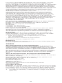
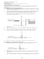
A. Vista lateral
B. Vista superior
C. Conector de entrada
D. Reservorio
E. Flecha de dirección de flujo
F. Válvula de entrada
G. Asiento de la válvula
H. Esfera de la válvula
I. Resorte plano
J. Fulcro de calibración
de resorte
K. Junta tórica
L. Placa de base de titanio
M. Leva
N. Indicador de posición de
leva de rayo X (presión)
O. Indicador de rayos X del
lado derecho
P. Motor por pasos
Q. Dispositivo antisifón
R. Asiento de la válvula
S. Esfera de la válvula
T. Pasaje central
U. Pasaje en espiral
PORTUGUÊS
Concepção em ângulo recto
com SIPHONGUARD
A. Vista lateral
B. Vista de cima
C. Conector de entrada
D. Reservatório
E. Seta de direcção do fluxo
F. Válvula de entrada
G. Apoio da válvula
H. Esfera da válvula
I. Mola plana
J. Fulcro de calibração de mola
K. Anel em “O”
L. Placa de base em titânio
M. Came
N. Indicador de posição do
came para radiografia
(pressão)
O. Indicador direito para
radiografia
P. Motor escalonador
Q. Dispositivo antisiphon
R. Base da válvula
S. Esfera da válvula
T. Passagem central
U. Passagem em espiral

iii
CODMAN HAKIM Programmable Valves
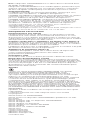
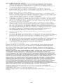
ENGLISH
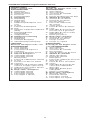
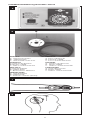
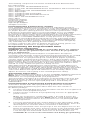
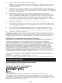
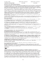
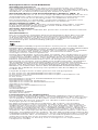
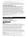
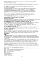
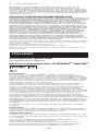
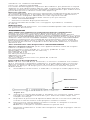
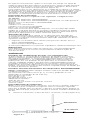
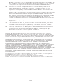
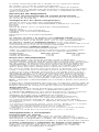
Programmable valve
configurations
A. In-line with SIPHONGUARD
Device
B. In-line with SIPHONGUARD
Device and Platform with
Proximal Tube
C. In-line
D. Right angle with
SIPHONGUARD Device
E. Right angle
F. Cylindrical with prechamber
G. Cylindrical with RICKHAM
Reservoir
H. Cylindrical
I. Micro with RICKHAM reservoir
J. Micro
FRANÇAIS
Configurations de la valve
programmable
A. En-ligne avec l’appareil
SIPHONGUARD
B. En ligne avec le dispositif
SIPHONGUARD avec tubulure
proximale
C. En-ligne
D. Appareil SIPHONGUARD avec
angle droit
E. Angle droit
F. Cylindrique avec préchambre
G. Cylindrique avec réservoir
RICKHAM
H. Cylindrique
I. Micro avec réservoir RICKHAM
J. Micro
DEUTSCH
Konfigurationen des
programmierbaren Ventils
A. In-line mit SIPHONGUARD
Durchflussregler
B. In-line-Ventil mit
SIPHONGUARD
Durchflussregler und Plattform
mit proximalem Schlauch
C. In-line
D. Rechtwinklig mit
SIPHONGUARD
Durchflussregler
E. Rechtwinklig
F. Zylindrisch mit Vorkammer
G. Zylindrisches Ventil mit
RICKHAM Reservoir
H. Zylindrisch
I. Mikro mit RICKHAM Reservoir
J. Mikro
NEDERLANDS
Configuraties programmeerbare
klep
A. Inline met SIPHONGUARD
regelaar
B. Inline met SIPHONGUARD
regelaar en platform met
proximale buis
C. Inline
D. Haaks met SIPHONGUARD
regelaar
E. Haaks
F. Cilindervormig met voorkamer
G. Cilindervormig met RICKHAM
reservoir
H. Cilindervormig
I. Micro met RICKHAM reservoir
J. Micro
ITALIANO
Configurazioni della valvola
programmabile
A. Versione lineare con dispositivo
SIPHONGUARD
B. Lineare con dispositivo
SIPHONGUARD e piattaforma
con tubo prossimale
C. Versione lineare
D. Angolo retto con dispositivo
SIPHONGUARD
E. Angolo retto
F. Cilindrica con precamera
G. Cilindrica con serbatoio
RICKHAM
H. Cilindrica
I. Micro con serbatoio RICKHAM
J. Micro
2

iv
CODMAN HAKIM Programmable Valves
ESPAÑOL
Configuraciones de la válvula
programable
A. En línea con dispositivo
SIPHONGUARD
B. En línea con dispositivo
SIPHONGUARD y plataforma
con tubo proximal
C. En línea
D. Ángulo recto con dispositivo
SIPHONGUARD
E. Ángulo recto
F. Cilíndrica con antecámara
G. Cilíndrica con reservorio
RICKHAM
H. Cilíndrica
I. Micro con reservorio RICKHAM
J. Micro
PORTUGUÊS
Configurações da válvula
programável
A. Válvula em linha com
dispositivo SIPHONGUARD
B. Em linha com o dispositivo
SIPHONGUARD e plataforma
com tubo proximal
C. Em linha
D. Válvula de ângulo recto com
dispositivo SIPHONGUARD
E. Ângulo recto
F. Válvula cilíndrica com
antecâmara
G. Cilíndrica com reservatório
RICKHAM
H. Cilíndrica
I. Microválvula com reservatório
RICKHAM
J. Micro
3B
A
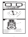
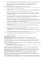
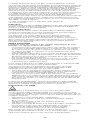
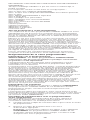
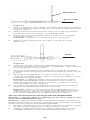
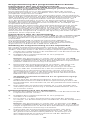
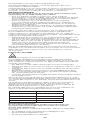
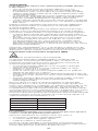
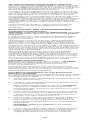
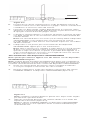
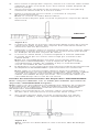
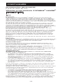
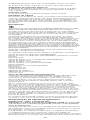
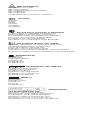
ENGLISH
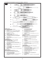
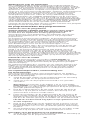
A. Ventricular Catheter
B. Right Angle Adapter
FRANÇAIS
A. Cathéter ventriculaire
B. Adaptateur à angle droit
DEUTSCH
A. Ventrikelkatheter
B. Rechtwinkliger Adapter
NEDERLANDS
A. Ventrikelkatheter
B. Haakse adapter
ITALIANO
A. Catetere ventricolare
B. Adattatore ad angolo retto
ESPAÑOL
A. Catéter ventricular
B. Adaptador en ángulo recto
PORTUGUÊS
A. Cateter ventricular
B. Adaptador de ângulo recto
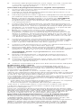
4
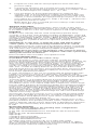
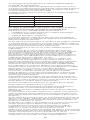
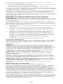
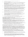
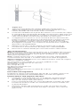
A. Priming adapter
A. Adaptateur d’irrigation
A. Starteradapter
A. Pompadapter
A. Adattatore di irrigazione
A. Adaptador cebador
A. Adaptador de irrigação

v
CODMAN HAKIM Programmable Valves
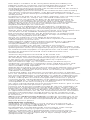
6
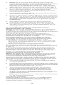
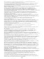
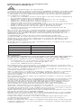
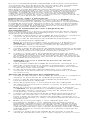
ENGLISH
A. Directional arrows
B. START button
C. Illuminated center hole
FRANÇAIS
A. Flèches de direction
B. Bouton START
C. Orifice central lumineux
DEUTSCH
A. Richtungspfeile
B. START-Taste
C. Beleuchtetes Mittelloch
NEDERLANDS
A. Richtingspijlen
B. START-knop
C. Verlichte centrale opening
ITALIANO
A. Frecce direzionali
B. Pulsante START
C. Foro centrale illuminato
ESPAÑOL
A. Flechas de dirección
B. Botón START
C. Orificio central iluminado
PORTUGUÊS
A. Setas direccionais
B. Botão START
C. Orifício central iluminado
8
7
5

vi
CODMAN HAKIM Programmable Valves
9
10
11
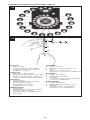
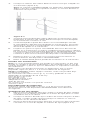
A. White marker
B. Pressure indicator
A. Marqueur blanc
B. Indicateur de pression
A. Weiße Markierung
B. Druckanzeiger
A. Witte markering
B. Drukindicator
A. Marcatore bianco
B. Indicatore di pressione
A. Marca blanca
B. Indicador de presión
A. Marcador branco
B. Indicador de pressão

vii
CODMAN HAKIM Programmable Valves
12
13
ENGLISH
A. Valve outlet
B. Priming adapter with tubing
C. Pyrogen-free sterile saline or
antibiotic solution
FRANÇAIS
A. Évacuation de la valve
B. Adaptateur d’irrigation avec tube
C. Sérum physiologique stérile ou
solution antibiotique apyrogène
DEUTSCH
A. Ventilauslass
B. Starteradapter mit Schlauch
C. Pyrogenfreie sterile
Kochsalzlösung oder
antibiotische Lösung
NEDERLANDS
A. Klepuitlaat
B. Pompadapter met lijnmateriaal
C. Niet-pyrogene steriele
zoutoplossing of antibiotische
oplossing
ITALIANO
A. Uscita valvola
B. Adattatore di irrigazione con
tubo
C. Soluzione sterile salina
apirogena o soluzione antibiotica
ESPAÑOL
A. Salida de válvula
B. Adaptador cebador
con tubo
C. Solución salina estéril apirógena
o solución antibiótica
PORTUGUÊS
A. Saída da válvula
B. Adaptador de irrigação com
tubagem
C. Solução salina esterilizada
apirogénica ou antibiótica

viii
CODMAN HAKIM Programmable Valves
14
15
16
17
18

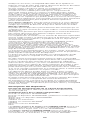
ENGLISH
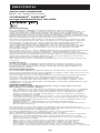
IMPORTANT INFORMATION
Please Read Before Use
CODMAN® HAKIM® Programmable Valves
Description
The CODMAN® HAKIM® Programmable Valve includes a valve mechanism
(Figures 1 & 2) that incorporates a flat 316L stainless steel spring in
which the calibration is accomplished by a combination between a pillar
and a micro-adjustable telescoping fulcrum. The valve chassis is made
of titanium. The ball and cone are manufactured from synthetic ruby.
Intraventricular pressure is maintained at a constant level by the ball
and cone valve seat design.
The pressure setting of the spring in the inlet valve unit is noninvasively
adjusted by the use of an external programmer, which activates the
stepper motor within the valve housing. The programmer transmits a
codified magnetic signal to the motor allowing eighteen pressure settings,
ranging from 30 mm to 200 mm H2O (294 to 1960 Pa) in 10 mm (98 Pa)
increments. These are operating pressures of the valve unit and have been
determined with a flow rate of 15–25 mL H2O per hour.
The valve is classified by its working pressure with a specified flow rate
and not by the opening and closing pressures. The pressure that a valve
sustains with a given flow is the parameter that reflects the working
pressure of the valve once it is implanted. Before shipment, each valve
is calibrated with special equipment. Duplication of these test procedures
cannot be accomplished in the operating room.
The valve is marked with an x-ray detectable direction-of-flow indicator.
Indications
The CODMAN HAKIM Programmable Valves are implantable devices that
provide constant intraventricular pressure and drainage of CSF for the
management of hydrocephalus.
Contraindications
The CODMAN HAKIM Programmable Unitized Valve Systems are not
recommended for atrial placement. Use the nonunitized versions for
this procedure.
These devices are contraindicated in patients receiving anticoagulants or
known to have a bleeding diathesis.
Avoid shunt implantation if infection is present within the body. Delay the
shunt procedure when infections such as meningitis, ventriculitis, peritonitis,
bacteremia, and septicemia are present.
WARNINGS
Subjecting the valve to strong magnetic fields may change the setting
of the valve.
• The use of Magnetic Resonance (MR) systems up to 3 T will not
damage the valve mechanism, but may change the setting of the valve.
Confirm the valve setting after an MRI procedure. See Programming the
Programmable Valve.
• Common magnets greater than 80 gauss, such as household magnets,
loudspeaker magnets, and language lab headphone magnets, may affect
the valve setting when placed close to the valve.
• Magnetic fields generated from microwaves, high-tension wires, electric
motors, transformers, etc., do not affect the valve setting.
Read MRI Information before performing an MRI procedure on a patient
implanted with the programmable valve.
Any magnet may experience a degradation of magnetic field strength as a
consequence of exposure to the significantly stronger magnet field induced
in an MRI procedure.
• Based on the coercivity of the CHPV magnet material, the valve is
resistant to magnetic degradation in a 1.5T MRI.
• Testing of the CHPV valve following exposure to 10 simulated MRI
procedures at 3T indicates there may be demagnetization that,
subsequently, could lead to a reduction in the ability to program the
valve. Please refer to Troubleshooting section should any difficulty in
programming occur.
The SIPHONGUARD® device is intended to reduce the rapid flow of CSF.
It also reduces the ability to prime the shunt system during implantation to
a rate of approximately 0.5 mL/minute.
MRI Information
Do not use the programmer in the MR suite.
1

The CODMAN HAKIM Programmable Valve is considered “MR Conditional”
according to ASTM F 2503. The valve demonstrates no known hazards
when an MRI is performed under the following conditions:
• MRI can be performed at any time after implantation
• Use an MR system with a static magnetic field of 3 T or less
• Use an MR system with a spatial gradient of 720 gauss/cm or less
• Limit the exposure to RF energy to a whole-body-averaged specific
absorption rate (SAR) of 3 W/kg for 15 minutes
• Verify the valve setting after the MRI procedure (see Programming the
Programmable Valve)
In non-clinical testing, the valve produced a temperature rise of 0.4°C at a
maximum whole-body-averaged specific absorption rate (SAR) of 3.0 W/kg
for 15 minutes of MR scanning in a 3 T EXCITE™ General Electric
MR scanner.
MR image quality may be compromised if the area of interest is relatively
close to the device. Distortion may be seen at the boundaries of the artifact.
Therefore, optimization of the MR imaging parameters may be necessary.
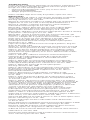
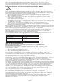
The following chart provides a comparison between the signal void and
imaging pulse sequence at 3 T:
Signal Void Pulse Sequence
1590 mm2T1-SE
1022 mm2T1-SE
2439 mm2GRE
2404 mm2GRE
Precautions
The programmable valves are supplied without a specific programmed
pressure and must be programmed prior to use.
Inspect the sterile package carefully. Do not use if:
• the package or seal appears damaged,
• contents appear damaged, or
• the expiry date has passed.
This is an adjustable valve and the surgeon must take that into account
when evaluating patients. It is important to verify the current pressure
setting as part of any treatment plan.
Do not allow the programming unit or transmitter unit to remain in
environmental extremes.
After exposure of the programming unit or the transmitter unit to
environmental extremes, such as those found in transport or storage,
allow the unit to come within operating range before operating.
Do not program the valve on a metal surface, such as a Mayo stand.
While becoming familiar with valve programming, it is recommended that
the pressure setting of the implanted valve be changed in increments of
no more than ±40 mm H2O (392 Pa) in a 24-hour period. Patients whose
pressure setting has been changed should be carefully monitored during the
first 24 hours post programming. It is recommended that x-rays be taken to
confirm the changes made to valve pressure setting.
Before use, check the programming unit and transmitter unit
connections, settings, and function (see Preimplantation Programming
Familiarization Procedure).
Use only Integra branded programmers to program the pressure of the
CODMAN HAKIM Programmable Valve.
Unauthorized modifications to the programming unit or transmitter unit may
cause a malfunction that could result in serious patient injury or death.
Electrical shock hazard: Do not open the programming unit or transmitter
unit. Refer servicing to qualified service personnel.
Explosion hazard: Do not use the programming unit in the presence of
flammable materials; i.e., anesthetics, solvents, cleaning agents, and
endogenous gases.
Before turning on the 100/120, 220/240 VAC programming unit (catalog
no. 82-3121 or 82-3190), verify that the supply voltage selector on the rear
of the unit is set to the correct voltage for the electrical outlet.
Do not move the transmitter unit during programming.
Never immerse the programming unit or the transmitter unit in any liquid.
Do not sterilize the programming unit or the transmitter.
Use only with components compatible with the dimensions shown in the
Device Description section.
Aseptic technique is necessary in all phases of the use of this product.
Silicone has a low cut and tear resistance; therefore, exercise care when
placing ligatures so as not to tie them too tightly. The use of stainless steel
ligatures on silicone rubber is not recommended.
Do not use sharp instruments when handling the silicone valve or catheter;
use shod forceps. Cuts or abrasions from sharp instruments may rupture or
tear the silicone components.
Do not fold or bend the valve during insertion. Incorrect insertion may cause
rupture of the silicone housing.
2

To better stabilize the position of the valve underneath the scalp, proper
valve placement is required. Place the flat underside of the valve against the
bone, with the round top surface facing upward.
Verify proper placement and integrity of ligatures at all tubing junctions to
prevent obstruction of the catheter lumen and tears or abrasions of the
silicone tubing.
Do not fill, flush, or pump the valve with fluid in which cotton, gauze,
or other lint-releasing material has been soaked.
Exercise extreme care to prevent the silicone components of the system
from coming in contact with bare fingers, towels, drapes, talc, or any linty
or granular surfaces. Silicone rubber is highly electrostatic and, as a result,
attracts airborne particles and surface contaminants that could produce
tissue reaction.
After implantation, avoid unnecessary pumping of the prechamber and
pumping chamber to prevent rapid alteration of the intraventricular pressure.
Cylindrical Valves only: Before closing the scalp incision (or mastoidal
incision, if a two-step passage technique is employed), confirm that the
direction-of-flow arrow on the valve faces up.
Adverse Events
Devices for shunting CSF may have to be replaced at any time due to
medical reasons or failure of the device.
Keep patients with implanted shunt systems under close observation for
symptoms of shunt failure.
Complications of implanted shunt systems include mechanical failure, shunt
pathway obstruction, infection, foreign body (allergic) reaction to implants,
and CSF leakage along the implanted shunt pathway.
Clinical signs such as headache, irritability, vomiting, drowsiness, or
mental deterioration may be signs of a nonfunctioning shunt. Low-grade
colonization, usually with Staph. epidermidis, can cause, after an interval
from a few days to several years, recurrent fevers, anemia, splenomegaly,
and eventually, shunt nephritis or pulmonary hypertension. An infected shunt
system may show redness, tenderness, or erosion along the shunt pathway.
Accumulation of biological matter (i.e. blood, protein accumulations, tissue
fragments, etc.) in the programming mechanism can cause inability of the
device to be reprogrammed.
Clogging of the programmable valve with biological matter can cause the
valve to become unresponsive to attempts to change the pressure setting.
Do not use excessive force if attempting to remove the catheter(s).
Excessive force can cause the catheter to break, leaving part of the catheter
within the body.
Excessive CSF drainage can cause subdural hematomas, slit-like ventricles,
and in infants, sunken fontanelles.
Particulate matter such as blood clots, brain fragments, or other tissue
particles can obstruct the ventricular catheter. Also, the ventricular catheter
can become obstructed by excessive reduction of ventricle size.
If not properly located in the lateral ventricle, the catheter can become
embedded in the ventricular wall or choroid plexus.
Fibrous adhesions can bind the catheter to the adjacent choroids plexus
or to the ventricular wall. Gentle rotation may free the catheter. DO NOT
REMOVE THE CATHETER FORCEFULLY. If the catheter cannot be
removed without force, it is recommended that it remain in place, rather
than risk intraventricular hemorrhage.
The ventricular catheter can be withdrawn from, or lost in, the lateral
ventricles of the brain if it becomes detached from the shunt system.
Blunt or sharp trauma to the head in the region of implant or repetitive
manipulation of the valve during implant may compromise the shunt.
Check valve position and integrity after occurrence.
Device Description
Programmable Valve Operating Pressure
30 to 200 mm H2O (294 to 1960 Pa) programmable in steps of
10 mm H2O (98 Pa)
Programmable Valve Configurations
In-line with SIPHONGUARD Device
In-line with SIPHONGUARD Device and Platform with Proximal Tube
In-line
Right Angle with SIPHONGUARD Device
Right Angle
Cylindrical with Prechamber
Cylindrical with RICKHAM® Reservoir
Cylindrical
Micro with RICKHAM Reservoir
Micro
CODMAN HAKIM In-line and Right Angle Valves include a programmable
valve with a low profile and flat bottom, and an in-line or right angle integral
reservoir with or without SIPHONGUARD.
CODMAN HAKIM Cylindrical Valves include a programmable valve, a
pumping chamber, and an outlet valve available with a prechamber, without
a prechamber, or with a RICKHAM reservoir.
CODMAN HAKIM Micro Valves include a programmable valve with or
without an integral RICKHAM reservoir.
3

All programmable valve configurations are designed for use with
components having the following dimensions:
Component Inner Diameter Outer Diameter
Ventricular Catheter 1.4 mm 2.7 mm
Drainage Catheter 1.0 mm 2.2 mm
SIPHONGUARD Device
CSF flows through the inlet valve and enters the SIPHONGUARD Device,
where it flows into two internal passages. Under normal conditions, the
majority of CSF flows through a central ruby ball and cone valve, and
exits directly out of the distal port of the SIPHONGUARD Device. The
remaining CSF travels through a spiral passage that surrounds the central
passage, and joins the fluid passing through the central passage, distal to
the ball and cone valve.
A sudden increase in CSF flow will close the ball and cone valve and the
entire volume of CSF will be forced through the longer spiral passage,
effectively slowing the rate at which CSF is shunted from the brain. Once
the flow rate entering the SIPHONGUARD Device decreases, the ruby ball
separates from the valve seat, opening the central passage. As long as
CSF continues to be shunted from the ventricles, flow through the spiral
passage of the SIPHONGUARD Device never stops, regardless of the
patient’s position.
Note: The SIPHONGUARD Device will not activate at low CSF flow rates.
The SIPHONGUARD Device has a rigid enclosing shell of polyethersulfone
to prevent inadvertent closure (and subsequent reduction or blockage of
CSF flow) caused by externally applied pressure.
How Supplied
The Valve includes a programmable valve, instructions for use, straight
connector(s)*, introducer**, and priming adapter***.
The Valve System includes a programmable valve, 14 cm ventricular
catheter, 120 cm peritoneal catheter, instructions for use, right angle
adapter, and priming adapter***.
The Valve System, Unitized, includes a programmable valve, 14 cm
ventricular catheter, 85 cm slit**** or 120 cm unitized peritoneal catheter,
instructions for use, straight connector(s)*, introducer**, right angle adapter,
and priming adapter***.
*Straight connectors provided with Cylindrical, Micro, and In-line with
SIPHONGUARD and Platform with Proximal Tube versions only.
**Introducers provided with Cylindrical versions only.
***Priming adapter provided with In-line, Right Angle, and Micro versions only.
****85 cm slit catheter packaged with 82-3853 only.
Components and Accessories
Valve Programmer
The valve programmer, available in 100/120 or 220/240 VAC, is
supplied with a transmitter head, transmitter cord, and carrying case.
The programmer is sold nonsterile and available separately. The
programmer is required for changing the pressure setting of the valves.
Ventricular Catheter and Right Angle Adapter (Figure 3)
The ventricular catheter is a 14 cm straight ventricular catheter molded
of radiopaque silicone elastomer with x-ray detectable dots and a
preassembled stainless steel introducing stylet.
The right angle adapter, made of PROLENE® Material, allows 90 degree
bending of the ventricular catheter at the burr hole site.
Priming Adapter (Figure 4)
The priming adapter, provided with the In-line, Right Angle, and Micro Valves,
facilitates preimplantation irrigation to the valve and catheters.
Straight Connector
The straight connector joins the proximal and distal catheters to the valve.
Valve Introducer
A disposable polyethylene valve introducer is supplied to aid in passing the
valve and drainage catheter from the burr hole site to a mastoidal incision,
when a two-step passage technique is used. Because of the malleability
of this introducer, it can be preformed to a desired curvature prior to
valve placement.
Sterility
The CODMAN HAKIM Programmable Valve Systems are intended for SINGLE
USE ONLY; DO NOT RESTERILIZE. Use aseptic technique in all phases of
handling. Integra will not be responsible for any product that is resterilized,
nor accept for credit or exchange any product that has been opened but not
used.
Integra single-use devices have not been designed to undergo or withstand
any form of alteration, such as disassembly, cleaning or re-sterilization, after
a single patient use. These devices are intended to come into contact with
the central nervous system and the ability does not currently exist to destroy
possible contaminates such as Creutzfeldt-Jakob Disease. Reuse can
also compromise device performance and any usage beyond the design
intent of this single-use device can result in unpredictable use hazards or
loss of functionality. (THIS STATEMENT APPLIES TO NON-IMPLANTABLE
COMPONENTS ONLY.)
As long as the individual package is not opened or damaged, the product
is sterile.
4

The following components have been tested and were determined to
be nonpyrogenic:
Valve, In-line with SIPHONGUARD Device
Valve, In-line with SIPHONGUARD Device and Platform with Proximal Tube
Valve, In-line
Valve, Right Angle with SIPHONGUARD Device
Valve, Right Angle
Valve, Cylindrical with Prechamber
Valve, Cylindrical with RICKHAM Reservoir
Valve, Cylindrical
Valve, Micro with RICKHAM Reservoir
Valve, Micro
Peritoneal Catheter
Ventricular Catheter
Priming Adapter
Right Angle Adapter
Straight Connector
Preimplantation Performance Testing
Each CODMAN HAKIM Programmable Valve is individually tested on
a component level to ensure conformance to the advertised performance
characteristics. Each valve is dynamically tested at six different settings
for proper dynamic opening pressure over the entire performance range.
Performing a manometer test is not recommended, as it is susceptible
to environmental factors. Manometer testing yields a result that is not
physiologic in nature and for which manufacturers do not specify performance
ranges. If the surgeon insists upon performing manometer testing for
confirmation of CODMAN HAKIM Valve closing pressures, it is possible,
but is not recommended. When performed correctly, manometer testing
generates valve closing pressures similar to the CODMAN HAKIM Valve
opening pressure setting. However, closing pressure results will typically
vary noticeably from the opening pressure setting.
For those surgeons who wish to perform functional testing, please see
Preimplantation Performance Testing in the Appendix.
Programming the Programmable Valve
Programmer Information
WARNING: The CODMAN HAKIM Programmable Valves are supplied
without a specific programmed pressure and must be programmed
prior to implantation.
Programming must be performed prior to implantation through the
nonsterile outer package. Perform programming postoperatively as needed.
The programmer consists of two parts, the programming unit and the
transmitter unit. The programming unit control panel (Figure 5) features
a power switch, programming instructions, and a representation of the
programmable portion of the valve system as it appears when x-rayed. This
representation also incorporates the 18 pressure selection buttons. Eighteen
LEDs, corresponding to the position of the valve pressure indicator when
viewed on x-ray, confirm the pressure setting chosen.
After depressing the desired pressure selector button, an LED lights in the
programming unit. The lighted LED corresponds exactly with the position of
the pressure indicator on the valve. When programming begins, the transmitter
unit emits a sequentially coded electromagnetic signal. The stepper motor
of the valve detects the signal and rotates the cam assembly, which, in turn
adjusts the tension of the spring to the selected pressure setting.
Transmitter Information
Note: This Transmitter Information is for the CODMAN HAKIM Programmers
ONLY. When using another Integra programmer, please refer to the
instructions for use packaged with your programmer.
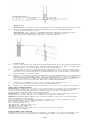
The transmitter unit (Figure 6) incorporates an illuminated center hole and
directional arrows to aid in proper positioning over the valve. It connects
to the programming unit via a pronged plug and is activated by the
START button.
Preimplantation Programming Familiarization Procedure
To become familiar with valve programming, perform the following
preimplantation programming procedure while the valve remains in
the blister package.
1. Insert the pronged plug from the transmitter unit into the receptacle at
the back of the programming unit.
2. Plug the power cord from the programming unit into an appropriate
power source.
Note: The instructions contained in steps 3 through 6 are for the
CODMAN HAKIM Programmers ONLY. When using another Integra
programmer, please refer to the instructions for use packaged with
your programmer.
3. Press the programming unit’s power button to the ON position. Both
the ON button and Instruction 1 on the panel will illuminate. Press the
desired pressure selection button; Instruction 2 illuminates.
4. Place the transmitter unit’s four prongs in the four depressions in the
blister around the inlet valve. Point the arrow on the transmitter unit in
the same direction as the arrow on the blister (the direction of flow).
Look through the illuminated center hole of the transmitter unit.
CAUTION: Do not move the transmitter unit during programming.
5

5. Push the transmitter unit’s START button. Instruction 3 on the control
panel illuminates. During programming, the pressure selector buttons
light sequentially until the selected pressure setting is attained.
6. When programming is completed (approximately five seconds),
Instruction 4 on the panel illuminates momentarily and a
buzzer sounds.
Postimplantation Programming Procedure
1. Insert the pronged plug from the transmitter unit into the receptacle
at the back of the programming unit.
2. Plug the power cord from the programming unit into an appropriate
power source.
3. Prior to programming, it is advisable to take an x-ray of the patient’s
head to verify the valve’s pressure setting and position.
Note: The instructions contained in steps 4 through 11 are for the
CODMAN HAKIM Programmers ONLY. When using another Integra
programmer, please refer to the instructions for use packaged with
your programmer.
4. Press the programming unit’s power button ON. The ON button
and Instruction 1 on the panel illuminate. Press the desired pressure
selection button; Instruction 2 on the programmer panel and the
center hole of the transmitter unit will illuminate.
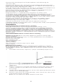
5. Note: It is not necessary to shave the scalp for this procedure.
Palpate the scalp to locate the implanted valve, specifically, the inlet
valve, located distal of the reservoir. A fluoroscopic screen may assist
in this process. Place the tip of the left forefinger precisely over the
inlet valve, keeping the index finger parallel to the valve system and
pointing in the direction of flow (Figure 7).
6. Place the transmitter unit’s four prongs around the inlet valve so that
the prongs are sitting on the scalp. The arrows on the transmitter unit
should be parallel to the forefinger and pointing in the direction of
flow (Figure 8).
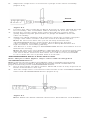
7. Center the transmitter unit so that the illuminated opening is directly
above the nail of the index finger (Figure 9).
8. Remove finger from the valve and push the transmitter unit’s START
button (Figure 10). Instruction 3 on the control panel illuminates,
indicating that the valve is programming.
CAUTION: Do not move the transmitter unit during programming.
9. During programming, the pressure selector buttons light sequentially
until the selected pressure setting is attained.
10. When programming is completed (approximately five seconds),
Instruction 4 on the panel illuminates momentarily and
a buzzer sounds.
11. Verify the valve pressure setting with an x-ray.
X-Raying the Valve
Note: The instructions contained in X-Raying the Valve are for the
CODMAN HAKIM Programmers ONLY. When using another Integra
programmer, please refer to the instructions for use packaged with
your programmer.
It is advisable to x-ray the complete system immediately after implantation
to have a permanent record of component placement and to verify valve
pressure. It is also advisable to x-ray the valve whenever valve pressure
is reprogrammed.
Use an x-ray with intensifying TV screen, or an x-ray plate to confirm proper
valve pressure. When documenting the valve pressure with x-rays, take care
when positioning so that:
• the nonimplanted side of the head rests on the plate (the implanted side
is uppermost from the plate), and,
• the inlet valve is parallel to the x-ray plate.
Viewing the x-ray, the white marker on the valve indicates the right-hand
side of the valve. The pressure indicator on the white ring indicates the
chosen pressure setting (Figure 11).
There is a direct correlation between the position of the programming unit
control panel pressure selector buttons and the position of the pressure
indicator on the valve as seen when x-rayed. Note that when the valve is
programmed to 70, 120, or 170, the pressure indicator aligns with the “X”
in the center of the valve (Figure 12).
Programming Procedure in Case of an Inverted Valve
Note: The instructions contained in Programming Procedure in Case of
an Inverted Valve are for the CODMAN HAKIM Programmers ONLY. When
using another Integra programmer, please refer to the instructions for use
packaged with your programmer.
An inverted valve can be diagnosed on x-ray; the white marker will appear on
the left side of the valve, instead of the right side. Programming the inverted
valve requires a “double programming” to obtain the desired pressure setting.
6

1. Program the valve with the valve programmer at the 200 valve
pressure setting.
2. Calculate the following: 210 (constant) minus the desired pressure
setting equals the programming pressure setting. For example, where
70 is the desired pressure setting: 210 – 70 = 140.
3. Push the button for the programming pressure setting (in this
example, 140) on the programmer; hold the transmitter in place for
approximately 5 seconds until the confirmation tone is heard. If the
surgeon is unsure whether the reprogramming took place, he or she
must repeat the complete process, Steps 1 through 3, otherwise the
programming will be incorrect.
Note: When the valve is inverted, pressure settings of 190 and 200
are not possible to program.
Surgical Procedure
There are a variety of surgical techniques, which can be used to place
the CODMAN HAKIM Programmable Valves. The surgeon should choose
in accordance with his or her own clinical experience and medical judgment.
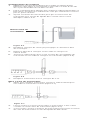
Irrigation
Hold the valve vertically with the outlet end pointing upward. Using
a syringe, or the action of the pumping chamber (if applicable), slowly and
gently fill the entire valve system (Figure 13) with pyrogen-free, sterile saline
solution or appropriate antibiotic solution. Note: A priming adapter with
inlet tubing is provided with the In-line, Right Angle, and Micro versions to
facilitate irrigation (Cylindrical Valves incorporate a pumping chamber for
this purpose).
CAUTION: Do not fill, flush, or pump the valve with fluid in which
cotton, gauze, or other lint-releasing material has been soaked.
Once fluid flows from the outlet end of the drainage catheter, occlude the
inlet tubing of the valve system with shod forceps close to the ventricular
end, and remove the syringe and priming adapter (if applicable).
CAUTION: Avoid any unnecessary pumping of the system to prevent
overdrainage of the ventricles. Over irrigation of the valve system may
damage the internal mechanism.
Please record the valve lot number on the patient’s chart.
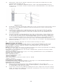
Clearing Obstructions
(Cylindrical with Prechamber Valves only)
To check the patency of the ventricular catheter, occlude the tubing
between the prechamber and the valve unit with finger pressure (Figure 14).
Press the prechamber. If the prechamber does not compress easily and
does not return immediately to its original shape, or if the prechamber
compresses easily but does not refill immediately, the ventricular catheter
may be occluded. To correct this situation, first allow the prechamber to
refill. Then, occlude the tubing between the prechamber and the valve
unit with finger pressure and press the prechamber firmly. This forces fluid
back through the ventricular catheter, helping to remove the obstruction.
If necessary, repeat this procedure.
In some circumstances, the use of a syringe (with 25-gauge Huber type
needle) is necessary to remove the obstruction. Occlude the tubing
between the prechamber and the valve unit with finger pressure. Using light
pressure, inject sterile, nonpyrogenic saline solution into the prechamber
(Figure 15).
To test the patency of the tubing between the prechamber and the valve
unit, occlude the tubing between the prechamber and the valve unit
with pressure. Press and release the prechamber. If the prechamber
immediately returns to its original shape after compression, remove finger
from the tubing and press the pumping chamber. If the pumping chamber
compresses readily but does not immediately return to its original shape,
there may be an obstruction between the prechamber and valve unit. To
remedy this situation, occlude the tubing between the prechamber and
the ventricular catheter (Figure 16). Firmly press the prechamber with the
adjoining finger to force fluid forward through the valve unit and drainage
catheter. If necessary, repeat.
Occasionally, it may be necessary to use a syringe with 25-gauge Huber
type needle to dislodge the obstruction. Occlude the tubing proximal to
the prechamber. Using light pressure, inject sterile, nonpyrogenic saline
solution into the prechamber (Figure 17).
To test the patency of the valve outlet or drainage catheter, press on the
pumping chamber. If the pumping chamber resists compression, the valve
outlet or drainage catheter may be obstructed. To dislodge the obstruction,
press the valve unit forcefully, then release it to permit the prechamber
to refill.
Reservoir Injection
These instructions apply to the following valve configurations:
In-line with SIPHONGUARD Device
In-line with SIPHONGUARD Device and Platform with Proximal Tube
In-line
Right Angle with SIPHONGUARD Device
Right Angle
Cylindrical with Prechamber
Cylindrical with RICKHAM Reservoir
Micro with RICKHAM Reservoir
To inhibit coring of the reservoir cap, use a Huber type needle
(24- or 26-gauge) to penetrate the dome. Insert the needle at an oblique
angle to achieve the greatest yield of CSF and to prevent the needle point
from piercing the ventricular catheter (Figure 18).
7

Troubleshooting
If valve function is adversely affected by accumulations of biological matter,
it may be possible to dislodge the material and restore proper function
through one of the following methods:
• Flushing and/or pumping the valve (only for those valves
without SIPHONGUARD)
• Multiple programming attempts
If these remedial steps fail to rectify the problem, replace the valve.
Bibliography
Adams RD, Fisher M, Hakim S, Ojemann RG, Sweet WH: Symptomatic
occult hydrocephalus with “normal” cerebrospinal fluid pressure.
New Eng J Med 273: 117–126, 1965.
Bayston R: Serological surveillance of children with CSF shunting devices.
Supplement 35: 104–110, 1975, to Develop Med Child Neurol 17.
Bayston R, Swinden J: Aetiology & prevention of Shunt Nephritis.
Zeitschrift für Kinderchirurgie 28: 377–384, 1979.
Black P McL, Hakim R, Bailey NO: The Use of the Codman-Medos
Programmable Hakim Valve in the Management of Patients with
Hydrocephalus: Illustrative Cases. Neurosurgery 34: 6, 1994.
Black P McL: Idiopathic normal-pressure hydrocephalus. Results of shunting
in 62 patients. J Neurosurg 53: 371–377, 1980.
Black P McL, Tzouras A, Ojemann RG: CSF shunts for dementia, gait
disturbance, and incontinence, Clinical Neurosurgery.
Cohen SJ, Callaghan RP: A syndrome due to bacterial colonisation of Spitz-
Holter valves. A review of 5 cases, Brit Med J 2: 677–680, 1961.
Drake JM, Kestle JRW, Milner R, et al: Randomized Trial of
Cerebrospinal Fluid Shunt Valve Design in Pediatric Hydrocephalus.
Neurosurgery 43: 2, 1998.
Fager CA: Complicated and unusual neurosurgical problems, Surg Clin
N Am 48: 637–642, 1968.
Guthrie TC, Dunbar HS, Karpell B: Ventricular size and chronic increased
intracranial venous pressure in the dog. J Neurosurg 33: 407–414, 1970.
Hakim C: The physics and physiopathology of the hydrauIic complex
of the central nervous system (The Mechanics of Hydrocephalus and
Normal Pressure Hydrocephalus). Ph.D. Thesis, Massachusetts Institute
of Technology, 1985.
Hakim S, Zuluaga A, Cabrera O: Derivación ventriculoatrial para el
tratamiento de la hidrocefália por medio de la válvula de Hakim.
Tesis de grado, Facultad de Medicina, Universidad Javeriana,
Bogotá, Colombia, 1964.
Hakim S, Adams RD: The special clinical problem of symptomatic
hydrocephalus with normal cerebrospinal fluid pressure. Observations on
cerebrospinal fluid hydrodynamics. J Neurol Sci 2: 307–327, 1965.
Hakim S, Adams RD, Fisher CM: Occult hydrocephalus.
New Eng J Med 274: 466, 1966.
Hakim S: Observations on the physiopathology of the CSF pulse and
the prevention of ventricular catheter obstruction in valve shunts.
Hydrocephalus and Spina Bifida. Supplement 20: 42–48, 1970, to
Develop Med Child Neurol.
Hakim S: Biomechanics of hydrocephalus, in Harbert JC (ed):
Cisternography and Hydrocephalus, Charles C. Thomas, Springfield, IL,
25–55, 1972.
Hakim S, Duran de la Roche F, Burton JD: A critical analysis of valve
shunts used in treatment of hydrocephalus. Develop Med Child Neurol
15: 230–255, 1973.
Hakim S: Algunas observaciones sobre la presión del L.C.R. Sindrome
hydrocefálico en el adulto con presión normal del L.C.R. (Presentación de
un nuevo sindrome.) Tesis de grado. Facultad de Medicina, Universidad
Javeriana, Bogotá, Colombia, 1964. Available in English as: Some
observations on CSF pressure. Hydrocephalic syndrome in adults with
“normal” CSF pressure. (Recognition of a new syndrome.)
Hakim S, Venegas JG, Burton JD: The physics of the cranial cavity,
hydrocephalus, and normal pressure hydrocephalus: mechanical
interpretation and mathematical model. Surg Neurol 5: 187–210, 1976.
Hakim S, Hakim C: A biomechanical model of hydrocephalus and its
relationship to treatment. Hydrocephalus, edited by K Shapiro, A Marmarou,
and H Portnoy. 143–160. Raven Press, New York, 1984.
Hammock MK, Milhorat TH, Earle K, DiChiro C: Vein of Galen ligation of the
primate. J Neurosurg 34: 77–83, 1971.
Leheta F: Erfahrungen mit dem Cordis-Hakim-Ventil. Zbi Neurochir
33: 69–74, 1972.
Mori K: Management of Idiopathic Normal Pressure Hydrocephalus: A Multi
Institutional Study Conducted in Japan. J Neurosurg 2: 95, 2001.
Nulsen FE, Spitz EB: Treatment of hydrocephalus by direct shunt from
ventricle to jugular vein. Surg Forum 2: 399–403, 1952.
O’Brien M, Parent A, Davis B: Management of ventricular shunt infections.
Child’s Brain 5: 304–309, 1979.
Ojemann RG: Initial experience with the Hakim valve for ventriculovenous
shunt. J Neurosurg 28: 283–287, 1968.
8

Ojemann RG: Normal pressure hydrocephalus. Clin Neurosurg 18:
337–370, 1971.
Ojemann RG, Black P McL: Evaluation of the patient with dementia and
treatment of normal pressure hydrocephalus. In: Wilkins RH, Regachary SS
(eds). Neurosurgery. McGraw Hill, 1984.
Penn RD, Bacus JW: The brain as a sponge: a computed tomographic look
at Hakim’s Hypothesis. Neurosurgery 14: 670–675, 1984.
Raimondi AJ, Yashon D, Matsumoto S, Reyes C: Increased intracranial
pressure without lateralizing signs, the “midline syndrome.”
Neurochirurgia 10: 197–209, 1967.
Rayport M, Reiss J: “Hydrodynamic Properties of certain shunt
assemblies for the treatment of hydrocephalus, Part I: Report of a case
of communicating hydrocephalus with increased cerebrospinal fluid
production treated by duplication of shunting device.” Part II: Pressure-flow
characteristics of the Spitz-Holter, Pudenz-Meyer, and Cordis-Hakim shunt
systems. J Neurosurg 30: 455–467, 1969.
Reinprecht A, Dietrich W, Bertalanffy A, Czech T: The Medos Hakim
Programmable Valve in the Treatment of Pediatric Hydrocephalus.
Childs Nerv Syst 13: 588–594, 1997.
Zemack G, Romner B: Seven-year clinical experience with the
CODMAN HAKIM programmable valve: a retrospective study of 583 patients.
Neurosurg Focus 7: 4, 1999.
APPENDIX
Preimplantation Performance Testing
Although Integra does not recommend functional testing, some
surgeons may choose to do so. Before testing, it is extremely important
that a CODMAN HAKIM Valve with or without SIPHONGUARD Device be
flushed of all air bubbles. Air bubbles within the CODMAN HAKIM Valve or
SIPHONGUARD Device produce inaccurate manometer test results. The
presence of air bubbles can reduce the cross-sectional area of the flow path,
increase system resistance, and impede the flow of fluid through the system
during testing.
SIPHONGUARD Device Functional Testing
Equipment Required (use all sterile equipment, perform testing under
sterile conditions)
One manometer, wide-bore (e.g. 3.5 mm), graduated in mm (available in
lengths from 38 to 60 cm)
One 4-way stopcock
One syringe, 5 mL
One syringe filter, 5 µm
Tubing adapters
Silicone tubing
One male luer connector with 1/16 in. barb
Saline solution
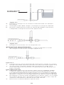
Flushing Procedure
Note: At a rate of 0.5 mL/minute, unitized versions require 2–3 minutes
to complete flushing. This is the time required for fluid to fill the valve and
exit the distal catheter. Allot additional time to ensure the system is free of
air bubbles.
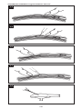
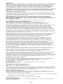
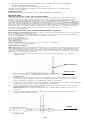
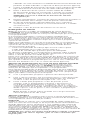
1. Assemble manometer, stopcock, syringe, and tubing (Figure A-1).
Manometer
To Valve
Figure A-1
2. Detach syringe from assembly and fill the syringe with sterile saline
solution using the 5 µm filter in-line. Detach the filter after filling
the syringe.
3. Set the valve opening pressure to 30 mm H2O (294 Pa) while the valve
remains in its sterile package.
4. Remove valve from the sterile package, and connect the valve to the
manometer/syringe assembly.
Note: Do not attach the distal catheter at this time.
9

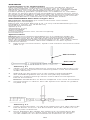
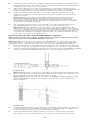
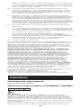
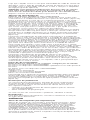
5. Adjust the stopcock to connect the syringe to the valve assembly
(Figure A-2).
Valve
Figure A-2
6. Position the valve vertically to direct the flow of saline upward through
the assembly. This orientation aids in flushing air from the system.
7. Using the syringe, gently flush saline through the system while
gently depressing the prechamber to purge air bubbles from the
valve assembly.
8. Attach the distal catheter and continue to flush the system using the
syringe until saline solution exits the end of the distal catheter.
Note: An excessive flow rate (>0.75 mL/min) activates the
SIPHONGUARD Device and creates the impression that the
valve is distally occluded. In reality, flow is being diverted to the
high resistance secondary pathway.
9. The device is now ready for SIPHONGUARD Device Functional Test or
Manometer Testing.
Note: All valves are susceptible to damage due to excessive flow rate
during testing. Take extreme care when flushing a valve as damage
can occur when excessive flow rates are used. It is recommended
to use a flow rate of no greater than 0.5 mL/min.
SIPHONGUARD Device Functional Test
Note: This procedure applies only to valves with an integrated
SIPHONGUARD Device.
Note: Perform this procedure immediately after completing the flushing
procedure. This procedure is designed to provide visual confirmation of
proper functioning of the SIPHONGUARD Device.
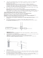
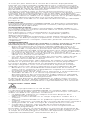
1. Use a full syringe of saline solution attached to the 4-way stopcock to
fill the manometer to the top.
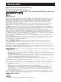
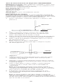
2. Turn the stopcock to connect the manometer to the CODMAN HAKIM
Valve and SIPHONGUARD Device (Figure A-3).
Figure A-3
Note: Attach the distal catheter at this time, flushed free of air bubbles.
10

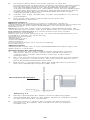
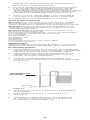
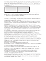
3. Bring the end of the distal catheter level with the fluid level in the
manometer (Figure A-4).
Note: The CODMAN HAKIM Valves with SIPHONGUARD Device
must lie on a sterile surface and remain undisturbed for the duration
of the test.
Figure A-4
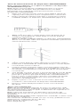
4. Hold the catheter distal tip adjacent to the manometer and slowly lower
the end of the distal catheter until the fluid level in the manometer
begins to drop.
5. Continue to lower the catheter tip at a rate that exceeds the drop
rate of the fluid level in the manometer. As you do so, you will note
a corresponding increase in the rate of descent of the fluid level in
the manometer.
6. A point will be reached where the rate of descent of the fluid level
in the manometer dramatically decreases, but does NOT stop. This
is the point at which the SIPHONGUARD Device primary pathway
closes and flow diverts to the higher resistance secondary pathway.
This confirms proper functioning of the SIPHONGUARD Device.
7. Repeat Steps 3 through 6 as necessary to reconfirm SIPHONGUARD
Device function.
8. Remove distal catheter for manometer testing of valve.
Manometer Testing
Note: Performing a manometer test is not recommended as this test
is susceptible to environmental factors and yields a result that is not
physiologic in nature and for which manufacturers do not specify
performance ranges.
Note: Perform this test only on devices that have been prepared according
to Steps 1 through 8 in Flushing Procedure.
Equipment Required (use all sterile equipment, perform testing under
sterile conditions)
One manometer, wide-bore (e.g. 3.5 mm), graduated in mm (available in
lengths from 38 to 60 cm)
One 4-way stopcock
One syringe, 5 mL
One syringe filter, 5 µm
Tubing adapters
Silicone tubing
One male luer connector with 1/16 in. barb
Saline solution
Flushing Procedure
Prepare the valve following Steps 1 through 8 in SIPHONGUARD Device
Functional Testing, Flushing Procedure.
Equipment Setup
1. Disconnect the valve from the tubing leading to the stopcock.
Perform this step with the valve submerged in a water bath so as not
to reintroduce air into the valve.
2. Place the end of the tubing leading from the stopcock into the water
bath. Position the tubing so that the end does not come into contact
with the sides of the bath.
11
A página está carregando...
A página está carregando...
A página está carregando...
A página está carregando...
A página está carregando...
A página está carregando...
A página está carregando...
A página está carregando...
A página está carregando...
A página está carregando...
A página está carregando...
A página está carregando...
A página está carregando...
A página está carregando...
A página está carregando...
A página está carregando...
A página está carregando...
A página está carregando...
A página está carregando...
A página está carregando...
A página está carregando...
A página está carregando...
A página está carregando...
A página está carregando...
A página está carregando...
A página está carregando...
A página está carregando...
A página está carregando...
A página está carregando...
A página está carregando...
A página está carregando...
A página está carregando...
A página está carregando...
A página está carregando...
A página está carregando...
A página está carregando...
A página está carregando...
A página está carregando...
A página está carregando...
A página está carregando...
A página está carregando...
A página está carregando...
A página está carregando...
A página está carregando...
A página está carregando...
A página está carregando...
A página está carregando...
A página está carregando...
A página está carregando...
A página está carregando...
A página está carregando...
A página está carregando...
A página está carregando...
A página está carregando...
A página está carregando...
A página está carregando...
A página está carregando...
A página está carregando...
A página está carregando...
A página está carregando...
A página está carregando...
A página está carregando...
A página está carregando...
A página está carregando...
A página está carregando...
A página está carregando...
A página está carregando...
A página está carregando...
A página está carregando...
A página está carregando...
A página está carregando...
A página está carregando...
A página está carregando...
A página está carregando...
A página está carregando...
A página está carregando...
-
 1
1
-
 2
2
-
 3
3
-
 4
4
-
 5
5
-
 6
6
-
 7
7
-
 8
8
-
 9
9
-
 10
10
-
 11
11
-
 12
12
-
 13
13
-
 14
14
-
 15
15
-
 16
16
-
 17
17
-
 18
18
-
 19
19
-
 20
20
-
 21
21
-
 22
22
-
 23
23
-
 24
24
-
 25
25
-
 26
26
-
 27
27
-
 28
28
-
 29
29
-
 30
30
-
 31
31
-
 32
32
-
 33
33
-
 34
34
-
 35
35
-
 36
36
-
 37
37
-
 38
38
-
 39
39
-
 40
40
-
 41
41
-
 42
42
-
 43
43
-
 44
44
-
 45
45
-
 46
46
-
 47
47
-
 48
48
-
 49
49
-
 50
50
-
 51
51
-
 52
52
-
 53
53
-
 54
54
-
 55
55
-
 56
56
-
 57
57
-
 58
58
-
 59
59
-
 60
60
-
 61
61
-
 62
62
-
 63
63
-
 64
64
-
 65
65
-
 66
66
-
 67
67
-
 68
68
-
 69
69
-
 70
70
-
 71
71
-
 72
72
-
 73
73
-
 74
74
-
 75
75
-
 76
76
-
 77
77
-
 78
78
-
 79
79
-
 80
80
-
 81
81
-
 82
82
-
 83
83
-
 84
84
-
 85
85
-
 86
86
-
 87
87
-
 88
88
-
 89
89
-
 90
90
-
 91
91
-
 92
92
-
 93
93
-
 94
94
-
 95
95
-
 96
96


Integra CODMAN® HAKIM® Programmable Valves Instruções de operação
- Tipo
- Instruções de operação
em outras línguas
- español: Integra CODMAN® HAKIM® Programmable Valves Instrucciones de operación
- français: Integra CODMAN® HAKIM® Programmable Valves Mode d'emploi
- italiano: Integra CODMAN® HAKIM® Programmable Valves Istruzioni per l'uso
- English: Integra CODMAN® HAKIM® Programmable Valves Operating instructions
- Nederlands: Integra CODMAN® HAKIM® Programmable Valves Handleiding
- Deutsch: Integra CODMAN® HAKIM® Programmable Valves Bedienungsanleitung