Yamaha CBX-D3 Manual do proprietário
- Categoria
- Equipamento musical
- Tipo
- Manual do proprietário


SPECIAL MESSAGE SECTION
This product utilizes batteries or an external power supply
(adapter). DO NOT connect this product to any power supply or
adapter other than one described in the manual, on the name
plate, or specifically recommended by Yamaha.
WARNING:
Do not place this product in a position where any-
one could walk on, trip over, or roll anything over power or con-
necting cords of any kind. The use of an extension cord is not
recommended! If you must use an extension cord, the minimum
wire size for a 25' cord (or less ) is 18 AWG. NOTE: The smaller
the AWG number, the larger the current handling capacity. For
longer extension cords, consult a local electrician.
This Product should be used only with the components supplied
or; a cart, rack, or stand that is recommended by Yamaha. If a
cart, etc., is used, please observe all safety markings and instruc-
tions that accompany the accessory product.
SPECIFICATIONS SUBJECT TO CHANGE:
The informa-
tion contained in this manual is believed to be correct at the time
of printing. However, Yamaha reserves the right to change or
modify any of the specifications without notice or obligation to
update existing units.
This product, either alone or in combination with an amplifier
and headphones or speaker/s, may be capable of producing
sound levels that could cause permanent hearing loss. DO NOT
operate for long periods of time at a high volume level or at a
level that is uncomfortable. If you experience any hearing loss or
ringing in the ears, you should consult an audiologist.
IMPOR-
TANT:
The louder the sound, the shorter the time period before
damage occurs.
Some Yamaha products may have benches and/or accessory
mounting fixtures that are either supplied with the product or as
optional accessories. Some of these items are designed to be
dealer assembled or installed. Please make sure that benches are
stable and any optional fixtures (where applicable) are well
secured BEFORE using. Benches supplied by Yamaha are
designed for seating only. No other uses are recommended.
NOTICE:
Service charges incurred due to lack of knowledge
relating to how a function or effect works (when the unit is oper-
ating as designed) are not covered by the manufacturer’s war-
ranty, and are therefore the owners responsibility. Please study
this manual carefully and consult your dealer before requesting
service.
ENVIRONMENTAL ISSUES:
Yamaha strives to produce
products that are both user safe and environmentally friendly. We
sincerely believe that our products and the production methods
used to produce them, meet these goals. In keeping with both the
letter and the spirit of the law, we want you to be aware of the
following:
Battery Notice:
This product MAY contain a small non-
rechargeable battery which (if applicable) is soldered in place.
The average life span of this type of battery is approximately five
years. When replacement becomes necessary, contact a qualified
service representative to perform the replacement.
This Product may also use “household” type batteries. Some of
these may be rechargeable. Make sure that the battery being
charged is a rechargeable type and that the charger is intended
for the battery being charged.
When installing batteries, do not mix old batteries with new, or
with batteries of a different type. Batteries MUST be installed
correctly. Mismatches or incorrect installation may result in
overheating and battery case rupture.
Warning:
Do not attempt to disassemble, or incinerate any bat-
tery. Keep all batteries away from children. Dispose of used bat-
teries promptly and as regulated by the laws in your area.
Note:
Check with any retailer of household type batteries in your
area for battery disposal information.
Disposal Notice:
Should this Product become damaged beyond
repair, or for some reason its useful life is considered to be at an
end, please observe all local, state, and federal regulations that
relate to the disposal of products that contain lead, batteries,
plastics, etc. If your dealer is unable to assist you, Please contact
Yamaha directly.
NAME PLATE LOCATION:
The name Plate is located on the
top of the product. The model number, serial number, power
requirements, etc., are located on this plate. You should record
the model number, serial number, and the date of purchase in the
spaces provided below and retain this manual as a permanent
record of your purchase.
Model
Serial No.
Purchase Date
SCSI CONNECTOR
SCSI ID DOWN
UP
D
PA-5B ONLY
MODEL CBX-D3 SER NO.
PATENTS:
U. S. 4,584,921
U. S. 4,738,179
U. S. 4,763,553
AC POWER ADAPTOR: YAMAHA PA-5B ONLY
U. S. 4,987,635
MADE IN JAPAN
FCC ID : A8RCBX-D3
THIS DEVICE COMPLIES WITH PART 15 OF THE FCC RULES. OPERATION IS SUBJECT TO
THE FOLLOWING TWO CONDITIONS:
(1) THIS DEVICE MAY NOT CAUSE HARMFUL INTERFERENCE, AND
(2) THIS DEVICE MUST ACCEPT ANY INTERFERENCE RECEIVED, INCLUDING INTERFERENCE
THAT MAY CAUSE UNDESIRED OPERATION.
PLEASE KEEP THIS MANUAL
92-BP

*This applies only to products distributed by YAMAHA CORPORATION OF AMERICA
FCC INFORMATION (U.S.A.)
1. IMPORTANT NOTICE: DO NOT MODIFY THIS UNIT!
This product, when installed as indicated in the instructions contained in this manual, meets FCC requirements. Modifications not expressly approved by Yamaha
may void your authority, granted by the FCC, to use the product.
2. IMPORTANT:
When connecting this product to accessories and/or another product use only high quality shielded cables. Cable/s supplied
with this product MUST be used. Follow all installation instructions. Failure to follow instructions could void your FCC authorization to use
this product in the USA.
3. NOTE:
This product has been tested and found to comply with the requirements listed in FCC Regulations, Part 15 for Class “B” digital
devices. Compliance with these requirements provides a reasonable level of assurance that your use of this product in a residential environment
will not result in harmful interference with other electronic devices. This equipment generates/uses radio frequencies and, if not installed and
used according to the instructions found in the users manual, may cause interference harmful to the operation of other electronic devices. Com-
pliance with FCC regulations does not guarantee that interference will not occur in all installations. If this product is found to be the source of
interference, which can be determined by turning the unit “OFF” and “ON”, please try to eliminate the problem by using one of the following
measures:
Relocate either this product or the device that is being affected by the interference
Utilize power outlets that are on different branch (circuit breaker of fuse) circuits or install AC line filter/s.
In the case of radio or TV interference, relocate/reorient the antenna. If the antenna lead-in is 300 ohm ribbon lead, change the lead-in to co-axial type cable.
If these corrective measures do not produce satisfactory results, please contact the local retailer authorized to distribute this type of product. If you can not locate
the appropriate retailer, please contact Yamaha Corporation of America, Electronic Service Division, 6600 Orangethorpe Ave, Buena Park, CA 90620
∗
This applies only to products distributed by YAMAHA CANADA
MUSIC LTD.
CANADA
THIS DIGITAL APPARATUS DOES NOT EXCEED THE “CLASS B”
LIMITS FOR RADIO NOISE EMISSIONS
FROM DIGITAL APPARATUS SET OUT IN THE RADIO INTERFER-
ENDE REGULATION OF THE CANADIAN DEPARTMENT OF COM-
MUNICATIONS.
LE PRESENT APPAREIL NUMERIQUE N’EMET PAS DE BRUITS
RADIOELECTRIQUES DEPASSANT LES LIMITES APPLICABLES
AUX APPAREILS NUMERIQUES DE LA “CLASSE B” PRESCRITES
DANS LE REGLEMENT SUR LE BROUILLAGE RADIOELECTRI-
QUE EDICTE PAR LE MINISTERE DES COMMUNICATIONS DU
CANADA.
∗
Dies bezieht sich nur auf die von der Yamaha Europa GmbH vertriebenen
Produkte.
Bescheinigung des Importeurs
Hiermit wird bescheinigt, daß der/die/das
Gerät: Digital Recording Processor Typ : CBX-D3
(Gerät, Typ, Bezeichnung)
in Übereinstimmung mit den Bestimmungen der
VERFÜGUNG 1046/84
(Amtsblattverfügung)
funkentstört ist.
Der Deutschen Bundespost wurde das Inverkehrbringen dieses
Gerätes angezeigt und die Berechtigung zur Überprüfung der Serie
auf Einhaltung der Bestimmungen eingeräumt.
Yamaha Europa GmbH
Name des Importeurs

CBX-D3
Mode d’emploi
Bedienungsanleitung
Owner’s Manual
English
Français
Deutsch
English
Français
Deutsch

11
Safety, Warnings & Notes
Please read the following information before operating your CBX-D3.
Safety information
•
Make sure
that the power adaptor cord is located so that it will not be walked on or snagged
by nearby equipment.
•
Do not
expose the CBX-D3 to extremes of humidity.
•
Do not
place the CBX-D3 near water.
•
Do not
place the CBX-D3 in areas subject to extremely low temperatures.
•
Do not
place the CBX-D3 in locations subject to excessive dust.
•
Do not
place the CBX-D3 in an area subject to vibration.
•
Do not
expose the CBX-D3 to severe shocks.
•
Do not
place the CBX-D3 in direct sunlight, close to heating units, or in an area subject to
high temperatures.
• The ambient temperature around the CBX-D3 should be between 10˚C and 35˚C (50˚F and
95˚F).
Warnings
• Use only the power adaptor that comes with the CBX-D3. Do not attempt to use any other
adaptor.
• Never connect the power adaptor to the wrong type of AC receptacle. The adaptor bears a
marking indicating the type of receptacle to use.
• To reduce the risk of electric shock,
do not
remove the cover of the CBX-D3.
• To reduce the risk of fire or electric shock,
do not
expose the CBX-D3 to rain or moisture.
• The CBX-D3 contains no user serviceable parts.
Refer all
servicing to qualified personnel.
• The CBX-D3 uses digital circuits that operate at high frequencies and may interfere with the
reception of nearby TV or radio equipment. You can eliminate such interference by
increasing the distance between the CBX-D3 and the affected equipment.
• If any of the following occurs, please have the CBX-D3 serviced by qualified personnel:
The power adaptor cord or plug becomes damaged.
Metal object or liquid gets inside the CBX-D3.
The CBX-D3 is exposed to rain.
The CBX-D3 is dropped or the casing is damaged.
The CBX-D3 does not operate normally, or you notice a marked change in its performance
characteristics.
Cleaning the CBX-D3
You can clean the CBX-D3 with a soft, lightly moistened cloth. Stubborn dirt can be removed
using a mild detergent. Do not use abrasive cleaners or solvent-based cleaning fluids such as
alcohol and benzene.

1 Chapter : 1 Chapter :
Table of Contents
1
Introduction
............................................. 1
Welcome to the CBX-D3.............................. 1
CBX-D3 features........................................... 1
Important Notice ........................................... 1
Unpacking .................................................... 2
Installation..................................................... 2
Trademarks.................................................... 2
Powering up a CBX-D3 System ................... 2
Downloading the System Software............... 2
2
CBX-D3 Terminology
......................... 3
SCSI .............................................................. 3
Sound files..................................................... 3
Sampling frequency ...................................... 3
3
What is the CBX-D3?
.......................... 4
Computer based............................................. 4
Four-channel system ..................................... 4
CD quality & editing..................................... 4
The CBX-D3 in a MIDI recording system.... 5
4
Controls & Connections
.................. 6
Front panel .................................................... 6
Rear panel ..................................................... 8
5
Connecting Hard Disk Drives
..... 10
What type of hard disk? .............................. 10
Hard disk size.............................................. 10
Choosing a hard disk................................... 11
SCSI ........................................................... 11
SCSI cables ................................................. 12
SCSI ID setting ........................................... 12
SCSI termination......................................... 13
6
Working with Hard Disks
.............. 14
Formatting................................................... 14
File management and backup...................... 14
Computer utilities........................................ 14
Hard disk fragmentation.............................. 15
Partitioned disks.......................................... 15
7
Recording
............................................... 16
Sampling frequency ................................... 16
Setting the analog input level...................... 16
INPUT LEVEL indicators .......................... 17
8
Playback
.................................................. 17
Sampling Frequency for Playback............... 17
OUTPUT MONITOR indicators................. 17
9
Troubleshooting
................................. 18
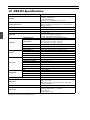
10
CBX-D3 Specifications
................ 20
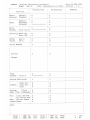
MIDI Implementation Chart
(on the page following the German section of
this manual)

Introduction1Introduction1Introduction 1
1 Introduction
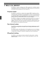
Welcome to the CBX-D3
Thank you for purchasing a CBX-D3 Digital Recording Processor. Connecting the
CBX-D3 to a controlling computer with supporting software and a SCSI hard disk will
provide up to four channels of CD quality audio recording, processing, and playback.
CBX-D3 features
• Four-channel system: 2-channel simultaneous recording, 4-channel playback
• A/D conversion: 16-bit linear
∆ Σ
modulation
• D/A conversion: 18-bit with oversampling digital filter
• Sampling frequencies: 48kHz, 44.1kHz, 32kHz, 22.05kHz
• Two analog inputs (two LINE jacks, two MIC jacks); four analog outputs. The analog
input level automatically switches to accommodate line or microphone input.
• One CD/DAT digital output
• Available recording time is limited only by hard disk capacity.
You can increase the recording time by installing larger disks or increasing the number
of disks.
• All audio data processing is carried out within the CBX-D3, so much less is demanded
of the computer, eliminating data bottlenecks and slow screen redraws.
• The system can be easily upgraded by loading the appropriate files. No ROM change
is required.
Important Notice
YAMAHA AND THE SOFTWARE COMPANIES THAT PRODUCE CBX-D3
CONTROLLING SOFTWARE CANNOT BE HELD RESPONSIBLE FOR ANY LOSS
OF DATA OR FOR ANY DIRECT, INDIRECT, SPECIAL INCIDENTAL,
CONSEQUENTIAL OR OTHER DAMAGES SUFFERED BY THE USER OR OTHERS
RESULTING FROM THE USE OR PURCHASE OF THE CBX-D3, ITS
DOCUMENTATION, OR SUPPORTING SOFTWARE.

2 Chapter 1 : Introduction2 Chapter 1 : Introduction2 Chapter 1 : Introduction
Unpacking
The CBX-D3 package should contain the following items.
Retain the packing materials for future use.
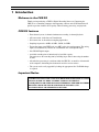
Installation
The CBX-D3 comes equipped with mounting brackets at both sides, allowing easy
installation on any standard 19" electronic equipment rack. (The unit requires 1U of rack
space.)
If you need to remove the mounting brackets, simply remove the three screws holding each
bracket in place. Be sure to reuse the same screws when reattaching the brackets; use of a
different screw size can cause internal damage.
Trademarks
Macintosh is a registered trademark of Apple Computer, Inc.
All other trademarks are the property of their respective holders.
Powering up a CBX-D3 System
Some computers are particular about the order in which devices are powered up. It is
generally best to switch on all peripheral SCSI devices before turning on the computer.
Downloading the System Software
Immediately following power-on, the CBX-D3 must download system data from the
computer. The 48kHz LED blinks to indicate that download is not yet completed.
CBX-D3 applications perform the download automatically. If you are working with a
CBX-D5 application, you will need to run the download yourself using a “System
Downloader” program, available on request from your Yamaha CBX-D3 dealer.
1 CBX-D3 Serial No:
1 PA-5B AC Adaptor (or recommended equivalent)
2 1U rack mounting brackets (attached to the CBX-D3)
1 Owner’s Manual
1 User Registration Card
NOTE:
To avoid system crash and data loss, NEVER switch off or disconnect any of
the SCSI devices while the CBX-D3 system is running.
NOTE:
Consult your Yamaha CBX-D3 dealer for information about the latest
CBX-D3 applications.
POWER
SON/TOFF
PHONES VOLUME
DIGITAL RECORDING PROCESSOR CBX-D3 SAMPLING FREQ 1 INPUT LEVEL 2
SCSI MIDI 48 44.1 32 22.05
OUTPUT MONITOR INPUT LEVEL
1234
CLIP
-6
-24
1 2
1 MIC 2
3 screws
3 screws

CBX-D3 Terminology3CBX-D3 Terminology3CBX-D3 Terminology 3
2 CBX-D3 Terminology
SCSI
SCSI (pronounced “scuzzy”) stands for Small Computer System Interface. The SCSI is a
standard format for connecting a computer to peripheral devices such as hard disks,
printers, and scanners. Devices are connected in a daisy chain, with each device (including
the computer) identified by a SCSI ID between 0 and 7.
Your CBX-D3, your computer, and your hard disk are connected together in a SCSI daisy
chain. The CBX-D3 uses the SCSI connection to transmit audio data to or from the hard
disk for recording or playback. The computer uses the connection to send control data to
the CBX-D3, and to perform copy, delete, and backup operations on the hard disk. With
appropriate software, it is also possible to transfer digital audio data directly to your
computer for onscreen waveform editing or other processing.
Although the SCSI standard is fairly robust, some care must be taken when connecting and
setting up the devices. For details about how to connect hard disk drives, refer to page 10.
Sound files
Just like other types of computer data, digital audio data is stored in files — sound files.
When recording starts, a sound file is created on the hard disk. Sound files can be named,
copied, or deleted just like any other computer files.
Sampling frequency
During the analog to digital conversion process, the level of the analog audio signal is
sampled (measured) many times per second.
Each of these sample measurements is then stored as a 16-bit binary value. For digital to
analog conversion (playback), these 16-bit binary values are used to reconstruct the analog
audio signal. The rate at which these sample measurements take place is called the
sampling frequency. CD players use a sampling frequency of 44.1kHz.
The CBX-D3 can record audio using any one of four sampling frequencies: 48kHz,
44.1kHz, 32kHz, and 22.05kHz. The audio quality (bandwidth) of a digital system is
directly affected by the sampling frequency. Essentially, the audio bandwidth will be
roughly half the chosen sampling frequency. Refer to the discussion of sampling frequency
in the chapter on “Recording” (see page 16) for additional details.

4 Chapter 3 : What is the CBX-D3?4 Chapter 3 : What is the CBX-D3?4 Chapter 3 : What is the CBX-D3?
3 What is the CBX-D3?
The CBX-D3 is a digital recording processor. When connected to a controlling computer
with supporting software and a SCSI hard disk, the CBX-D3 provides up to four channels
of CD-quality audio recording, processing, and playback.
Computer based
The CBX-D3 is controlled by a computer that is running CBX-D3 supporting software.
All audio data processing takes place inside the CBX-D3, so there is very little demand on
the controlling computer. For this reason the CBX-D3 can be used even with relatively less
powerful, inexpensive computers. The CBX-D3 leaves the computer free to get on with
other jobs such as processing of MIDI sequence data and screen updates.
The CBX-D3 is connected to your computer and hard disk by SCSI. It is also connected
to the computer by MIDI cables. The SCSI connection supplies control data from the
computer, and transfers audio data to or from the hard disk for recording or playback. The
MIDI connection carries real-time volume data, synchronization clock, playback speed
data, and playback and recording start/stop signals.
Four-channel system
The CBX-D3 is a four-channel system, providing two channels of simultaneous recording
and four channels of playback. Two channels can be recording while the other two are
playing back.
The CBX-D3 requires about 100 megabytes of free hard-disk space to record 10 minutes
of stereo digital audio at a sampling frequency of 44.1kHz. You can increase the available
recording time by changing to a larger disk or adding more disks to the SCSI chain.
CD quality & editing
The CBX-D3 records audio data in 16-bit resolution. Recording quality at sampling
frequencies of 44.1 and 48kHz is at CD level, with true reproduction, low noise, and
minimal distortion.

The CBX-D3 in a MIDI recording system5The CBX-D3 in a MIDI recording system5The CBX-D3 in a MIDI recording system 5
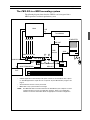
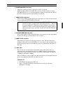
The CBX-D3 in a MIDI recording system
The following diagram shows how the CBX-D3 can be integrated into a
MIDI-sequencer-based music production system
.
DAT
Mixer
Tone Module
MIDI
Interface
HARD
DISK
MIC
MIDI OUT
DIGITAL
OUT
ANALOG IN X 2
MIDI IN
MIDI OUT
MIDI
IN
MIDI
OUT
MIDI
OUT
MIDI
IN
MIDI IN
SCSI
(Dedicated cable)
COMPUTER
CBX-D3
LINE IN X 4
ANALOG OUT X 4
LINE
IN
SCSI
SCSI TERMINATOR
* CBX-D3 applications automatically load system software to the CBX-D3 at time of power
on. CBX-D5 applications require the use of separate “System Downloader” program. See
page 2.
* SCSI terminator must be correctly connected.
* MIDI cables carry system-exclusive messages.
NOTE: The MIDI and SCSI connections between the CBX-D3 and your computer can have
a significant impact on how your application functions. Refer to your application
software’s manual for information about the appropriate connection configuration.

6 Chapter 4 : Controls & Connections6 Chapter 4 : Controls & Connections6 Chapter 4 : Controls & Connections
4 Controls & Connections
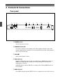
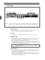
Front panel
1
POWER switch
Switches the power on or off.
2
PHONES connection
A 1/4-inch (6.35mm) stereo headphone jack. The headphones monitor all four audio
channels simultaneously: channels 1 and 3 are heard in the left speaker, while channels 2
and 4 are heard in the right.
3
VOLUME
Adjusts the headphone volume.
4
SCSI indicator
Red/green LED indicator showing the current SCSI status. GREEN indicates that the
CBX-D3 is reading from disk, sending or receiving commands over the SCSI, or
downloading system data.
Solid RED indicates that the CBX-D3 is recording to disk. Flashing RED indicates an
error condition.
5
MIDI indicator
Green LED. Lights up when the CBX-D3 receives a supported system-exclusive message.
POWER
SON/TOFF
PHONES VOLUME
DIGITAL RECORDING PROCESSOR CBX-D3 SAMPLING FREQ 1 INPUT LEVEL 2
SCSI MIDI 48 44.1 32 22.05
OUTPUT MONITOR INPUT LEVEL
1234
CLIP
-6
-24
1 2
1 MIC 2
1 4 6 7 8 9 0
5
2 3

Front panel7Front panel7Front panel 7
6
SAMPLING FREQ indicators
Indicate the sampling frequency selected for recording or playback:
48kHz, 44.1kHz, 32kHz, or 22.05kHz. The frequency selection is made by software.
The 48kHz LED also acts as a download indicator, flashing to indicate that the CBX-D3
has not yet completed power-on downloading of system data.
7
INPUT LEVEL indicators
Two 3-segment LED bargraphs indicating the audio input levels. You can adjust the input
levels by turning the INPUT LEVEL control dials.
8
OUTPUT MONITOR indicators
Four variable-brightness LEDs. Each LED indicates the output level of the corresponding
channel. The LED gets gradually brighter as the level rises.
9
INPUT LEVEL controls
Independent level controls for analog input channels 1 and 2. You can also use these
controls to balance the left and right channels of a stereo source connected to the analog
inputs. Note that the input level automatically changes to accommodate microphone or
line input.
0
MIC 1 & 2
Two 1/4-inch jacks for direct input of microphone analog audio signals. These are
unbalanced inputs with nominal input levels of –60dBm. Plugging a microphone into
either of these jacks automatically switches the channel’s nominal input level from line
(–20dBm) to microphone (–60dBm).
Note that connecting a cable to a MIC jack automatically disables any line input connected
to the corresponding ANALOG IN jack on the near panel.
IMPORTANT:
1. NEVER plug a line input into a MIC jack.
2. Always set the INPUT LEVEL to minimum before inserting or removing a
microphone or line input.
NOTE:
The top LED in each of the bargraphs is the “CLIP” LED. While peak
indicators on analog equipment tend to light up approximately 3 ~ 6dB below
the signal clipping level, CLIP LEDs on digital equipment come on only if
clipping has actually occurred. Since digital-audio signal clipping produces
unpleasant distortion, pops, and clicks, you DO NOT want the CLIP LEDs to
come on.

8 Chapter 4 : Controls & Connections8 Chapter 4 : Controls & Connections8 Chapter 4 : Controls & Connections
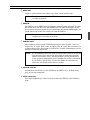
Rear panel
1
DC IN connector
Power connector. Connect one end of the supplied power-adaptor cord to this connector,
then insert the plug end of the cord into an appropriate AC receptacle.
2
Cable clip
Wrap the adaptor cord around this clip to help prevent accidental disconnection.
3
ANALOG IN 1&2
Two 1/4-inch phone jacks for direct input of analog audio signals. These are unbalanced
inputs with nominal input levels of –20dBm, and can be connected to the outputs of a
mixer, synthesizer, drum machine, or other such device.
Note that connecting a cable to the MIC jack on the front panel automatically disables the
corresponding ANALOG IN jack. If cables are connected to both MIC and ANALOG IN,
only the MIC (nominal –60dBm) signals will be received.
4
ANALOG OUT 1~4
Four 1/4-inch phone jacks that output audio data in analog form. These are unbalanced
output jacks with a nominal output level of –20dBm. You can connect these to a mixer,
amplifier, tape recorder, or DAT recorder.
If you connect a line to OUT1 only, the OUT1 jack will output audio signals for all four
channels. If you connect to OUT1 and OUT2 only, then OUT1 will output channels 1 and
3, while OUT2 will output channels 2 and 4.
NOTE:
Always set the INPUT LEVEL to minimum before inserting or removing a
microphone or line input.
NOTE: For your convenience, the top panel includes illustrations and names of all terminals located on the
rear panel. This may help you locate cables and connectors without having to look behind the device.
SCSI
SCSI ID
DIGITAL
OUT
MIDI
IN
OUT
OUT 1OUT 2OUT 4IN 1IN 2 OUT 3
DC IN
ANALOG IN/OUT
2 3 4 9
1 5 6 7 8
5

Rear panel9Rear panel9Rear panel 9
5
MIDI OUT
Outputs a synchronization clock and messages about various internal events.
6
MIDI IN
The CBX-D3 receives MIDI control data from the computer via this connection. To ensure
that control data is not delayed by other MIDI devices, the CBX-D3 should be the first
device connected to your computer. If your computer provides multiple MIDI outputs, you
should dedicate one of these for exclusive use with the CBX-D3.
7
DIGITAL OUT
A RCA (phono) jack that outputs CD/DAT-format digital audio. Channels 1 and 3 are
output as the “L” signal, while 2 and 4 are output as the “R” signal. This jack allows you
to connect directly to the digital input of a DAT or DCC recorder, eliminating the need for
multiple D/A and A/D conversions.
8
SCSI ID selector
A thumbwheel switch used to set the SCSI ID for the CBX-D3. See “SCSI ID setting”
(page 12) for more information.
9
SCSI connectors
Two 50-pin Amphenol type connectors used to connect the CBX-D3 to the SCSI daisy
chain.
NOTE:
Be sure to connect this to the MIDI IN terminal of your computer prior to
recording or playback.
NOTE:
Be sure to connect the MIDI IN terminal to the MIDI OUT terminal of your
computer prior to recording or playback.
NOTE:
It is well known that the weakest links in a digital audio system are the A/D and
D/A converters. Once converted to digital form, the audio signal becomes
immune to distortions, noises, and other problems generally introduced by
analog equipment. Although the effect of multiple conversions is rather subtle,
it is nevertheless good practice to reduce the number of conversions and
transfer the data in digital form wherever possible.

10 Chapter 5 : Connecting Hard Disk Drives10 Chapter 5 : Connecting Hard Disk Drives10 Chapter 5 : Connecting Hard Disk Drives
5 Connecting Hard Disk Drives
Before connecting a hard disk drive, read through this chapter to familiarize yourself with
SCSI and how a SCSI daisy chain should be set up.
What type of hard disk?
If you don’t already have a hard disk or are thinking of buying a larger one, please consult
your Yamaha CBX-D3 dealer for recommendations.
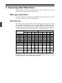
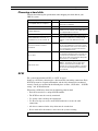
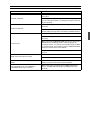
Hard disk size
The following table shows approximate available recording times for various sizes of hard
disk. Available recording times are shown for all of the CBX-D3’s sampling frequencies.
As you can see, time capacity decreases as sampling frequency goes up. This is because
the higher frequencies generate much more digital data, and therefore require much more
space. For details about frequency selection, refer to “Sampling Frequency” on page 16.
Although it is doubtful that you will ever buy a hard disk smaller than 40MB for use with
the CBX-D3, the values below 40MB will be useful for checking the remaining recording
time on a hard disk that already contains some sound files.
Hard disk / Max.
Sound File Size
Stereo Recording (minutes) Mono Recording (minutes)
22.05
kHz
32
kHz
44.1
kHz
48
kHz
22.05
kHz
32
kHz
44.1
kHz
48
kHz
2000MB (2GB) 380 260 190 174 760 520 380 348
1000MB (1GB) 190 130 95 87 380 260 190 174
660MB 124 85 62 57 248 170 124 114
330MB 62 42 31 28 124 84 62 56
200MB 40 25 20 17 80 50 40 34
100MB 20 13 10 8 40 26 20 16
40MB 8 5 4 3.30 16 10 8 7
20MB 4 3 2 1.42 8 6 4 3.24
10MB 2 1.18 1 51
secs
4 2.36 2 1.42
5MB 1 38
secs
30
secs
26
secs
2 1.16 1 52
secs
1MB 12
secs
7 secs 6 secs 5 secs 24
secs
14
secs
12
secs
10
secs

Choosing a hard disk11Choosing a hard disk11Choosing a hard disk 11
Choosing a hard disk
Consider the following disk specifications when shopping for a hard disk for your
CBX-D3 system.
SCSI
For a general introduction to SCSI, see “SCSI” on page 3.
Setting up a SCSI daisy chain involves a little more than just making connections. Each
SCSI device must be assigned an ID number, and the daisy chain must be terminated
correctly. Details are explained in the following three sections, “SCSI cables,” “SCSI ID
setting,” and “SCSI termination.”
When using a SCSI daisy chain, bear the following points in mind.
• Each device must have a unique SCSI ID number.
• The SCSI bus must be correctly terminated.
• Use quality cables and keep the length down.
• Use the wire clips (or screws) on the SCSI connectors to secure the cable
connections.
• All devices connected in the daisy chain must be switched on.
• Never switch off or disconnect a device once the system is running.
Specification Check Notes
Is it compatible with your computer?
It may be advertised as compatible, or your
dealer may recommend it.
Does it have two SCSI connectors? You need two to continue the SCSI daisy chain.
Are the SCSI connectors 25-pin D-SUB
or 50-pin Amphenol?
Macintosh computers are fitted with a 25-pin
D-SUB connector, while most other SCSI devices
use a 50-pin Amphenol connector.
Are the SCSI cables supplied? If not, you will need to purchase these separately.
Can the SCSI ID be set from 0 ~ 7?
(For Macintosh, you only need 0 ~ 6)
If not, it might clash with another device's ID, in
which case you may have to rearrange the ID
numbers of some other SCSI devices in the
chain.
Does it have internal or external
termination?
External terminators are normally connected to
the rear of the SCSI device. If the device has an
internal terminator, make sure it can be switched
off so that any device can be positioned at the
end of the SCSI daisy chain.
Access time?
Measured in milliseconds, this is an indication of
how fast data from different areas of the disk can
be retrieved. The maximum we recommend is
30ms. Access times slower than this will degrade
the performance of the CBX-D3.
Data transfer rate?
Usually measured in megabytes per second
(MB/sec), this indicates how fast data can be
written to and read from the hard disk. The
minimum we recommend is 1MB/sec. A transfer
rate less than this will degrade the performance
of the CBX-D3.
NOTE:
Switch off all your equipment before making any SCSI connections.

12 Chapter 5 : Connecting Hard Disk Drives12 Chapter 5 : Connecting Hard Disk Drives12 Chapter 5 : Connecting Hard Disk Drives
SCSI cables
Cable length should be kept low. The total length of the SCSI daisy chain must not exceed
6m (20ft).
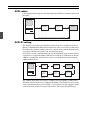
SCSI ID setting
The SCSI bus is a parallel type connection, and data on the bus is available to all devices.
However, communication will be between two devices only, so each device is allocated an
ID number, like an address number. In this way, only the device with the ID number that
is specified in the data will actually read and respond to the data.
If two devices share the same ID number, the system will probably crash, so make sure that
each device has a unique ID number. SCSI devices usually have a DIP switch or, like the
CBX-D3, a thumbwheel switch that you can use to set the ID. Refer to the instructions
supplied with the device.
The example above shows seven devices (computer and six peripherals) connected in a
SCSI daisy chain. Each device has a different ID number. Note that the last device in the
chain is terminated. In most cases SCSI ID 7 is reserved for use by the computer, and ID
0 for the internal hard disk. Do not use either of these IDs for any other SCSI device.
HARD DISK
1
CBX-D3HARD DISK
2
SCSI SCSISCSI
Total length of SCSI daisy chain must not exceed 6m (20ft)
HARD DISK
1
CBX-D3HARD DISK
2
SCSI SCSISCSI
ID No. 1 ID No. 2 ID No. 3
HARD DISK
3
SCSI
SCSI
DEVICE
SCSI
ID No. 4ID No. 5
SCSI
DEVICE
SCSI
ID No. 6
This device is
terminated

SCSI termination13SCSI termination13SCSI termination 13
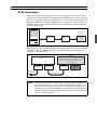
SCSI termination
Unlike audio signals, digital signals only have two values: high and low (+5V and 0V).
When no data is being transmitted, it is important that SCSI bus lines are kept in the high
state (+5V), so that when data is transmitted there is a clear distinction between high and
low pulses and the data is transferred without error. To achieve this, a device known as a
SCSI terminator is connected in the SCSI daisy chain. A terminator is usually fitted to the
last device in the chain.
Some SCSI devices have a built-in terminator, and must therefore be connected at the end
of the daisy chain. The CBX-D3 and many other devices utilize a detachable in-line
terminator, as illustrated below.
NOTE:
If the SCSI daisy chain is not terminated correctly, numerous problems
including data corruption, system crashes, and intermittent glitches can
occur. If you have just set up your SCSI daisy chain or have added a new
SCSI device to it and it is not working as it should, check that the SCSI daisy
chain is terminated correctly. If the problem persists, try connecting the SCSI
devices in a different order.
Terminate
this device
HARD DISK
1
CBX-D3HARD DISK
2
SCSI SCSISCSI
To the next
SCSI device
CBX-D3
(In this case the CBX-D3 is the last device connected
in the daisy chain, so the SCSI terminator is
connected as shown)
SCSI PLUG SCSI
TERMINATOR
HARD DISK 2
SCSI PLUGSCSI PLUG
SCSI CABLE

14 Chapter 6 : Working with Hard Disks14 Chapter 6 : Working with Hard Disks14 Chapter 6 : Working with Hard Disks
6 Working with Hard Disks
After connecting your hard disk, setting the SCSI ID, and installing the SCSI terminator,
you will need to format the hard disk before it can be used. The system will not recognize
an unformatted hard disk.
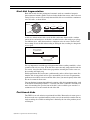
Formatting
Most SCSI hard disks are supplied with their own disk-formatting software. Please format
the disk according to directions given in the hard disk’s operating manual.
The formatting program will probably ask you to specify the disk’s SCSI ID number. This
is the ID number that you set using the thumbwheel or DIP switch on the hard disk unit.
You may also be asked to set the interleave value; if so, refer to the hard disk’s operating
manual for the appropriate response. Also check your computer’s manual for additional
information about connection of SCSI disk drives.
File management and backup
Once you have stored sound files to disk, you can copy, delete, or size-check them using
the same commands that you use for your other computer files.
You can also back them up using conventional data compression and backup utilities.
However, due to the relatively large size of sound files, floppy disks are not the most
effective backup media. Removable hard disks and magneto-optical disks are well suited
to this task; commonly available sizes include 88MB, 128MB, and 650MB.
Another backup option is to digitally transfer your sound files to a DAT recorder. You can
then record them back to the CBX-D3 if the need arises.
Computer utilities
There are many computer utilities available for managing files and hard disks. Disk
defragmentation utilities are particularly useful, as described below. File compression
utilities, which increase the apparent disk capacity by compressing your files, are a
different matter. We recommend that you either avoid these or use them with extreme care,
as some of these utilities are incompatible with the CBX-D3 and may effectively destroy
your sound files.
A página está carregando...
A página está carregando...
A página está carregando...
A página está carregando...
A página está carregando...
A página está carregando...
A página está carregando...
A página está carregando...
A página está carregando...
-
 1
1
-
 2
2
-
 3
3
-
 4
4
-
 5
5
-
 6
6
-
 7
7
-
 8
8
-
 9
9
-
 10
10
-
 11
11
-
 12
12
-
 13
13
-
 14
14
-
 15
15
-
 16
16
-
 17
17
-
 18
18
-
 19
19
-
 20
20
-
 21
21
-
 22
22
-
 23
23
-
 24
24
-
 25
25
-
 26
26
-
 27
27
-
 28
28
-
 29
29


Yamaha CBX-D3 Manual do proprietário
- Categoria
- Equipamento musical
- Tipo
- Manual do proprietário
em outras línguas
- español: Yamaha CBX-D3 El manual del propietario
- français: Yamaha CBX-D3 Le manuel du propriétaire
- italiano: Yamaha CBX-D3 Manuale del proprietario
- English: Yamaha CBX-D3 Owner's manual
- русский: Yamaha CBX-D3 Инструкция по применению
- Nederlands: Yamaha CBX-D3 de handleiding
- Deutsch: Yamaha CBX-D3 Bedienungsanleitung
- dansk: Yamaha CBX-D3 Brugervejledning
- čeština: Yamaha CBX-D3 Návod k obsluze
- svenska: Yamaha CBX-D3 Bruksanvisning
- polski: Yamaha CBX-D3 Instrukcja obsługi
- Türkçe: Yamaha CBX-D3 El kitabı
- suomi: Yamaha CBX-D3 Omistajan opas
- română: Yamaha CBX-D3 Manualul proprietarului