Ariston PK 640 R L GH AG Guia de usuario
- Categoria
- Fogões
- Tipo
- Guia de usuario
Este manual também é adequado para

GB
1
HOB
PK 741 RQO GH AG
PK 750 RL GH AG
PK 640 RL GH AG
PK 760 RF GH AG
Contents
Installation, 2-6
Positioning
Electrical connection
Gas connection
Data plate
Burner and nozzle specifications
Description of the appliance, 7
Overall view
Start-up and use, 8-10
Practical advice on using the burners
Practical advice on using the the Ceramic Glass
Module
Precautions and tips, 11
General safety
Disposal
Maintenance and care, 12
Switching the appliance off
Cleaning the appliance
Gas tap maintenance
Troubleshooting, 13
Operating Instructions
Español, 14
Português, 29
English,1
ES
PT
GB

GB
2
! Before operating your new appliance please read this
instruction booklet carefully. It contains important
information for safe use, installation and care of the
appliance.
! Please keep these operating instructions for future
reference. Pass them on to possible new owners of the
appliance.
Positioning
! Keep packaging material out of the reach of children. It
can become a choking or suffocation hazard (see
Precautions and tips).
! The appliance must be installed by a qualified
professional according to the instructions provided.
Incorrect installation may cause harm to people and
animals or may damage property.
! This unit may be installed and used only in permanently
ventilated rooms in accordance with British Standard
Codes Of Practice: B.S. 6172 / B.S. 5440, Par. 2 and B.S.
6891 Current Editions. The following requirements must be
observed:
• The room must be equipped with an air extraction
system that expels any combustion fumes. This may
consist of a hood or an electric fan that automatically
starts each time the appliance is switched on.
• The room must also allow proper air circulation, as air is
needed for combustion to occur normally. The flow of
air must not be less than 2 m
3
/h
per kW of installed power.
The air circulation system may
take air directly from the outside
by means of a pipe with an inner
cross section of at least 100
cm
2
; the opening must not be
vulnerable to any type of
blockages.
The system can also provide the
air needed for combustion
indirectly, i.e. from adjacent
rooms fitted with air circulation
tubes as described above.
However, these rooms must not
be communal rooms, bedrooms
or rooms that may present a fire hazard.
• Liquid petroleum gas sinks to the floor as it is heavier
than air. Therefore, rooms containing LPG cylinders
must also be equipped with vents to allow gas to
escape in the event of a leak. As a result LPG
cylinders, whether partially or completely full, must not
be installed or stored in rooms or storage areas that are
below ground level (cellars, etc.). It is advisable to
keep only the cylinder being used in the room,
positioned so that it is not subject to heat produced by
external sources (ovens, fireplaces, stoves, etc. ) which
could raise the temperature of the cylinder above 50°C.
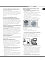
Fitting the appliance
Gas and mixed hobs are manufactured with type X
degree protection against overheating. The following
precautions must be taken when installing the hob:
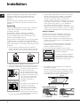
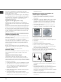
• Kitchen cabinets adjacent to the appliance and taller
than the top of the hob must be at least 600 mm from
the edge of the hob.
• Hoods must be installed according to their relative
installation instruction manuals and at a minimum
distance of 650 mm from the hob.
• Place the wall cabinets adjacent to the hood at a
minimum height of 420 mm from
the hob (see figure).
If the hob is installed beneath a
wall cabinet, the latter must be
situated at a minimum of 700 mm
above the hob (see figure).
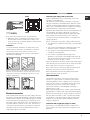
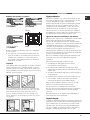
• The installation cavity should have the dimensions
indicated in the figure.
Fastening hooks are provided, allowing you to fasten
the hob to tops that are between 20 and 40 mm thick.
To ensure the hob is securely fastened to the top, we
recommend you use all the hooks provided.
555 mm
55 mm
475 mm
Hook fastening diagram
Hooking position Hooking position
for top H=20 mm for top H=30 mm
Installation
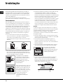
Enlarging the ventilation slot
between window and floor.
Adjacent
Room
Room to be
Vented
A
Examples of ventilation holes
for comburant air.
In a chimney stack or branched flue.
(exclusively for cooking appliances)
Directly to
the Outside
600mm min.
600mm min.
700mm min.

GB
3
Front
Hooking position Back
for top H=40 mm
! Use the hooks contained in the “accessory pack”
• Where the hob is not installed over a built-in oven, a
wooden panel must be installed as insulation. This
must be placed at a minimum distance of 20 mm from
the lower part of the hob.
Ventilation
To ensure adequate ventilation, the back panel of the
cabinet must be removed. It is advisable to install the
oven so that it rests on two strips of wood, or on a
completely flat surface with an opening of at least 45 x
560 mm (see diagrams).
When installing the cooktop above a built-in oven
without forced ventilation, ensure that there are air
inlets and outlets for ventilating the interior of the
cabinet adequately.
Electrical connection
Hobs equipped with a three-pole power supply cable are
designed to operate with alternating current at the voltage
and frequency indicated on the data plate (this is located
on the lower part of the appliance). The earth wire in the
cable has a green and yellow cover. If the appliance is to
be installed above a built-in electric oven, the electrical
connection of the hob and the oven must be carried out
separately, both for electrical safety purposes and to
make extracting the oven easier.
Connecting the supply cable to the mains
Install a standardised plug corresponding to the load
indicated on the data plate.
The appliance must be directly connected to the mains
using an omnipolar circuit-breaker with a minimum contact
opening of 3 mm installed between the appliance and the
mains. The circuit-breaker must be suitable for the charge
indicated and must comply with current electrical
regulations (the earthing wire must not be interrupted by the
circuit-breaker). The supply cable must not come into
contact with surfaces with temperatures higher than 50°C.
! The installer must ensure that the correct electrical
connection has been made and that it is compliant with
safety regulations.
Before connecting to the power supply, make sure that:
• The appliance is earthed and the plug is compliant with
the law.
• The socket can withstand the maximum power of the
appliance, which is indicated on the data plate.
• The voltage is in the range between the values
indicated on the data plate.
• The socket is compatible with the plug of the
appliance. If the socket is incompatible with the plug,
ask an authorised technician to replace it. Do not use
extension cords or multiple sockets.
! Once the appliance has been installed, the power supply
cable and the electrical socket must be easily accessible.
! The cable must not be bent or compressed.
! The cable must be checked regularly and replaced by
authorised technicians only (see Assistance).
! The manufacturer declines any liability should these
safety measures not be observed.
Gas connection
The appliance should be connected to the main gas
supply or to a gas cylinder in compliance with current
national regulations. Before carrying out the connection,
make sure the cooker is compatible with the gas supply
you wish to use. If this is not the case, follow the
instructions indicated in the paragraph “Adapting to
different types of gas.”
When using liquid gas from a cylinder, install a pressure
regulator which complies with current national regulations.
! Check that the pressure of the gas supply is consistent
with the values indicated in Table 1 (“Burner and nozzle
specifications”). This will ensure the safe operation and
longevity of your appliance while maintaining efficient
energy consumption.
Connection with a rigid pipe (copper or steel)
! Connection to the gas system must be carried out in
such a way as not to place any strain of any kind on the
appliance.
560 mm
.
4
5
m
m
.

GB
4
There is an adjustable L-shaped pipe fitting on the
appliance supply ramp and this is fitted with a seal in
order to prevent leaks. The seal must always be replaced
after rotating the pipe fitting (seal provided with
appliance). The gas supply pipe fitting is a threaded 1/2
gas cylindrical male attachment.
Connecting a flexible jointless stainless steel pipe to a
threaded attachment
The gas supply pipe fitting is a threaded 1/2 gas
cylindrical male attachment.
These pipes must be installed so that they are never
longer than 2000 mm when fully extended. Once
connection has been carried out, make sure that the
flexible metal pipe does not touch any moving parts and
is not compressed.
! Only use pipes and seals that comply with current
national regulations.
Checking the tightness of the connection
! When the installation process is complete, check the
pipe fittings for leaks using a soapy solution. Never use a
flame.
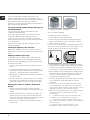
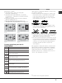
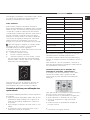
Adapting to different types of gas
To adapt the hob to a different type of gas other than
default type (indicated on the rating plate at the base of
the hob or on the packaging), the burner nozzles should
be replaced as follows:
1. Remove the hob grids and slide the burners off their
seats.
2. Unscrew the nozzles using a 7 mm socket spanner,
and replace them with nozzles for the new type of gas
(see table 1 “Burner and nozzle characteristics”).
3. Reassemble the parts following the above procedure in
the reverse order.
4. Once this procedure is finished, replace the old rating
sticker with one indicating the new type of gas used.
Sticker are available from any of our Service Centres.
Replacing the nozzles on separate “double flame “
burners:
1. remove the grids and slide the burners from their
housings. The burner consists of 2 separate parts (see
figure);
2. unscrew the burers with a 7 mm wrench spanner. The
internal burner has a nozzle, the external burner has
two (of the same size). Replace the nozzle with models
suited to the new type of gas (see table 1).
3. replace all the components by repeating the steps in
reverse order.
• Adjusting the burners’ primary air :
Does not require adjusting.
• Setting the burners to minimum:
1. Turn the tap to the low flame position.
2. Remove the knob and adjust the adjustment screw,
which is positioned in or next to the tap pin, until the
flame is small but steady.
! In the event of single-control DRDA (DCDR) burners,
adjustment can be performed by intervening on the 2
screws located near the tap pin (see picture).
3. Having adjusted the flame to the required low setting,
while the burner is alight, quickly change the position of
the knob from minimum to maximum and vice versa
several times, checking that the flame does not go out.
4. Some appliances have a safety device (thermocouple)
fitted. If the device fails to work when the burners are
set to the low flame setting, increase this low flame
setting using the adjusting screw.
5. Once the adjustment has been made, replace the seals
on the by-passes using sealing wax or a similar
substance.
6. In the event of discrete-adjustment knobs with
LED visualisation, turn the knob to the minimum
power setting them remove it and intervene on the
adjustment screw located near the tap pin.
7. Minimum setting adjustment of the DRDA (DCDR)
burner with discrete adjustment and LED
visualisation:
• To adjust the outer ring, turn the knob anti-
clockwise to the minimum power position.
• To adjust the minimum power setting of the
inner ring, turn the knob clockwise to the minimum
power position.
• Remove the knob and intervene on the
adjustment screw located near the tap pin.
Inner DRDA (DCDR)
burner adjustment
Total DRDA
(DCDR) burner
adjustment

GB
5
! If the appliance is connected to liquid gas, the regulation
screw must be fastened as tightly as possible.
! Once this procedure is finished, replace the old rating
sticker with one indicating the new type of gas used.
Stickers are available from any of our Service Centres.
! Should the gas pressure used be different (or vary
slightly) from the recommended pressure, a suitable
pressure regulator must be fitted to the inlet pipe (in order
to comply with current national regulations).
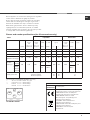
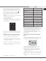
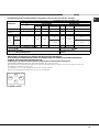
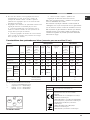
PK 640 RL GH AG
RR
DC
S
A
Table 1 Liquid Gas Natural Gas
Burner Diameter Thermal Thermal By-pass Nozzle Flow* Thermal Nozzle Flow*
power power 1/100 1/100 (g/h) power 1/100 (l/h)
kW kW kW
(p.c.s.*) (p.c.s.*) (p.c.s.*)
(mm) Reduced Nominal (mm) (mm) *** ** Nominal (mm)
Supply pressures
Nominal (mbar)
Minimum (mbar)
Maximum (mbar)
28-30
20
35
37
25
45
20
17
25
Reduced Fast (RR)
Semi Fast (S)
Auxiliary (A)
100
75
55
0.70
0.40
0.40
2.60
1.65
1.00
39
28
28
80
64
50
189
120
73
186
118
71
2.60
1.65
1.00
122 (H)
96 (Y)
79 (6)
248
157
95
Double flame
(DCDR internal) (1)
30 0,30 0,90 27 44 65 64 0,90 74 86
Double
flame (1)
(DCDR
internal)
(DCDR
external
2 nozzle)
130 1,50 3,60
27 44
262 257 3,60
74
343
55 60x2 100x 2
Burner and nozzle specifications (for 60 cm versions only)
(1) For single-control DRDA (DCDR) burner only
* At 15°C and 1013 mbar - dry gas
** Propane P.C.S. = 50.37 MJ/Kg
*** Butane P.C.S. = 49.47 MJ/Kg
Natural P.C.S. = 37.78 MJ/m³
Electrical
connections
DATA PLATE
see data plate
This appliance conforms to the following
European Economic Community directives:
- 2006/95/EEC dated 12/12/06 (Low
Voltage) and subsequent amendments
- 2004/108/EEC dated 15/12/04
(Electromagnetic Compatibility) and
subsequent amendments
- 93/68/EEC dated 22/07/93 and
subsequent amendments.
- 2009/142/EEC dated 30/11/09 (Gas) and
subsequent amendments.
- 2002/96/EC and subsequent
amendments.

GB
6
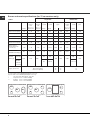
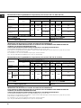
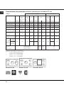
Table 1 Liquid Gas Natural Gas
Burner Diameter Thermal Thermal By-pass Nozzle Flow* Thermal Nozzle Flow*
power power 1/100 1/100 (g/h) power 1/100 (l/h)
kW kW kW
(p.c.s.*) (p.c.s.*) (p.c.s.*)
(mm) Reduced Nominal (mm) (mm) *** ** Nominal (mm)
Supply pressures
Nominal (mbar)
Minimum (mbar)
Maximum (mbar)
28-30
20
35
37
25
45
20
17
25
Reduced Fast (RR)
Semi Fast (S)
Auxiliary (A)
Semi-Fishburner (SP)
Double Flame
(DCDR Internal) (2)
Double Flame
(DCDR External)
2 nozzle (2)
100
75
55
—
30
130
0.70
0.40
0.40
0.70
0.40
1.50
2.60
1.65
1.00
1.50
0.90
4.10
39
28
28
39
28
61
80
64
50
60
44
70x2
189
120
73
109
65
298
186
118
71
107
64
293
2.60
1.65
1.00
1.50
0.90
4.10
122 (H)
96 (Y)
79 (6)
88
70
114x2
248
157
95
143
86
390
Double flame
(DCDR internal) (1)
30 0,30 0,90 27 44 65 64 0,90 69 86
Double
flame (1)
(DCDR
internal)
(DCDR
external
2 nozzle)
130 1,50 4,60
27 44
334 329 5,00
69
476
55 70 x 2 113 x 2
Burner and nozzle specifications (for 75 cm versions only)
(1) For single-control DRDA (DCDR) burner only
(2) For dual-control DRDA (DCDR) burner only
* At 15°C and 1013 mbar - dry gas
** Propane P.C.S. = 50.37 MJ/Kg
*** Butane P.C.S. = 49.47 MJ/Kg
Natural P.C.S. = 37.78 MJ/m³
PK741RQO GH AG
DC
S
A
PK750RL GH AG
RR
DC
S
S
A
PK760RF GH AG
RR
DC SP
A

GB
7
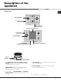
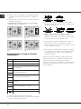
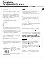
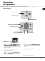
Description of the
appliance
Overall view
*
Only available on certain models.
• The INDICATOR LIGHT FOR CERAMIC GLASS
MODULE switches on whenever the selector knob
is moved from the ‘off’ position.
• GAS BURNERS differ in size and power. Use the
diameter of the cookware to choose the most
appropriate burner to cook with.
• Control Knobs for GAS BURNERS and CERAMIC
GLASS MODULE* adjust the power or the size of
the flame.
• GAS BURNER ignition* enables a specific burner
to be lit automatically.
• SAFETY DEVICE* stops the gas flow if the flame is
accidentally extinguished.
SAFETY
DEVICES *
Ignition for
GAS BURNERS *
Support Grid for
COOKWARE
CERAMIC GLASS MODULE *
Control Knobs for
GAS BURNERS and
CERAMIC GLASS MODULE*
Control Knobs for
GAS BURNERS
Indicator Light for
CERAMIC GLASS MODULE *
GAS BURNERS
GAS BURNERS
Support Grid for
COOKWARE

GB
8
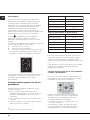
! The position of the corresponding gas burner or
electric hotplate* is shown on every knob.
Gas cooker hobs are equipped with discrete power
adjustment that allows for accurately adjusting the
flame to 5 different power levels. Thanks to this
system, gas hobs are also capable of guaranteeing
the same cooking results for each recipe, as the
optimal power level for the desired type of cooking
can be identified in an easier, more accurate way.
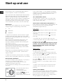
Gas burners
Each burner can be adjusted to one of the following
settings using the corresponding control knob:
• Off
Maximum
Minimum
To light one of the burners, hold a lit match or lighter
near the burner and, at the same time, press down
and turn the corresponding knob anti-clockwise to the
maximum setting.
Since the burner is fitted with a safety device, the
knob should be pressed for approximately 2-3
seconds to allow the automatic device keeping the
flame alight to heat up.
When using models with an ignition button, light the
desired burner pressing down the corresponding
knob as far as possible and turning it anticlockwise
towards the maximum setting.
! If a flame is accidentally extinguished, turn off the
control knob and wait for at least 1 minute before
trying to relight it.
To switch off the burner, turn the knob in a clockwise
direction until it stops (when reaches the “•” position).
Discrete flame adjustment
The selected burner can be adjusted - by means of
the knob - to 5 different power levels.
To shift between levels, simply turn the knob
towards the desired power level.
A click signals the passage from one power level to
the other.
The selected power level is
indicated by the
corresponding symbol
(symbols
) and, on
hobs equipped with a
display, by the LEDs that turn
on (5 = max. power; 1 = min. power). The system
guarantees accurate flame adjustment and uniform
cooking results by facilitating selection of the
desired power level.
The "double-flame" burner
This gas burner consists of two concentric flame
rings that can operate jointly or independently (in
case of dual-control only).
As the burner is fitted with a safety device, the
knob should be pressed down for approximately 2-3
seconds until the device keeping the flame
automatically alight heats up.
Dual control:
Each ring comprising the burner has its own control
knob:
The knob marked with the symbol
controls the
outer ring.
The knob marked with the symbol
controls the
inner ring.
To activate any one of the two rings, press the
corresponding knob and turn it anti-clockwise to the
maximum power setting
.
In order to use the double-flame burner to its full
potential, avoid simultaneously setting the inner
ring to minimum power and the outer ring to
maximum power.
Single control:
The rings comprising the burner are activated
through a single control knob.
To simultaneously turn on both rings, position the
knob on the symbol
(max.) - (min.) then press
and turn the knob anti-clockwise.
To turn on the inner ring only, position the knob on
the symbol
(max.) - (min.) then press and turn
the knob clockwise.
(to switch modes, it is necessary to switch off the
burner).
To switch off the burner, press and turn the knob
clockwise until it stops (when it reaches the "•"
position).
Ceramic Glass Module*
This cooktop is fitted with dual-ring radiant heating
elements located beneath the glass. It is possible to
turn on only the circular part of the elemement
(identified by the letter "A") or the cooking surface
Start-up and use
*
Only available on certain models.

GB
9
can be enlarged by turning on both "A" and "B". To
turn only the circular "A" element, simply turn the
knob in the clockwise direction to any one of the 12
available settings. To add the "B" section, turn the
knob to setting 12 and then click it into the
setting. Then proceed by turning the knob in the
counter-clockwise direction to one of the 12
settings.
The figure shows the heating zones, which become
red when the element is turned on.
A. Circular heating zone;
B.Extended heating zone;
C.Indicator light to show when the cooking zone is
above 60°C, even after the heating element has
been turned off.
O
val R
ing
A
C
B
When the knob is on any of the settings other than
"Off", the Indicator Light for Ceramic Glass Module
comes on.
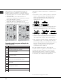
Practical advice on using the burners
To ensure the burners operate efficiently:
• Use appropriate cookware for each burner (see
table) so that the flames do not extend beyond the
bottom of the cookware.
• Always use cookware with a flat base and a cover.
• When the contents of the pan reach boiling point,
turn the knob to minimum.
Burner
Reduced Rapid (RR)
Semi-Rapid (S)
Auxiliary (A)
Semi-Fishburner (SP)
Double Flame (DCDR internal)
Double Flame (DCDR external)
Ø Cookware Diameter (cm)
24 - 26
16 - 20
10 - 14
16 - 20
10 - 14
26 - 28
Pans to be used on 75 cm hobs
Burner
Rapid (R)
Semi-Rapid (S)
Auxiliary (A)
Double Flame (DCDR internal)
Double Flame (DCDR external)
Ø Cookware Diameter (cm)
24 - 26
16 - 20
10 - 14
10 - 14
24 - 26
Pans to be used on 60 cm hobs
! On the models supplied with a reducer shelf,
remember that this should be used only for the Double
flame internal (DCDR internal) burner when you use
casserole dishes with a diameter under 12 cm.
To identify the type of burner, refer to the designs in
the section entitled, "Burner and Nozzle
Specifications".
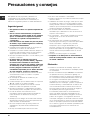
Practical Advice on Using the Half Fish-Kettle
Burner *
The two "Half Fish-Kettle" burners, are eliptic in form
and can be turned up to 90°. This makes the cooktop
more flexible in terms of how it can be used.
To turn the two burners 90°, proceed as follows:
• Make sure that the burners are cool;
• Lift the burner completely out of its housing;
• Replace it in its housing in the position desired;
• Make sure that the burners are positioned
correctly before use.
In addition, the two burners can be used in tandem
or speartely with cookware of different shapes and
sizes:
• Double burner for a fish-kettle or oval cookware
(Fig.A).
*
Only available on certain models.

GB
10
• Double burner for a griddle or rectangular/square
cookware with minimum dimensions of 28x28 cm
(Fig.B)
• Single burner for medium size cookware (diameter
of 16-20 cm) (Fig.C).
• NEVER use the double burner in the configuration
represented in figure D.
Fig. A Fig. B
Fig. C Fig. D
Practical Advise on Using the Ceramic
Glass Module*
Set.
0
1
2
3
4
5
6
7
8
9
10
11
12
Radiant Burner
Off.
To melt butter and chocolate.
To heat liquids.
For creams and sauces.
For cooking at the boiling point.
For Roasts.
For boiling large pieces of meat.
For frying.
For utilising both cooking areas.
To obtain the best results from your hob:
• Use flat-bottomed pans to ensure that they adhere
to the cooking zone perfectly.
• Always use pans with a diameter that is large
enough to cover the hotplate fully, in order to use
all the available heat.
• Make sure that the bottom of the cookware is
always dry and clean to guarantee correct
adherence and long life, not only for the cooking
zones but also for the cookware itself.
• Avoid using the same cookware that is used on
gas burners: the heat concentration on gas
burners may deform the base of the pan, causing
it not to adhere correctly.
• Never leave a cooking zone on without cookware
on it because as it heats up and rapidly reaches
the maximum level, which could damage the
heating elements.
! The glue used for sealing the glass may leave
greasy residues. We recommend removing them
with a non-abrasive cleaning product prior to
operating the appliance. During the first few hours of
operation, there may be a smell of rubber that will
soon disappear.

GB
11
Precautions and tips
! This appliance has been designed and manufactured
in compliance with international safety standards. The
following warnings are provided for safety reasons and
must be read carefully.
General safety
• This is a class 3 built-in appliance.
• Gas appliances require regular air exchange to
maintain efficient operation. When installing the
hob, follow the instructions provided in the
paragraph on “Positioning” the appliance.
• These instructions are only valid for the countries
whose symbols appear in the manual and on the
serial number plate.
• The appliance was designed for domestic use inside
the home and is not intended for commercial or
industrial use.
• The appliance must not be installed outdoors, even in
covered areas. It is extremely dangerous to leave the
appliance exposed to rain and storms.
• Do not touch the appliance with bare feet or with wet
or damp hands and feet.
• The appliance must be used by adults only for the
preparation of food, in accordance with the
instructions outlined in this booklet. Any other
use of the appliance (e.g. for heating the room)
constitutes improper use and is dangerous. The
manufacturer may not be held liable for any
damage resulting from improper, incorrect and
unreasonable use of the appliance.
• Ensure that the power supply cables of other
electrical appliances do not come into contact with
the hot parts of the oven.
• The openings used for ventilation and dispersion of
heat must never be covered.
• Always make sure the knobs are in the “”/“
”
position when the appliance is not in use.
• When unplugging the appliance always pull the plug
from the mains socket, do not pull on the cable.
• Never carry out any cleaning or maintenance work
without having detached the plug from the mains.
• In case of malfunction, under no circumstances
should you attempt to repair the appliance yourself.
Repairs carried out by inexperienced persons may
cause injury or further malfunctioning of the
appliance. Contact a Service Centre (see
Assistance).
• Always make sure that pan handles are turned
towards the centre of the hob in order to avoid
accidental burns.
• Do not close the glass cover (if present) when the gas
burners or electric hotplates are still hot.
• Do not leave the electric hotplate switched on without
a pan placed on it.
• Do not use unstable or deformed pans.
• Remove any liquid from the lid before
opening it.
• Prevent children and the disabled from coming into
contact or having access at the ceramic glass
cooking surface (if present) immediately before and
after use, as the cooking surface will remain hot for at
least a half hour after being turned off;
• Contact service centers authorized by the
manufacturer in the event the ceramic glass cooking
surface breaks.
• It is recommended that you follow the guidelines
below:
• Disconnect the appliance from the electrical supply in
the event the ceramic glass cooking surface
breakds.
• The appliance should not be operated by people
(including children) with reduced physical, sensory or
mental capacities, by inexperienced individuals or by
anyone who is not familiar with the product. These
individuals should, at the very least, be supervised
by someone who assumes responsibility for their
safety or receive preliminary instructions relating to
the operation of the appliance.
• Do not let children play with the appliance.
• The appliance is not intended to be operated by
means of an external timer or separate remote-
control system.
Disposal
• When disposing of packaging material: observe local
legislation so that the packaging may be reused.
• The European Directive 2002/96/EC on Waste
Electrical and Electronic Equipment (WEEE), requires
that old household electrical appliances must not be
disposed of in the normal unsorted municipal waste
stream. Old appliances must be collected separately
in order to optimise the recovery and recycling of the
materials they contain and reduce the impact on
human health and the environment. The crossed out
“wheeled bin” symbol on the product reminds you of
your obligation, that when you dispose of the
appliance it must be separately collected.
Consumers may take their old appliance to public
waste collection areas, other communal collection
areas, or if national legislation allows return it to a
retailer when purchasing a similar new product.
All major household appliance manufacturers are
active in the creation of systems to manage the
collection and disposal of old appliances.

GB
12
Switching the appliance off
Disconnect your appliance from the electricity supply
before carrying out any work on it.
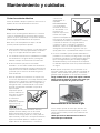
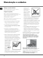
Cleaning the appliance
! Do not use abrasive or corrosive detergents such as
stain removers, anti-rust products, powder detergents
or sponges with abrasive surfaces: these may scratch
the surface beyond repair.
! Never use steam cleaners or pressure cleaners on
the appliance.
• It is usually enough to wash the hob with a damp
sponge and dry it with absorbent kitchen roll.
• The removable parts of the burners should be
washed frequently with warm water and soap and
any burnt-on substances removed.
• For hobs which ligth automatically, the terminal part
of the electronic instant lighting devices should be
cleaned frequently and the gas outlet holes should
be checked for blockages.
• Stainless steel can be marked by hard water that
has been left on the surface for a long time, or by
aggressive detergents containing phosphorus.
After cleaning, rinse and dry any remaining drops
of water.
• Before using the ceramic glass module, the surface
must be cleaned, using a damp cloth to remove
dust or food residues. The ceramic glass surface
should be cleaned regularly with a soultion of warm
water and a non-
abrasive detergent.
Periodically, special
products will need to
be used to clean the
surface. First,
remove all food
buildup or grease
with a cleaning
scraper, e.g.
(not
supplied.
Clean the cooking surface when it is still warm with
a suitable cleaning product (such as the one in the
Solutions product line available from any After-
Sales Service Centre) and paper towels. Then rub
with a damp cloth and dry. Aluminum foil, plastic
Maintenance and care
items, objects made of synthetic material, sugar
or foods with a high sugar content that have
melted onto the surface must be removed
immediatley with a scraper while the cooking
surface is still hot. Special cleaning products for
ceramic glass surfaces form a transparent
protective layer which fights diry buildup. This
also protects the surface from damage caused by
food with a high
sugar content. Do
not use abrasive
sponges or cleaning
products under any
circumstances. This
holds true for
chemically
aggressive cleaners,
like oven sprays and
stain removers.
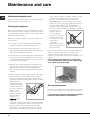
! It is not necessary to remove the pan supports in
order to clean the hob surface. Thanks to the
support system, simply lift and hold the pan
supports or rotate them until they rest against a rear
support.
Do not place the hot grids on top of the glass
cover (if applicable), otherwise the rubber plugs
on the glass may be damaged.
Gas tap maintenance
Over time, the taps may become jammed or difficult
to turn. If this happens, the tap must be replaced.
! This procedure must be performed by a qualified
technician authorised by the manufacturer.

GB
13
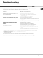
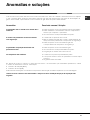
Troubleshooting
It may happen that the appliance does not function properly or at all. Before calling the service centre for
assistance, check if anything can be done. First, check to see that there are no interruptions in the gas and
electrical supplies, and, in particular, that the gas valves for the mains are open.
Problem
The burner does not light or the flame is not
even around the burner.
The flame dies in models with a safety device.
The burner does not remain lit when set to
minimum.
The cookware is unstable.
Possible causes/Solution
• The gas holes on the burner are clogged.
• All the movable parts that make up the burner are
mounted correctly.
• There are draughts near the appliance.
• You pressed the knob all the way in.
• You keep the knob pressed in long enough to activate the
safety device.
• The gas holes are not blocked in the area corresponding
to the safety device.
• The gas holes are not blocked.
• There are no draughts near the appliance.
• The minimum setting has been adjusted properly.
• The bottom of the cookware is perfectly flat.
• The cookware is positioned correctly at the centre of the
burner.
• The pan support grids have been positioned correctly.
If, despite all these checks, the hob does not function properly and the problem persists, call the nearest
Customer Service Centre. Please have the following information handy:
• The appliance model (Mod.).
• The serial number (S/N).
This information can be found on the data plate located on the appliance and/or on the packaging.
! Never use unauthorised technicians and never accept replacement parts which are not original.

ES
14
ENCIMERA
PK 741 RQO GH AG
PK 750 RL GH AG
PK 640 RL GH AG
PK 760 RF GH AG
Sumario
Instalación, 15-21
Colocación
Conexión eléctrica
Conexión gas
Características de los quemadores e inyectores
Placa de características
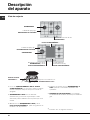
Descripción del aparato, 22
Vista de conjunto
Puesta en funcionamiento y uso, 23-25
Consejos prácticos para el uso de los quemadores
Consejos prácticos para el uso de la placa
Vitrocerámica
Precauciones y consejos, 26
Seguridad general
Eliminación
Mantenimiento y cuidados, 27
Cortar la corriente eléctrica
Limpiar el aparato
Mantenimiento de las llaves de gas
Placa de características
Anomalías y soluciones, 28
Manual de
instrucciones
Español, 14
ES
Português, 29
PT
English,1
GB

ES
15
! Es importante conservar este manual para poder
consultarlo en todo momento. En caso de venta, de cesión
o de mudanza, verifique que permanezca junto al aparato
para informar al nuevo propietario sobre su funcionamiento
y sobre las advertencias correspondientes.
! Lea atentamente las instrucciones: contienen importante
información sobre la instalación, el uso y la seguridad.
Colocación
! Los embalajes no son juguetes para niños y se deben
eliminar respetando las normas para la recolección de
residuos (ver Precauciones y consejos).
! La instalación se debe realizar siguiendo estas
instrucciones y por personal profesionalmente calificado.
Una instalación incorrecta puede producir daños a
personas, animales o cosas.
! Este aparato puede ser instalado y funcionar sólo en
lugares ventilados permanentemente, de acuerdo a las
prescripciones de l’Orden de 29.03.1974. Deben ser
observados los siguentes requisitos:
• El ambiente debe poseer un sistema de descarga de los
humos de la combustión al exterior, utilizando una
campana o un electroventilador que entre
automáticamente en funcionamiento cada vez que se
enciende el aparato.
• El ambiente debe poseer un sistema que permita la
entrada del aire necesario para una combustión normal.
El caudal de aire necesario para la combustión no debe
ser inferior a 2 m
3
/h por cada kilovatio (kW) de potencia
instalada.
El sistema puede tomar aire del
exterior del edificio a través de un
conducto de 100 cm
2
, como
mínimo, de sección útil de modo
que no pueda ser obstruido
accidentalmente.
También puede hacerlo de
manera indirecta, desde
ambientes adyacentes que
posean un conducto de
ventilación hacia el exterior, como
se describe más arriba, y que no
sean partes en común del
inmueble, ambientes con peligro
de incendio o dormitorios.
• Los gases de petróleo licuados, más pesados que el aire,
se depositan en las partes más bajas. Por lo tanto, los
ambientes que contienen botellas de GPL deben tener
aberturas hacia el exterior para permitir la evacuación
desde abajo de eventuales escapes de gas. Además, las
botellas de GPL, vacías o parcialmente llenas, no deben
ser instaladas o depositadas en ambientes o espacios a un
nivel más bajo del suelo (sótanos, etc.) Es conveniente
conservar en el ambiente sólo la botella que se está
utilizando, colocada de modo que no quede expuesta a la
acción directa de fuentes de calor (hornos, chimeneas,
estufas, etc.) capaces de llevarla a temperaturas superiores
a 50°C.
Empotramiento
Las encimeras a gas y mixtas están fabricadas con un grado de
protección contra calentamientos excesivos de tipo X, y por lo
tanto, es posible su instalación al lado de muebles cuya altura no
supere la de la superficie de trabajo. Para una correcta instalación
de la encimera se deben observar las siguientes precauciones:
• Los muebles situados a un costado, cuya altura supere la
de la superficie de trabajo, deben estar situados a 600
mm., como mínimo, del borde de la misma.
• Las campanas deben ser instaladas de acuerdo con los
requisitos establecidos en los manuales de instrucción
de las mismas, siempre manteniendo una distancia
mínima de 650 mm.
• Coloque los armarios de pared adyacentes a la campana
a una altura mínima desde la superficie de trabajo, de
420 mm. (ver la figura).
Siempre que la encimera se
instale debajo de un armario de
pared, éste último deberá
mantener una distancia mínima de
la superficie de trabajo de 700
mm. (ver la figura).
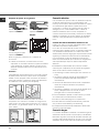
• El espacio para el mueble deberá tener las dimensiones
indicadas en la figura. Se han previsto ganchos de fijación
que permiten fijar la encimera a superficies de 20 a 40 mm.
de espesor. Para un buena fijación de la encimera, es
aconsejable usar todos los ganchos que se suministran.
555 mm
55 mm
475 mm
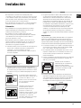
Instalación
Aumento de la ranura entre
puerta y suelo
Habitación
adyacente
Habitación
por ventilar
A
Ejemplos de aperture
de ventilación
para aire comburente
En chimenea o tubo de chimenea ramificado
(reservado a los aparatos de cocción)
Directamente
al externo
600mm min.
600mm min.
700mm min.

ES
16
560 mm.
4
5
m
m
.
Esquema de fijación de los ganchos
Posición del gancho para Posición del gancho para
superficies
H=20mm superficies H=30mm
Adelante
Posición del gancho para Atrás
superficies
H=40mm
! Use los ganchos contenidos en el “paquete de
accesorios”
• Cuando la encimera no se instale sobre un horno
empotrado, es necesario introducir un panel de madera
como aislamiento. El mismo deberá colocarse a una
distancia mínima de 20 mm. de la pared inferior de la
encimera.
Aireación
Para garantizar una buena aireación es necesario eliminar
la pared posterior del hueco para el horno. Es preferible
instalar el horno apoyado sobre dos listeles de madera o
sobre una superficie continua que tenga una abertura de
45 x 560 mm. como mínimo (ver las figuras).
Cuando se trate de instalación sobre un horno
empotrable sin ventilación forzada de refrigeración,
para permitir una adecuada ventilación en el interior
del mueble, se garantizan tomas de aire de entrada
y de salida.
Conexión eléctrica
Las encimeras que poseen cable de alimentación tripolar,
se fabrican para funcionar con corriente alterna, a la
tensión y frecuencia de alimentación indicadas en la placa
de características (ubicada en la parte inferior de la
encimera). El conductor de puesta a tierra del cable se
distingue por los colores amarillo-verde. Cuando se
realiza la instalación sobre un horno empotrado, la
conexión eléctrica de la encimera y la del horno se deben
realizar por separado, ya sea por razones de seguridad
eléctrica, como para facilitar la eventual extracción del
horno.
Conexión del cable de alimentación eléctrica a la red
Instale en el cable un enchufe normalizado para la carga
indicada en la placa de características.
En el caso de conexión directa a la red, es necesario
interponer entre el aparato y la red, un interruptor omnipolar
con una distancia mínima entre los contactos de 3 mm.,
dimensionado para esa carga y que responda a las normas
vigentes (el conductor de tierra no debe ser interrumpido
por el interruptor). El cable de alimentación eléctrica se
debe colocar de modo tal que no alcance en ningún punto
una temperatura que supere en 50°C la temperatura
ambiente.
! El instalador es responsable de la correcta conexión
eléctrica y del cumplimiento de las normas de seguridad.
Antes de efectuar la conexión verifique que:
• la toma tenga conexión a tierra y que sea conforme con
la ley;
• la toma sea capaz de soportar la carga máxima de
potencia de la máquina indicada en la placa de
características;
• la tensión de alimentación eléctrica esté comprendida
dentro de los valores indicados en la placa de
características;
• la toma sea compatible con el enchufe del aparato. Si no
es así, sustituya la toma o el enchufe; no utilice
prolongaciones ni conexiones múltiples.
! Una vez instalado el aparato, el cable eléctrico y la toma
de corriente deben ser fácilmente accesibles.
! El cable no debe sufrir pliegues ni compresiones.
! El cable debe ser revisado periódicamente y sustituido
sólo por técnicos autorizados (ver Asistencia).
! La empresa declina toda responsabilidad cuando estas
normas no sean respetadas.
Conexión de gas
La conexión del aparato a la tubería o a la botella de gas se
deberá efectuar de acuerdo a lo prescripto por las Normas
Nacionales vigentes, sólo después de haber verificado que
el mismo está regulado para el tipo de gas con el cual será
alimentado. Si no es así, realice las operaciones indicadas

ES
17
en el párrafo “Adaptación a los distintos tipos de gas”.
En el caso de alimentación con gas líquido, desde
botella, utilice reguladores de presión conformes con las
Normas Nacionales vigentes.
! Para un funcionamiento seguro, un adecuado uso de la
energía y una mayor duración del aparato, verifique que la
presión de alimentación cumpla con los valores indicados
en la tabla 1 “Características de los quemadores e
inyectores”.
Conexión con tubo rígido (cobre o acero)
! La conexión a la red de gas se debe efectuar de modo
que no provoque esfuerzos de ningún tipo al aparato.
En el tubo de alimentación del aparato se encuentra una
unión en “L” orientable, cuya estanqueidad está asegurada
por una junta. Si resultara necesario girar la unión, sustituya
siempre la junta estanca (suministrada con el aparato). La
unión de entrada de gas al aparato es roscada 1/2 gas
macho cilíndrico.
Conexión con tubo flexible de acero inoxidable de pared
continua con uniones roscadas
La unión de entrada de gas al aparato es roscada 1/2 gas
macho cilíndrico.
La colocación de dichos tubos se debe efectuar de modo
tal que su longitud, en condiciones de máxima extensión,
no sea mayor que 2000 mm. Una vez realizada la conexión,
verifique que el tubo metálico flexible no permanezca en
contacto con partes móviles o no quede aplastado.
! Utilice exclusivamente tubos y juntas estancas conformes
a la Normas Nacionales en vigencia.
Control de la estanqueidad
! Finalizada la instalación, controle la perfecta estanqueidad
de todas las uniones utilizando una solución jabonosa pero
nunca una llama.
Adaptación a los distintos tipos de gas
Para adaptar la encimera a un tipo de gas diferente de
aquel para el que fue fabricada (indicado en la etiqueta
fijada en la parte inferior de la encimera o en el embalaje),
es necesario sustituir los inyectores de los quemadores
efectuando las siguientes operaciones:
1. quite las parrillas de la encimera y extraiga los
quemadores.
2. desenrosque los inyectores utilizando una llave tubular
de 7mm. y sustitúyalos por los que se adapten al nuevo
tipo de gas (ver tabla 1 “Características de los
quemadores e inyectores”).
3. vuelva a colocar las piezas realizando las operaciones
en sentido contrario.
4. al finalizar la operación, sustituya la anterior etiqueta de
calibrado con la correspondiente al nuevo gas que se va
a utilizar, disponible en nuestros Centros de Asistencia
Técnica.
Sustitución de los picossen el quemador “doble
llama” independente:
• sacar las rejillas y quitar los quemadores de sus
sedes. El quemador está compuesto de 2 partes
separados (ver Fig. E y Fig. F)
• destornillar los picos, sirviéndose de una llave de tubo
de 7 mm. El quemador interno tiene un pico, el
quemador externo tiene dos (del mismo tamaño).
Reemplazar los picos por los que se adapten al nuevo
tipo de gas (ver tabla 1).
• Volver a colocar todos los componentes en sus
respectivas posiciones, efectuando las operaciones
inversas, respecto a la secuencia arriba indicada.
• Regulación de aire principal de los quemadores
Los quemadores no necesitan de ninguna regulación de
aire principal.
• Regulación de los mínimos
1. Lleve la llave hasta la posición de mínimo;
2. Quite el mando y accione el tornillo de regulación situado
en el interior o al costado de la varilla de la llave hasta
conseguir una pequeña llama regular.
! En el caso del quemador DCDR monomando, la
regulación se debe realizar con los 2 tornillos
ubicados al costado de la varilla del grifo (ver la
figura).
3. Verifique que girando rápidamente el mando desde la
posición de máximo hasta la de mínimo, no se
apaguen los quemadores.
4. En los aparatos provistos del dispositivo de seguridad
(termopar), si dicho dispositivo no funcionara con los
quemadores al mínimo, aumente la capacidad de los
mínimos utilizando para ello el tornillo de regulación.
5. Una vez efectuada la regulación, vuelva a colocar los
precintos ubicados en los by-pass con lacre o un
material equivalente.
6. En el caso de mandos con regulación discreta y
visualización con led, coloque el mando en la
Regulación
DCDR interno
Regulación
DCDR total

ES
18
posición de mínimo, luego extraiga el mando y
trabaje con el tornillo de regulación ubicado al
costado de la varilla del grifo.
7. Regulación de los mínimos del quemador DCDR
con regulación discreta y visualización con led:
• para regular la corona externa, gire el mando
en sentido antihorario hasta la posición de
mínimo;
• para regular el mínimo de la corona interna,
gire el mando en sentido horario hasta la posición
de mínimo;
• extraiga el mando y trabaje con el tornillo de
regulación ubicado al costado de la varilla del
grifo.
! En el caso de ga
s líquido, el tornillo de regulación
deberá enroscarse a fondo.
! Al finalizar la operación, sustituya la anterior etiqueta de
calibrado con la correspondiente al nuevo gas que se va
a utilizar, disponible en nuestros Centros de Asistencia
Técnica.
! Cuando la presión del gas utilizado sea distinta de la
prevista (o variable), es necesario instalar, en la tubería de
entrada, un regulador de presión conforme con las
Normas Nacionales en vigencia.
Conexiones
eléctricas
PLACA DE CARACTERÍSTICAS
ver placa de características
Este aparato es conforme con las
siguientes Normas Comunitarias:
- 2006/95/CEE del 12/12/06 (Baja
Tensión) y posteriores modificaciones
- 2004/108/CEE del 15/12/04
(Compatibilidad Electromagnética) y
posteriores modificaciones
- 93/68/CEE del 22/07/93 y posteriores
modificaciones.
- 2009/142/CEE del 30/11/09 (Gas) y
posteriores modificaciones.
- 2002/96/CEE y posteriores
modificaciones successives.

ES
19
HORNALLA
Presión de trabajo para Gas Natural 180 mm c.a - Preparado para GN convertible a GPL
Presión de trabajo para Gas Licuado 280 mm c.a
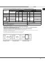
N°
IN Y
GAS LICUADO GAS NATURAL
KW KCAL/H Inyector
1/100 (mm)
KW KCAL/H Inyector 1/100 (mm)
AUXILAR 1 1,00 860 50 860 79
SEMI-
RÁPIDO
1 1,65 1419 64 1419 106
RÁPIDO 1 2,60 2236 86 2236 116
TOTAL 6 8,85 7610 - 7610 -
Tension de alimentacion 220-240 V~ 50-60Hz
Potencia: 0,6 W
Clase del artefacto: 3
Categoria de gas: II2H3B/P
INDUSTRIA ITALIANA
Importador: Indesit Argentina S.A.
Aprobado bajo norma:
NAG 312
(1) Sólo para DCDR monomando
IMPORTANTE: NO INSTALAR EN LUGARES SIN VENTILACION PERMANENTE
ESTE ARTEFACTO DEBE SER INSTALADO, DE ACUERDO CON LAS NORMASY REGLAMENTACIONES EN
VIGENCIA, FOR UN INSTALADOR MATRICULADO
CONSULTAR LAS INSTRUCCIONES ANTES DE INSTALAR Y UTILIZAR ESTE ARTEFACTO
AV.EDUARDO MANDERO 900 PISO 18 BUENOS AIRES; TEL. 011-4131-1513
Este artefacto esta preparado para trabajar con gas natural 18mb para gas natural. Se provee el juego de inyectores
para realizar el cambio de tipo de gas.
Sr. Instalador: en el caso de cambio de tipo de gas, sirvase aclararlo.
Tipo de gas: NATURAL/LICUADO (tache lo que no corrisponde)
1,00
1,65
2,60
8,85
Doble
llama
(1)
(DCDR
Interno)
(DCDR
Externo
2 pico.)
Características de los quemadores e inyectores (sólo modelo PK 640 R L GH AG)
3 3,60 3095
44
3095
74
60 x2 94 x2
3,60
PK 640 RL GH AG
RR
DC
S
A

ES
20
HORNALLA
Presión de trabajo para Gas Natural 180 mm c.a - Preparado para GN convertible a GPL
Presión de trabajo para Gas Licuado 280 mm c.a
N°
IN Y
GAS LICUADO GAS NATURAL
KW KCAL/H Inyector
1/100 (mm)
KW KCAL/H Inyector 1/100 (mm)
AUXILAR 1 1,00 860 50 860 79
SEMI-
RÁPIDO
1
1,65 1419 64 1419 106
TOTAL 5 7,25 6235 - 6579 -
Tension de alimentacion 220-240 V~ 50-60Hz
Potencia: 2000 W
Clase del artefacto: 3
Categoria de gas: II2H3B/P
INDUSTRIA ITALIANA
Importador: Indesit Argentina S.A.
Aprobado bajo norma:
NAG 312
(2) Sólo para DCDR doble comando
IMPORTANTE: NO INSTALAR EN LUGARES SIN VENTILACION PERMANENTE
ESTE ARTEFACTO DEBE SER INSTALADO, DE ACUERDO CON LAS NORMASY REGLAMENTACIONES EN
VIGENCIA, FOR UN INSTALADOR MATRICULADO
CONSULTAR LAS INSTRUCCIONES ANTES DE INSTALAR Y UTILIZAR ESTE ARTEFACTO
AV.EDUARDO MANDERO 900 PISO 18 BUENOS AIRES; TEL. 011-4131-1513
Este artefacto esta preparado para trabajar con gas natural 18mb para gas natural. Se provee el juego de inyectores
para realizar el cambio de tipo de gas.
Sr. Instalador: en el caso de cambio de tipo de gas, sirvase aclararlo.
Tipo de gas: NATURAL/LICUADO (tache lo que no corrisponde)
1,00
1,65
144 70
2
4,60 3956
70 x2
4300
114 x2
5,00
7,65
Características de los quemadores e inyectores (sólo modelo PK 741 RQO GH AG)
Doble llama
(DCDR Interno) (2)
Doble llama
(DCDR Externo)
2 Pico (2)
HORNALLA
Presión de trabajo para Gas Natural 180 mm c.a - Preparado para GN convertible a GPL
Presión de trabajo para Gas Licuado 280 mm c.a
N°
IN Y
GAS LICUADO GAS NATURAL
KW KCAL/H Inyector
1/100 (mm)
KW KCAL/H Inyector 1/100 (mm)
AUXILAR 1 1,00 860 50 860 79
SEMI-
RÁPIDO
2
1,65 1419 64 1419 106
RÁPIDO 1 2,60 2236 86 2236 116
TOTAL 7 11,50 9890 - 10234 -
Tension de alimentacion 220-240 V~ 50-60Hz
Potencia: 0,6 W
Clase del artefacto: 3
Categoria de gas: II2H3B/P
INDUSTRIA ITALIANA
Importador: Indesit Argentina S.A.
Aprobado bajo norma:
NAG 312
(1) Sólo para DCDR monomando
IMPORTANTE: NO INSTALAR EN LUGARES SIN VENTILACION PERMANENTE
ESTE ARTEFACTO DEBE SER INSTALADO, DE ACUERDO CON LAS NORMASY REGLAMENTACIONES EN
VIGENCIA, FOR UN INSTALADOR MATRICULADO
CONSULTAR LAS INSTRUCCIONES ANTES DE INSTALAR Y UTILIZAR ESTE ARTEFACTO
AV.EDUARDO MANDERO 900 PISO 18 BUENOS AIRES; TEL. 011-4131-1513
Este artefacto esta preparado para trabajar con gas natural 18mb para gas natural. Se provee el juego de inyectores
para realizar el cambio de tipo de gas.
Sr. Instalador: en el caso de cambio de tipo de gas, sirvase aclararlo.
Tipo de gas: NATURAL/LICUADO (tache lo que no corrisponde)
1,00
1,65
2,60
11,90
Doble
llama
(1)
(DCDR
Interno)
(DCDR
Externo
2 pico.)
Características de los quemadores e inyectores (sólo modelo PK 750 RL GH AG)
1
2
4,60 3956
44
4300
74
60 x2 94 x2
5,00
A página está carregando...
A página está carregando...
A página está carregando...
A página está carregando...
A página está carregando...
A página está carregando...
A página está carregando...
A página está carregando...
A página está carregando...
A página está carregando...
A página está carregando...
A página está carregando...
A página está carregando...
A página está carregando...
A página está carregando...
A página está carregando...
A página está carregando...
A página está carregando...
A página está carregando...
A página está carregando...
A página está carregando...
A página está carregando...
-
 1
1
-
 2
2
-
 3
3
-
 4
4
-
 5
5
-
 6
6
-
 7
7
-
 8
8
-
 9
9
-
 10
10
-
 11
11
-
 12
12
-
 13
13
-
 14
14
-
 15
15
-
 16
16
-
 17
17
-
 18
18
-
 19
19
-
 20
20
-
 21
21
-
 22
22
-
 23
23
-
 24
24
-
 25
25
-
 26
26
-
 27
27
-
 28
28
-
 29
29
-
 30
30
-
 31
31
-
 32
32
-
 33
33
-
 34
34
-
 35
35
-
 36
36
-
 37
37
-
 38
38
-
 39
39
-
 40
40
-
 41
41
-
 42
42


Ariston PK 640 R L GH AG Guia de usuario
- Categoria
- Fogões
- Tipo
- Guia de usuario
- Este manual também é adequado para
em outras línguas
- español: Ariston PK 640 R L GH AG Guía del usuario
- English: Ariston PK 640 R L GH AG User guide
Artigos relacionados
-
Indesit PCN 761 S/IX/A Guia de usuario
-
-
-
-
-
Whirlpool PH 640 M (IX) AG Guia de usuario
-
-
-
-
Ariston TD 640 S (BK) IX Guia de usuario
Outros documentos
-
-
-
-
-
Whirlpool PK 760 RF X /HA Instruções de operação
-
-
-
-
Whirlpool TG 640 (WH) Guia de usuario
-