
Motors | Automation | Energy | Transmission & Distribution | Coatings
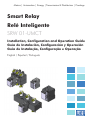
Smart Relay
Relé Inteligente
SRW 01-UMCT
Installation, Configuration and Operation Guide
Guía de Instalación, Configuración y Operación
Guia de Instalação, Configuração e Operação
English / Español / Português


SUMMARY
I. Safety Instructions ................................................... 5
II. General Information .............................................. 5
III. Contents of the Package ........................................ 5
1. Installation ............................................................ 5
2. Mechanical Installation .......................................... 6
3. Electrical Installation .............................................. 6
4. Installation Procedure ............................................ 7
5. Dimensions ..........................................................10
6. Maximum Cross Section and Tightening
Torque Connection (Main Terminals) .......................... 15
7. Accessories .......................................................... 16
ÍNDICE
I. Instrucciones de Seguridad .....................................17
II. Informaciones Generales ....................................... 17
III. Contenido del Embalaje .......................................17
1. Instalación ........................................................... 17
2. Instalación Mecánica ............................................18
3. Instalación Eléctrica .............................................. 18
4. Procedimiento de Instalación ................................. 19
5. Dimensiones ........................................................ 22
6. Sección Máxima y Torque de Conexión
(Terminales Principales) ............................................. 27
7. Accesorios ........................................................... 28

ÍNDICE
I. Instruções de Segurança ........................................ 29
II. Informações Gerais ..............................................29
III. Conteúdo da Embalagem..................................... 29
1. Instalação ............................................................ 29
2. Instalação Mecânica ............................................. 30
3. Instalação Elétrica ................................................ 30
4. Procedimento de Instalação .................................. 31
5. Dimensões ........................................................... 34
6. Seção Máxima e Torque de Conexão ..................... 39
7. Acessórios ...........................................................40

5
- English -
Installation, Conguration and Operation Guide of the SRW01
UMCT (Current/Voltage Measurement Unit)
I. SAFETY INSTRUCTIONS
All the safety procedures described in the SRW 01 manual must be
followed. Failure to comply with the recommended safety instructions may
result in death, serious injury and considerable material damage.
II. GENERAL INFORMATION
This guide orients the installation, configuration and operation of the
Current/Voltage Measurement Unit (UMCT) of the SRW 01 Smart Relay.
III. CONTENTS OF THE PACKAGE
- SRW 01 Current/Voltage Measurement Unit;
- Installation, configuration and operation guide.
1. INSTALLATION
The orientations and suggestions must be followed aiming to the
correct operation, and to people and equipment safety. The procedures
are divided into:
- Mechanical installation;
- Electrical installation.

6
- English -
2. MECHANICAL INSTALLATION
The Current/Voltage Measurement Unit (UMCT) can be installed in
any position.
The UMCT´s 1, 2, 3 and 4 can be mounted directly on a 35 mm
(1.38 in) DIN rail or fixed by means of M4 screws, using the screw fixing
adapter (PLMP).
The UMCT´s 5 and 6 present only the M4 screw mounting possibility.
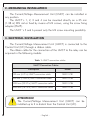
3. ELECTRICAL INSTALLATION
The Current/Voltage Measurement Unit (UMCT) is connected to the
Control Unit (UC) through a ribbon cable.
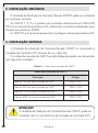
The ribbon cable for the connection of the UMCT to the relay can be
acquired in the following models:
Table 1: UMCT connection cables
UMCT Connection Cables
Description Model
120 mm (4.72 in) UMCT connection cable SRW01-CB1
500 mm (19.68 in) UMCT connection cable SRW01-CB2
1000 mm (39.37 in) UMCT connection cable SRW01-CB4
2000 mm (78.74 in) UMCT connection cable SRW01-CB3
ATTENTION!
The Current/Voltage Measurement Unit (UMCT) can be
installed up to 2 m distant from the Control Unit (UC).

7
- English -
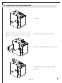
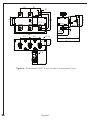
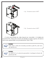
4. INSTALLATION PROCEDURE
1 - UMCT
2 - SRW01-CBx connection cable
3 - 35 mm (1.38 in) DIN rail mounting
4 - Secured by screw using the PLMP
accessory

8
- English -
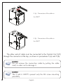
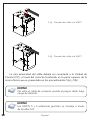
5 (a) - Connection of the cable to
the UMCT
5 (b) - Connection of the cable to
the UMCT
The other end of cable must be connected to the Control Unit (UC)
through the connector at the top, as shown in procedures 5 (a) and 5 (b).
NOTE!
Do not remove the connection cable by pulling the cable
itself, in order not to damage it.
NOTE!
The 5 and 6 UMCT’s present only the M4 screw mounting
possibility.

9
- English -
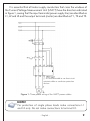
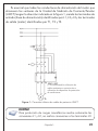
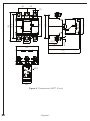
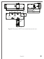
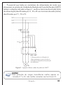
It is essential that all motor supply conductors that cross the windows of
the Current/Voltage Measurement Unit (UMCT) have the direction indicated
in figure 1, seeing that the input terminals (power supply line) are identified as
L1, L2 and L3 and the output terminals (motor) are identified as T1, T2 and T3.
(*) It is recommended to use short-circuit
resistant cables or conductor protection
devices.
Figure 1: Three-phase wiring of the UMCT power cables
NOTE!
For protection of single phase loads make connections L1
and L2 only. Do not make connections to terminal L3.

10
- English -
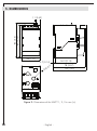
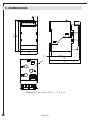
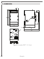
5. DIMENSIONS
11 (0.43)
84 (3.3)
3.7 (0.14)
54.3 (2.14)
78 (3.07)
82 (3.22)
Ø 8 (0.31)
45 (1.77)
80 (3.15)
Figure 2: Dimensions of the UMCT 1, 2, 3 in mm (in)

11
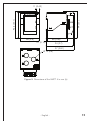
- English -
11 (0.43)
Ø 15 (0.6)
94 (3.7)
97 (3.81)
3.7 (0.14)
68 (2.68)
66 (2.6)
94 (3.7)
94.2 (3.71)
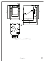
Figure 3: Dimensions of the UMCT 4 in mm (in)

12
- English -
45 (1.77)
45 (1.77)
25 (0.98)
155 (6.1)
130 (5.12)
40 (1.57)
45 (1.77)
110 (4.33)
127 (4)
M10
84 (3.31)
49.5 (1.95)
76.5 (3.01)
167 (6.57)
171 (6.73)
120 (4.72)
Ø 8 (0.31)
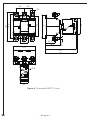
Figure 4: Dimensions of the UMCT 5 in mm (in)

13
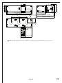
- English -
70 (2.75)
250.5 (9.86)
90 (3.54)
181.90 (7.16)
185.5 (7.30)
84.46 (3.32)
81 (3.19)81 (3.19)
Ø 34 (1.33)
45.5 (1.79)
45 (1.77)
70 (2.75)
Ø 8 (0.31)
50 (1.97)
265 (10.43)
Ø 5 (0.2)
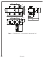
Figure 5: Dimensions of the UMCT 6 (without accessories bars) in mm (in)

14
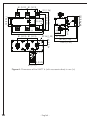
- English -
81 (3.19)
81 (3.19)
81 (3.19)
81 (3.19)
32 (1.26)
70 (2.75)
50 (1.97)
250.5 (9.86)
265 (10.43)
120 (4.72)
150 (5.9)
M12
Ø 5 (0.2)
Ø 34 (1.33)
84.46 (3.32)
91 (3.58)
50.3
(1.98)
185.5 (7.30)
181.90 (7.16)
45.5 (1.79)
Ø 8 (0.31)
70 (2.75)
45 (1.77)
Figure 6: Dimensions of the UMCT 6 (with accessories bars) in mm (in)

15
- English -
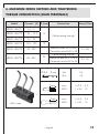
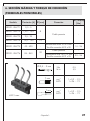
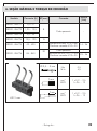
6. MAXIMUM CROSS SECTION AND TIGHTENING
TORQUE CONNECTION (MAIN TERMINALS)
Model Current [A] Ø [mm] Connection Torque [Nm]
SRW01-UMCT1 0.5 - 5
8
Cable passing through -
SRW01-UMCT2 1.25 – 12.5
SRW01-UMCT3 2.5 - 25
SRW01-UMCT4 12.5 - 125 15
SRW01-UMCT5 42 - 420 -
Maximum Bars 25 x 5 mm
Connection screw M10 x 30
14 - 26
SRW01-UMCT6 84 - 840
32
Cable passing through -
Maximum Bars 60 x 10 mm
Connection screw M12 x 35
23 - 26
690 V max.
Ø 2.5 ... 3 mm
Nm
lb.In
0.5
4.5
7 mm
mm
2
AWG
1 x 0.2 ... 2.5
1 x 26 ... 12
7 mm
mm
2
AWG
1 x 0.2 ... 2.5
1 x 26 ... 12

16
- English -
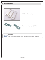
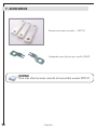
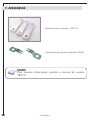
7. ACCESSORIES
UMCT 6 – Connecting bar
Screw mounting adapter (PLMP)
NOTE!
For more information, refer to the SRW 01 user manual.

- Español -
17
Guía de Instalación, Conguración y Operación del SRW 01
UMCT (Unidad de Medición de Corriente/Tensión)
I. INSTRUCCIONES DE SEGURIDAD
Todos los procedimientos de seguridad descritos en el manual del
SRW 01 deben ser seguidos. La no consideración de los procedimientos
recomendados puede levar a la muerte, heridas graves y daños materiales
considerables.
II. INFORMACIONES GENERALES
Este guía orienta la instalación, configuración y operación de la Unidad
de Medición de Corriente/Tensión (UMCT) del Relé Inteligente SRW 01.
III. CONTENIDO DEL EMBALAJE
- Unidad de Medición de Corriente/Tensión del SRW 01;
- Guía de Instalación, configuración y puesta en marcha.
1. INSTALACIÓN
Las orientaciones y sugerencias deben ser seguidas visando el correcto
funcionamiento y la seguridad del personal y de los equipamientos. Los
procedimientos están separados en:
- Instalación mecánica;
- Instalación eléctrica.

- Español -
18
2. INSTALACIÓN MECÁNICA
La Unidad de Medición de Corriente/Tensión (UMCT) puede ser
instalada en cualquier posición.
Las UMCTs 1, 2, 3 y 4 pueden ser montadas directamente en el riel
DIN 35 mm o a través de tornillos M4, utilizando el accesorio adaptador
para fijación por tornillo (PLMP).
Las UMCTs 5 y 6 solamente permiten su montaje a través de tornillos M4.
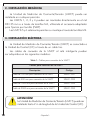
3. INSTALACIÓN ELÉCTRICA
La Unidad de Medición de Corriente/Tensión (UMCT) es conectada a
la Unidad de Control (UC) a través de un cable tira.
Los cables de conexión de la UMCT al relé inteligente pueden
ser adquiridos en los siguientes modelos:
Table 1: Cables para conexión de la UMCT
Cables para conexión de la UMCT
Descripción Código
Cable de 120 mm para conexión de la UMCT SRW01-CB1
Cable de 500 mm para conexión de la UMCT SRW01-CB2
Cable de 1000 mm para conexión de la UMCT SRW01-CB4
Cable de 2000 mm para conexión de la UMCT SRW01-CB3
¡ATENCIÓN!
La Unidad de Medición de Corriente/Tensión (UMCT) puede ser
instalada hasta 2 m de longitud de la Unidad de Control (UC).

- Español -
19
4. PROCEDIMIENTO DE INSTALACIÓN
1 - UMCT
2 - Cable de conexión SRW01-CBx
3 - Fijación en riel DIN 35 mm
4 - Fijación con tornillo utilizando el
accesorio PLMP

- Español -
20
5 (a) - Conexión del cable a la UMCT
5 (b) - Conexión del cable a la UMCT
La otra extremidad del cable deberá ser conectada a la Unidad de
Control (UC), a través del conector localizado en la parte superior, de la
misma forma que es presentado en los procedimientos 5(a) y 5(b).
¡NOTA!
No retire el cable de conexión usando el propio cable, bajo
riesgo de dañarlo.
¡NOTA!
Las UMCTs 5 y 6 solamente permiten su montaje a través
de tornillos M4.
A página está carregando...
A página está carregando...
A página está carregando...
A página está carregando...
A página está carregando...
A página está carregando...
A página está carregando...
A página está carregando...
A página está carregando...
A página está carregando...
A página está carregando...
A página está carregando...
A página está carregando...
A página está carregando...
A página está carregando...
A página está carregando...
A página está carregando...
A página está carregando...
A página está carregando...
A página está carregando...
A página está carregando...
A página está carregando...
-
 1
1
-
 2
2
-
 3
3
-
 4
4
-
 5
5
-
 6
6
-
 7
7
-
 8
8
-
 9
9
-
 10
10
-
 11
11
-
 12
12
-
 13
13
-
 14
14
-
 15
15
-
 16
16
-
 17
17
-
 18
18
-
 19
19
-
 20
20
-
 21
21
-
 22
22
-
 23
23
-
 24
24
-
 25
25
-
 26
26
-
 27
27
-
 28
28
-
 29
29
-
 30
30
-
 31
31
-
 32
32
-
 33
33
-
 34
34
-
 35
35
-
 36
36
-
 37
37
-
 38
38
-
 39
39
-
 40
40
-
 41
41
-
 42
42


WEG SRW 01-UMCT Guia de usuario
- Tipo
- Guia de usuario
- Este manual também é adequado para
em outras línguas
- español: WEG SRW 01-UMCT Guía del usuario
Artigos relacionados
-
WEG SRW01 Guia de usuario
-
WEG CFW-08 Manual do usuário
-
-
-
-
-
-
-
-
WEG CFW100 Manual do usuário