Dell Latitude 3340 Manual do proprietário
- Tipo
- Manual do proprietário

Page 1
Statement of Volatility – Dell Latitude 3340
CAUTION: A CAUTION indicates either potential damage to hardware or loss of data and tells you how to avoid the problem.
The Dell Latitude 3340 contains both “volatile” and “non-volatile” (NV) components. Volatile components
lose their data immediately upon removal of power from the component. Non-volatile components
continue to retain their data even after the power has been removed from the component. The following
NV components are present on the Dell Latitude 3340 motherboard:
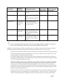
Table 1. List of Non-Volatile Components on System Board
Description
Reference
Designator
Volatility Description
User
Accessible for
external data
Remedial Action
(action necessary
to lose data)
Embedded Flash in
embedded
controller
MEC5075
U2401 292K byte of embedded
Flash memory for keyboard
controller BIOS code, asset
tag and BIOS passwords
No NA
Panel EEDID
EEPROM
Part of panel
assembly
Non Volatile memory, 128
bytes.
Stores panel manufacturing
information, display
configuration data
No NA
System BIOS U2501 Non Volatile memory,
64Mbit (8MB), System BIOS
and Video BIOS for basic
boot operation, PSA (on
board diags), PXE diags.
No NA
System Memory –
DDR3L memory
Two Sodimm
connectors:
DM1, DM2
Volatile memory in OFF state
(see state definitions later in
text)
One or both modules will be
populated. System memory
size will depend on Sodimm
modules and will be
between 2GB and 8GB
inclusive
Yes Power off system
System memory
SPD EEPROM
On memory
SoDIMM(s) –
one or two
present
Non-Volatile memory 2Kbit
(256 bytes). One device
present on each SoDIMM.
Stores memory
manufacturer data and
timing information for
No NA

Page 2
Description
Reference
Designator
Volatility Description
User
Accessible for
external data
Remedial Action
(action necessary
to lose data)
correct operation of system
memory.
RTC CMOS CPU1 Non Volatile memory 256
bytes
Stores CMOS information in
PCH
No NA
Video memory –
frame buffer
UMA
architecture-
uses system
DDR3L.
Volatile memory in off state.
UMA uses main system
memory size allocated out
of main memory.
No Power off
Hard drive(s) User
replaceable
Non Volatile magnetic
media, various sizes in GB.
May also be SSD (solid state
flash drive)
Yes Low level format
mSATA User
replaceable
mSATA module would share
with Hard drive (or SSD)
location with an interposer
board.
Yes Low level format
CAUTION: All other components on the system board lose data if power is removed from the system. Primary power loss (unplugging
the power cord and removing the battery) destroys all user data on the memory (DDR3, 1067 MHz). Secondary power loss (removing
the on-board coin-cell battery) destroys system data on the system configuration and time-of-day information.
In addition, to clarify memory volatility and data retention in situations where the system is put in different
ACPI power states the following is provided (those ACPI power states are S0, S1, S3, S4 and S5):
S0 state is the working state where the dynamic RAM is maintained and is read/write by the processor.
S1 state is a low wake-up latency sleeping state. In this state, no system context is lost (CPU or chip
set) and hardware maintains all system contexts.
S3 is called “suspend to RAM” state or stand-by mode. In this state the dynamic RAM is maintained.
Dell systems will be able to go to S3 if the OS and the peripherals used in the system supports S3 state.
Linux, Win 2K and Win XP support S3 state.
S4 is called “suspend to disk” state or “hibernate” mode. There is no power. In this state, the dynamic
RAM is not maintained. If the system has been commanded to enter S4, the OS will write the system
context to a non-volatile storage file and leave appropriate context markers. When the system is
coming back to the working state, a restore file from the non-volatile storage can occur. The restore
file has to be valid. Dell systems will be able to go to S4 if the OS and the peripherals support S4 state.
Win 2K and Win XP support S4 state.
S5 is the “soft” off state. There is no power. The OS does not save any context to wake up the system.
No data will remain in any component on the system board, i.e. cache or memory. The system will
require a complete boot when awakened. Since S5 is the shut off state, coming out of S5 requires

Page 3
power on which clears all registers.
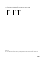
The following table shows all the states supported by Dell Latitude™ 3340:
Model
Number
S0 S1 S3 S4 S5
Dell
Latitude™
3340
X X X X X
______________
Copyright © 2014 Dell Inc. All rights reserved. This product is protected by U.S. and international copyright and intellectual
property laws.
Dell
™ and the Dell logo are trademarks of Dell Inc. in the United States and/or other jurisdictions. All other marks and names
mentioned herein may be trademarks of their respective companies.
-
 1
1
-
 2
2
-
 3
3


Dell Latitude 3340 Manual do proprietário
- Tipo
- Manual do proprietário
em outras línguas
- English: Dell Latitude 3340 Owner's manual